Volume 2, Issue 10, October 2013
Page 17
Abstract
Main objectives of this paper is to review the work already done related to self phase modulation reductiopn for WDM Transmission using EDFA. For 10-Gb/s transmission over nondispersion shifted fiber, the combined use of self-phase modulation (SPM) and joint optimization of the bias and modulation voltages to increase the dispersion limited transmission distance is considered for multiple quantum well Mach–Zehnder modulators. The effects of nonlinearity on sub-500 fs pulse transmission over dispersion compensated fiber links using dispersion compensating fiber technique are investigated numerically and experimentally.
Keywords: EDFA, SPM, CDMA, TDMA, Dispersion compensation, femtosecond pulses, fiber optics, self-phase modulation
1. INTRODUCTION
In this paper we will review the work done by the different research fellows and professors related to SPM reduction for WDM transmission using EDFA.
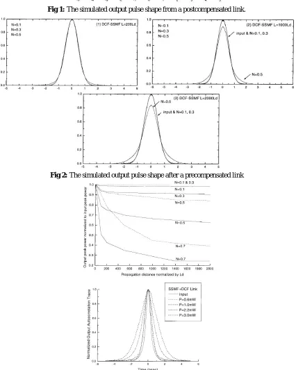
Shuai Shen, Cheng-Chun Chang, Harshad P. Sardesai, Vikrant Binjrajka1 in this paper the effects of nonlinearity on sub-500 fs pulse transmission over dispersion compensated fiber links using dispersion compensating fiber technique are investigated numerically and experimentally. The pulse broadening and recompression ratio of the 2.5-km transmission link is over 300. The postcompensated and precompensated links are compared when the input pulse energy ranges from 15 to 150 pJ. At high powers, self-phase modulation (SPM) degrades the pulse recompression process and provides an upper bound on the transmitted pulse energy. The SPM effect is stronger in the postcompensated link than in the precompensated link. A dramatic spectral narrowing effect was observed in the postcompensated link. Pulse energies up to tens of pJ, consistent with high quality communication, should be possible for a sub-500 fs pulse in such dispersion compensated links.
Volume 2, Issue 10, October 2013
Page 18
Fig 2: The simulated output pulse shape after a precompensated link
Fig. 3. Measured intensity autocorrelation traces of input and output pulses after a 2.5-km postcompensated link (normalized to unit amplitude). The input average power P = 0:6; 1:0; 2:2, and 3:0 mW with pulse repetition rate of 33
Volume 2, Issue 10, October 2013
Page 19
Fig. 4. Measured and simulation results of input and output pulse spectrum FWHM due to the SPM effect in a 2.5-km dispersion compensated link (solid line and dashed line: simulation results; circle, triangle, square: experiment data).
The interaction between the fiber dispersion and the SPM effect was shown to be a major factor that limits the amount of energy allowed to be launched into the dispersion compensated transmission link for fs pulses in our numerical and experimental study. This power limit will eventually provide an upper bound on the length of the transmission link due to the increasing loss for the longer link. Effects due to SPM are stronger for the postcompensated link. Nonetheless, our results indicate that transmission of sub-500 fs pulses in a dispersioncompensated fiber link should be possible at energy up to tens of pJ, which is consistent with high-quality com unication. For the better pulse transmission, the precompensated scheme should be employed. We noted our result is overconservative for the CDMA pulse transmission where the spectrally coded pulse has much smaller peak power than the isolated unshaped input pulse. It is overly optimistic for the very high rate TDM pulse transmission when the pulse-to-pulse interactions can increase the nonlinearities compared to those that with a single isolated input pulse. Nevertheless, our study provides insight into the interaction between SPM and fiber dispersion in a dispersion compensated link for fs pulses. To our knowledge, this is the first numerical and experimental study of self-phase modulation in dispersion compensated fiber links for fs pulse transmission.
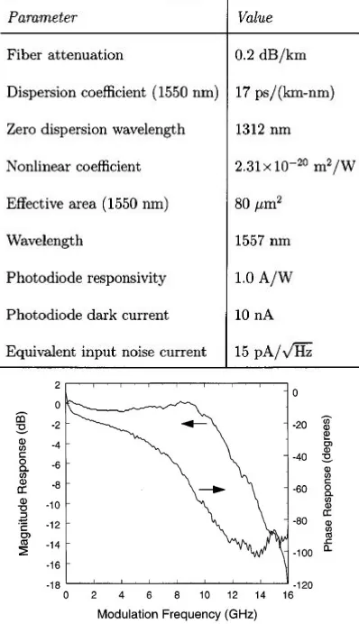
J. C. Cartledge 2 For 10-Gb/s transmission over nondispersion shifted fiber, the combined use of self-phase modulation (SPM) and joint optimization of the bias and modulation voltages to increase the dispersion limited transmission distance is considered for multiple quantum well Mach–Zehnder modulators. For the dual drive (push-pull) modulation format, the dependence of the receiver sensitivity on fiber length and average transmitted optical power is determined for both conventional and phase-shift modulators with either symmetric or asymmetric Y-branch waveguides. When SPM is negligible and the optical extinction ratio is maximized, the modulator design must be considered carefully in order to increase the transmission distance. By combining SPM and optimum modulation conditions, the dependence of the system performance on the modulator design is reduced substantially. For an average transmitted optical power of 12.5 dBm, the receiver sensitivity for transmission over 140 km of fiber varies by only 0.3 dB for the different modulator designs. This compares with a variation of 3.1 dB for maximum extinction ratio modulation
Fig. 5. Dependence of the absorption and phase of the optical signal on applied voltage for each arm of a π phase-shift modulator with a splitting ratio of 1.3
Volume 2, Issue 10, October 2013
Page 20
Table 1: PARAMETER VALUES FOR 10 Gb/s SYSTEM PERFORMANCE EVALUATION
Fig8: Frequency response for the MQW Mach–Zehnder modulator
Volume 2, Issue 10, October 2013
Page 21
Fig. 10. Dependence of the receiver sensitivity on fiber length for a conventional modulator with a splitting ratio of 1. Results are presented for maximum extinction ratio modulation (dashed line) and optimized modulation (solid line) with
average transmitted optical powers of 7.5, 10, and 12.5 dBm
Fig. 11. Dependence of the optimum bias and modulation voltages on fiber length for a conventional modulator with a splitting ratio of 1. Results are presented for average transmitted optical powers of 7.5, 10, and 12.5 dBm. The optimum
bias voltage for arm 1 is given by Vb1=-4-Vb2
Fig. 12. Dependence of the receiver sensitivity on fiber length for a conventional modulator with a splitting ratio of 1 and an optically preamplified receiver. Results are presented for maximum extinction ratio modulation (dashed line) and
optimized modulation (solid line) with average transmitted optical powers of 7.5, 10, and 12.5 dBm.
Fig. 13. Dependence of the receiver sensitivity on fiber length for a conventional modulator with a splitting ratio of 0.75. Results are presented for maximum extinction ratio modulation (dashed line) and optimized modulation (solid line) with
Volume 2, Issue 10, October 2013
Page 22
Fig. 14. Dependence of the optimum bias and modulation voltages on fiber length for a conventional modulator with a splitting ratio of 0.75. Results are presented for average transmitted optical powers of 7.5, 10, and 12.5 dBm. The
optimum bias voltage for arm 1 is given by Vb1=-4-Vb2
Fig. 15. Dependence of the receiver sensitivity on fiber length for aπ phase-shift modulator with a splitting ratio of 1. Results are presented for maximum extinction ratio modulation (dashed line) and optimized modulation (solid line) with
average transmitted optical powers of 7.5, 10, and 12.5 dBm.
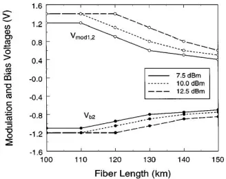
Fig. 16. Dependence of the optimum bias and modulation voltages on fiber length for a π phase-shift modulator with a splitting ratio of 1. Results are presented for average transmitted optical powers of 7.5, 10, and 12.5 dBm. The optimum
bias voltage for arm 1 is given by Vb1=-4-Vb2
Fig 17. Dependence of the receiver sensitivity on fiber length for a π phase-shift modulator with a splitting ratio of 1.3. Results are presented for maximum extinction ratio modulation (dashed line) and optimized modulation (solid line) with
Volume 2, Issue 10, October 2013
Page 23
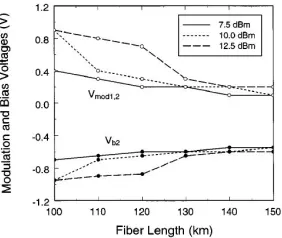
Fig. 18. Dependence of the optimum bias and modulation voltages on fiber length for a π phase-shift modulator with a splitting ratio of 1.3. Results are presented for average transmitted optical powers of 7.5, 10, and 12.5 dBm. The optimum
bias voltage for arm 1 is given by Vb1=-4-Vb2
Fig. 19. Dependence of the receiver sensitivity and optimum bias voltage V on modulation voltage for a π phase-shift modulator with a Y-branch plitting ratio of 1.3. The fiber length is 140 km. The optimum bias voltage for arm 1 is given
by Vb1=-4-Vb2
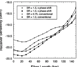
Fig. 20. Summary of results for the dependence of the receiver sensitivity on fiber length for the four modulators. Results are presented for optimized modulation and an average transmitted optical power of 12.5 dBm.
The combined use of SPM and optimization of the bias and modulation voltages to increase the dispersion limited transmission distance of 10 Gb/s systems using nondispersion shifted optical fiber has been studied. Conventional and π
Volume 2, Issue 10, October 2013
Page 24
Fiber Commun., San Jose, CA, 1993, paper PD-27.
[5] J. C. Cartledge, C. Rolland, S. Lemerle, and A. Solheim, “Theoretical performance of 10 Gb/s lightwave systems using a III–V semiconductor Mach–Zehnder modulator,” IEEE Photon. Technol. Lett., vol. 6, pp. 282–284, 1994. [6] D. M. Adams, C. Rolland, N. Puetz, R. S. Moore, F. R. Shepherd, H. B. Kim, and S. Bradshaw, “Mach–Zehnder
modulator integrated with a gain-coupled DFB laser for 10 Gbit/s, 100 km NDSF transmission at 1.55 _m,” Electron. Lett., vol. 32, pp. 485–486, 1996.
[7] H. Sano, T. Ido, S. Tanaka, and H. Inoue, “10 Gb/s, 80 km normal fiber transmission by using multiple-quantum well Mach–Zehnder modulator,” in Optoelectron. Commun. Conf., Chiba, Japan, 1996, paper 17D2-4.
[8] P. Delansay, D. Penninckx, S. Artigaud, J.-G. Provost, J.-P. Hébert, E. Boucherez, J. Y. Emery, C. Fortin, and O. Le Gouezigou, “10 Gbit/s transmission over 90-127 km in the wavelength range 1530–1560 nm using an InP-based Mach–Zehnder modulator,” Electron. Lett., vol. 32, pp. 1820–1821, 1996.
[9] J. Yu, C. Rolland, A. Somani, S. Bradshaw, and D. Yevick, “Phase-engineered III–V MQW Mach–Zehnder modulators,” IEEE Photon. Technol. Lett., vol. 8, pp. 1018–1020, 1996.
[10]D. Penninckx, P. Delansay, E. Boucherez, C. Fortin, and O. Le Gouezigou, “InP/GaInAsP _-phase shifted Mach– Zehnder modulator for wavelength independent (1530–1560 nm) propagation performance at 10 Gbit/s over standard dispersive fiber,” Electron. Lett., vol. 33, pp. 697–698, 1997.
[11]D. Penninckx and P. Delansay, “Comparison of the propagation performance over standard dispersive fiber between InP-based _-phase-shifted and symmetrical Mach–Zehnder modulators,” IEEE Photon. Technol. Lett., vol. 9, pp. 1250–1252, 1997.
[12]C. Lawetz, J. C. Cartledge, C. Rolland, and J. Yu, “Modulation characteristics of semiconductor Mach–Zehnder optical modulators,” IEEE J. Lightwave Technol., vol. 15, pp. 697–703, 1997.
[13]P. Delansay, S. Gauchard, H. Helmers, D. Penninckx, S. Gurib, and F. Brillouet, “2.5 Gbit/s transmission over 1086 km of standard single-mode fiber using an integrated laser Mach–Zehnder modulator,” in Proc. Conf. Optical Fiber Commun., San Jose, CA, 1998, paper TuI7.
[14]C. Rolland, “InGaAsP-based Mach–Zehnder modulators for high-speed transmission systems,” in Proc. Conf. Optical Fiber Commun., San Jose, CA, 1998, paper ThH1.