Review of Realization of Three Phase Two Stage Grid System by
Using LLC Resonant Converter
Bhooshan Dileep Darkonde, Prof. Prabhodh kumar Khampariya
SSSIST, Sehore, State Madhya Pradesh, India
Abstract— Module integrated converters (MICs)
in single phase have witnessed recent market
success because of unique features such as
improved energy harvest, improved efficiency of
the system, lower installation costs, plug-and
play operation, and enhanced flexibility and
modularity. A niche market has been grown by
the MIC sector to mainstream, especially in the
United States. Assuming further expansion of the
MIC market, this paper presents the micro
inverter concept incorporated in large size
photovoltaic (PV) installations such as
megawatts (MW)-class solar farms where a
three-phase ac connection is employed. A
high-efficiency three-phase MIC with two-stage zero
voltage switching (ZVS) operation for the
grid-tied PV system is proposed which will reduce
cost per watt, improve re-liability, and increase
scalability of MW-class solar farms through the
development of new solar farm system
architectures. The first stage mainly considered
for a high efficiency full-bridge LLC resonant
dc–dc converter which interfaces to the PV panel
and produces a dc link voltage. A center point’s
iteration algorithm developed specifically for
LLC resonant topologies is used to track the
maximum power point by the PV panel. The
second stage is comprised of a three-phase dc–ac
inverter circuit which employs a simple
soft-switching scheme without adding auxiliary
components.
Keywords- Center points iteration (CPI),
maximum power point tracking (MPPT), module
integrated converter (MIC), three phase two
stage converter.
I. Introduction
With ever degenerate natural resources and
increasing demands for power, the need to seek out
viable alter-native sources of renewable energy is
not just critical urgent. Due to the fact that solar
energy offers extraordinary merits including
environmentally neutral, unlimited availability and
low cost capable of competing with conventional
sources with technology advances and mass
production in the coming few years. Over of 25%
growth on an average over the last 10 years has
been seen by the photovoltaic (PV) industry Other
than the PV panel itself [1], the inverter is the most
critical device in a PV system both for off-grid or
grid-connection applications because the property of
the inverter uses to converts dc supply to ac supply
and ac supply is converted in dc supply is called as
rectifier, this is called as converter. The basic
concept of the converter is that to get the required
supply. Now-a-days, the PV system architectures
can be categorized into three basic classes with
respect to the types of grid-tied inverter: i) central
inverter, ii) string or multi string inverter, iii)
module integrated converter (MIC) (also called
micro inverter) [2] [3]. Although the central inverter
can be operated at high efficiency with only one
drawbacks: (1) Each PV module may not operate at
its maximum power point which results in less
energy utilized. (2) Additional losses are
take-placed by string diodes and junction box; and (3)
Single point of failure and Mismatch of each string
or PV panel affects the PV array efficiency greatly.
The string inverter is a modified version of the
central inverter. It partially overcomes the issues
arising in central inverters; however, it still suffers
some of the drawbacks of the central inverter. In an
effort to maximize the power from each PV panel, a
new approach was recently proposed which can be
applied to either central or string inverter
architectures. A power maximize is attached to each
PV panel to utilized maximum power tracking.
Although the architecture maximizes power from
each PV panel at the cost of additional dc/dc
module, it still suffers from such drawbacks like
high-voltage hazard, single-point failure, and
difficulty in maintenance. The MIC typically used
in distributed PV systems is a small grid-tie inverter
of 150–400 W that converts the output of a single
PV panel to ac. The MIC ac outputs are connected
in parallel and routed to a common ac coupling
point. No series or parallel dc connections are made
leaving all dc wiring at a relatively low voltage
level of a single panel module. The MIC can be
further integrated into PV modules to realize a true
plug-and-play solar ac PV generation system. Thus,
ac PV modules with integrated MIC have
significant advantages over traditional PV systems
since they allow maximum peak power tracking on
each solar panel to maximize energy utilizing, and
offer distributed and redundant system architecture.
In addition, MIC and ac PV systems greatly
simplify system design, eliminate safety hazards,
and reduce installation costs .With these
advantages; the trend for future PV system has been
became by the ac module for development.
Although MIC and ac PV modules have witnessed
recent market success, MIC still has many technical
challenges remaining such as high efficiency, high
reliability at module level, low-cost and high-level
control issues. To date, research of the MIC has
mainly focused on isolated topologies for the
following two reasons: 1) from reported literature,
most topologies with a few exceptions cannot meet
the dual grounding requirement without transformer
isolation according to the UL1741 standard; and 2)
using transformer is the best way to boost the low
input voltage to high output voltage for ac grid with
high efficiency. Since line transformers are bulky
and costly, this architecture is not practical for MIC.
This paper mainly focuses on the architecture
employing a high-frequency transformer. The MIC
with its high-frequency transformer can be grouped
into three architectures based on the dc-link
configurations: dc-link, pseudo-dc-link, and
high-frequency ac. Usually the MIC just pumps the
power from PV to ac grid with unidirectional power
flow. However, with the presence of the power
decoupling capacitor, MIC can support the ac grid
not only as an ac power source, but as a VAR and
possibly a harmonics compensator as well. For the
latter two cases, bidirectional power flow is needed
between ac grid and the power decoupling capacitor
requiring MIC with bidirectional power flow
capability. For applications with power levels under
several kilowatts, generally the single-phase
connections are used.
II. Literature Survey
Resonant converters have been cramped in the last
some decades of years to niche applications such as
systems while much effort was spent in research by
industries and universities because of its attractive
features: smooth waveforms, high efficiency and
high power density. In recent times the LLC
resonant Converter in particular in its half-bridge
implementation, has been widely and successfully
applied to flat panel TV, 80+ ATX and small form
factor PC, where the requirements on efficiency,
power density and EMC compliance of their
switching mode power supplies (SMPS‟s) are
getting more and more rigid. However future SMPS
requirements will have to face one of the few
remaining disadvantages of LLC resonant converter
topology that is related to the output filter capacitors
volume that represents the major limit for such
applications. The injection of rectified sine wave
currents into the output filter capacitor can be
adequately mitigated by the parallel use of multiple
modules such as in interleaved buck solutions for
voltage regulator modules. This topology has been
presented in for two modules operating with 90
degrees phase shift. One of the drawback of this
solution is represented by the inherent current
unbalance caused by resonant component mismatch
that may cause one of the two modules to reduce its
output power down to zero, thus requiring
mandatory workarounds to overcome the problem
Resonant converters are commonly selected for
applications which demand for a high power density
and a high energy efficiency. By featuring
soft-switching, the switching frequency can in general be
chosen much higher than the switching frequency of
a comparable hard-switching converter. As a
consequence, the volume required for the passive
components is drastically reduced, enabling high
power densities and high power conversion
efficiencies. In this paper, a highly efficient battery
charger has been designed, for which is capable of
bidirectional charging light electric vehicles
(LEVs). The charger will be connected to a dc
micro-grid at Vdc = 450V and will feature an
output voltage range from 17V to 56V. For limiting
the duty-cycle and/or frequency variation, and to
provide galvanic separation from the dc-bus, a
transformer is needed for this type of application;
the LLC resonant converter synchronizes
remarkable unidirectional performance. In a
bidirectional LLC prototype was built, but no
optimized modulation schemes were employed and
the converter did not achieve satisfactory power
conversion efficiency. In a Symmetric fourth-order
resonant converter was built based on an LLC
resonant tank, featuring an additional resonant
capacitor. However, the proposed CLLC converter
operates in boost-mode in both directions and is
therefore not very suitable for use as a
voltage-regulating converter. the LLC resonant converter
has been drawn a lot of attention due to its
drawbacks over the conventional series resonant
converter and parallel resonant converter, narrow
frequency variation over wide load and input
variation and Zero Voltage Switching (ZVS) of the
switches for entire load range. An analysis and
reviews practical design considerations are
presented in this paper for the LLC-type resonant
converter. It includes designing the transformer and
selecting the components. The step-by-step design
procedure explained with a design example will
help engineers design the LLC resonant converter
easily. The effect of resonant component mismatch
will also be explored and a suitable star connection
solution will be investigated to overcome current
derating limits by means of intrinsic balancing.
the paper as validation of assertions and proposals
[4]. The Basic requirements of battery chargers with
switching regulators are small sized and high
efficiency. High switching frequency is necessary to
achieve a small size. However, the switching loss
will increase as the switching frequency is
increased. This condition, in turn, decreases the
efficiency. To solve this problem, some kinds of
soft-switching techniques need to be used to operate
under high switching frequency. One simple
solution to a soft-switching converter is loaded
resonant converters. By adopting these topologies,
either voltage or current is zero during switching
transition, which largely reduce the switching loss
and also increase the reliability for the battery
charger. It eliminates both lowland high frequency
current ripples on the battery, thus maximizing
battery life without penalizing the volume of the
charger [5]. The isolated unidirectional LLC
resonant converter is known for its outstanding
efficiency and high power density. Little
information has however been published about the
possibility of transferring power in the reverse
direction. This paper presents modulation schemes
for making the LLC converter bidirectional. High
efficiencies are predicted for both directions of
power flow, though, as the behavior of the resonant
tank is substantially different in the reverse
direction, some of the inherent benefits of the
conventional LLC converter are lost [6]. In this
paper a topology for multi-phase interleaved LLC
resonant converter is presented. The proposed
solution, based on three LLC modules with
transformer primary windings star connection
allows to drastically reduce the output current ripple
and consequently to minimize the output filter
capacitor size. Differently from other multi-phase
solutions, that are greatly susceptible to resonant
component mismatch and consequently can be
affected by a considerable current imbalance among
modules, the proposed topology exhibits an inherent
balancing capability. Small-signal analysis is
presented and the possibility to turn-off one or two
modules (phase shedding) at reduced output current
levels is discussed, highlighting the trade-off
between converter efficiency and output capacitor
current ripple reduction. Measurements on a
prototype will be included in the paper as validation
of assertions and proposals [7].
III. Theory of Architecture Two-Stage
Three-Phase Grid-Tie Inverter System
In order to provide galvanic isolation, various
isolated converters for high step up applications
have been proposed. In general, the topologies with
galvanic isolation suitable for this application can
be categorized into two groups: single-switch
topologies and multi switch topologies. Recently,
the LLC resonant topology has become attractive
due to its desirable characteristics such as high
efficiency and natural zero voltage switching
(ZVS)/zero current switching (ZCS) commutation.
Therefore, a full-bridge LLC resonant converter is
employed in the first stage to achieve high
efficiency and track the maximum power point of
each PV panel. For the three-phase dc/ac converter
in the second stage, a variety of active
soft-switching topologies have been proposed in last
three decades. Most of them can be divided into
three groups: auxiliary resonant commutated pole
(ARCP) group, resonant dc-link inverter (RDCLI)
group, and resonant ac-link converter (RACLC),
The ARCP can be applied broadly for the
it requires a large number of auxiliary components.
Compared to the ARCP, the RDCLI has the
advantages of fewer auxiliary switches and a
simpler circuit. Several soft-switching topologies in
were proposed to achieve the minimum number of
extra components. However, the driving signals of
the auxiliary switches are very sensitive to the noise
from the main circuit. Since the RACLC can
achieve voltage boosting and electrical isolation at
the same time, it is highly preferred for renewable
energy power generation. Unfortunately, the control
circuit for the RACLC is complex and bidirectional
switches are required. In fact, auxiliary components
are unavoidable for all of the soft switching
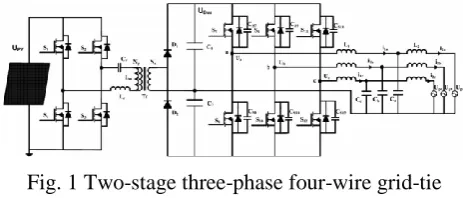
topologies mentioned earlier. The proposed
soft-switching technique shown in Fig.1 simplifies the
inverter topology and reduces the cost since it does
not require any auxiliary components.
Fig. 1 Two-stage three-phase four-wire grid-tie
inverter system.
The body capacitors of the main MOSFETs and the
output inductor L1 are combined to form a resonant
circuit. The inductor current is intentionally
bidirectional within a switching cycle to generate
ZVS conditions during commutation. Meanwhile
the average inductor current is controlled to produce
a sinusoidal current in L1. The proposed
soft-switching technique is suitable for MIC applications
where the switching losses are usually dominant.
Based on the above, Fig. 1 shows the proposed
high-efficiency MIC architecture with both-stage
zero-voltage switching consisting of a full-bridge
LLC resonant dc–dc step up converter and three
phase four-wire soft-switching dc–ac converter. The
detail operating modes in the three-phase four wire
dc/ac converter will be presented in the following
sections.
3.1 Full Bridge LLC Resonant Converter
Secondary batteries are widely used in the
application of residential, industrial, and
commercial energy storage systems to store
electricity and supply the load for various types of
electronic equipment [1]–[7]. If the dc source is
directly connected to the secondary battery, the
output voltage of the dc source is fixed to the
voltage of the secondary battery; therefore, the
system cannot always operate at each optimum
operating point. Therefore, it is necessary to install a
dc–dc interface between the dc source and the
secondary battery to make the energy storage
system always operates at the optimum operating
points. This dc–dc interface is also called the battery
charger. The traditional battery charger, which
extracts power from an ac-line source, requires a
thyristor ac/dc converter rectifier with an equivalent
series resistance to control the power flow to charge
the battery system. Such a charging circuit
necessarily draws a high-ripple charging current.
Accordingly, as the concern about the quality of a
charger grows, a charging circuit for reducing the
ripple and extending the battery life becomes more
important in designing the battery storage systems.
Several charging circuits have been proposed to
overcome the disadvantages of the traditional
battery charger. Unlike linear regulators, switching
regulators use active power switches to operate in
either the saturation region or the cutoff region.
Because either region will lead to low switching
convert a dc voltage to a different level with greater
efficiency, as well as with low cost, relatively small
size, and light weight between the two columns.
The life and capacity of the secondary batteries
depend on several factors e.g., charge mode,
maintenance, temperature and age. Among these
factors, the charge mode has a great impact on
battery life and capacity. The secondary batteries
should be charged with current and voltage levels
with low ripple. Therefore, a high-performance
battery charger is necessary in a battery energy
storage system. In addition, the basic requirements
of battery chargers with switching regulators are
small sized and high efficiency. High switching
frequency is necessary to achieve a small size.
However, the switching loss will increase as the
switching frequency is increased. This condition, in
turn, decreases the efficiency of the battery
chargers. To solve this problem, some kinds of
soft-switching techniques need to be used to operate
switching frequency. One simple solution to a soft-
switching converter is loaded under high resonant
converters. By adopting these topologies, either
voltage or current is zero during switching
transition, which largely reduce the switching loss
and also increase the reliability for the battery
chargers. To minimize the power losses, it is
essential not to waste energy in the conversion
process. In relation to the power electronics and
associated control schemes, the main requirement is
to guarantee that the charging system is efficient.
Therefore, topologies with high frequencies and
soft-switching technique are used to reduce the
charging current ripple and extend battery life.
Among these existing soft-switching converters,
Resonant converters are the most popular ones
because of their simplicity of circuit configuration,
low switching losses, and high flexibility for
charging current regulation. Resonant converters
can be classified, depending on the manner by
which energy is extracted from the resonant tank,
into the following three types: 1) series resonant
converters; 2) parallel resonant converters; and 3)
series–parallel converters. The series resonant
converter is inherently short circuit and protected by
the impedance resonant tank. However, the
drawback of the series resonant converter is that the
charging voltage cannot be regulated at any load
and light-load conditions. The disadvantage of the
parallel converter is that the current in the resonant
components is relatively independent of the load.
The conduction losses are fixed, and the efficiency
of the converter is relatively poor for light loads. On
the other hand, the series–parallel converter
combines the advantages of the series and parallel
converters. The output is controllable for no load or
light load, and the light load efficiency is relatively
high. Accordingly, a series–parallel dc–dc converter
is installed between the ac input source and the
storage batteries to control the operating points of
the dc source.
3.2 Operation Mode of the Proposed ZVS Three
Phase Four-Wire Dc/Ac Converter
Because many articles about LLC resonant
converters have been published over the last decade,
this paper does not discuss it in great detail. The
operating modes of the proposed ZVS three-phase
four-wire dc/ac converter are presented in this
section. As shown in Fig. 3.1, the three phases of
the dc/ac second stage are symmetrical around the
neutral point; therefore, the analysis can be
performed on a single phase as shown in Fig. 3and
Interval 1 [t0 − t1]: Prior to t0, S7 is off and S8 is
still turned ON. Assume that the current direction
through L1, as shown in Fig. 3, is already from right
to left at t0. Then S8 is turned OFF and the voltage
across the parasitic capacitor CS8 of low side
MOSFET S8 starts increasing due to the inductor
current. As CS8 charges the voltage across S7
decreases. This interval ends once the voltage across
S7 reaches zero. Interval 2 [t1 − t2]: The body diode
of S7 will be conducting at t1 and S7 can be turned
ON with ZVS. The current flow decays linearly
from right to left due to the fact that U bus/2 minus
the voltage across L1.
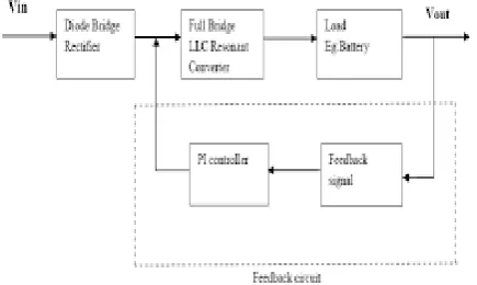
Fig. 2 Block Diagram of Full Bridge LLC Resonant
Converter for Battery Charging Application
This mode ends when the inductor current decays to
zero. Interval 3 [t2 − t3]: S7 is conducting and the
current direction through L1 is now changed from
left to right and increasing linearly. This is the
power delivery interval. Interval 4 [t3 − t4]: At t3,
S7 is turned OFF and its parasitic capacitor CS7 is
charged by the inductor current while CS8 is
discharging. Once the voltage across CS8 drops to
zero, the parasitic body diode of MOSFET S8
conducts since the current direction through L1 does
not change. Interval 5 [t4 − t5]: Continuing from the
previous interval 4, the body diode of S8 continues
conducting which creates a ZVS condition when S8
is turned ON. The length of this interval is typically
quite short and ends once S8 is turned ON. Interval
6 [t5 − t6]: S8 is turned ON under ZVS condition at
t5. The current through S8 is gradually decreasing
due to the fact that U bus/2 plus the output voltage
appears across the inductor L1. During this interval
the energy stored in the inductor is transferred to the
load and the current that was flowing in the body
diode of S8 now flows through the MOSFET on
resistance thus reducing conduction losses. Interval
7 [t6 − t0]: The current through S8 continues to
flow and the current direction will change once the
current decays to zero at t6. Once the current
through S8 changes direction from top to bottom as
shown in Fig. 3.3, a ZVS condition is created for S7
.When the current through S8 reaches the negative
threshold current, the cycle repeats.
Fig. 3 Theoretic waveforms & operating intervals of
a single-phase dc/ac converter. Interval 1: [t0 − t1], interval 2: [t1 − t2], interval 3: [t2 − t3], interval4: [t3 − t4], interval 5: [t4 − t5], interval 6: [t5 − t6], and interval 7: [t6 − t0].
3.3 Interleaved Three Phase LLC Resonant
Converter
LLC Resonant converters exhibit large voltage
ripple on output filter capacitor because of the
rectified sine-wave current injected through the
transformer secondary windings. In order to reduce
the capacitor size and/or the steady-state output
voltage ripple, the interleaved approach can be
profitably applied. The benefit of an increasing
current ripple, that is the peak-to-peak ac current
injected into the output filter capacitor. The results
obtained from MATLAB Simulink Simulations
with 400 V input voltage 24 V output voltage and
different output currents. The huge reduction of
total current ripple in the three modules solution can
be appreciated as compared to one and two modules
counterparts, suggesting the possibility. To
drastically reduce the output filter capacitor size the
use of parallel connected LLC Resonant Converters
to supply the same load and share the same output
filter capacitor presents limitations and
disadvantages caused by resonant devices
mismatch. The modules are operated at the same
switching frequency controlled by the voltage
regulation loop, while resonant component
mismatch causes the three phases to exhibit
different voltage conversion ratios. As a
consequence, the load current is no longer equally
supplied by the modules and one of the phases may
totally reduce its output power to zero illustrates the
results of some measurements on the prototype for
different operating conditions. In presence of
resonant device mismatch in order to emphasize the
mismatch the third module resonant capacitor has
been increased by 12 % by adding A 2.7 Nf
capacitor in parallel to the nominal one (22 Nf). It
can be noticed from the data in the left-half of the
table, that the third module delivers zero output
current,
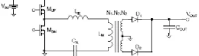
Fig. 4. Scheme of a single module LLC resonant
converter.
In presence of resonant component mismatch this
condition is confirmed by the inspection of the
primary-side currents (400 V Input Voltage, 8 A
output current conditions): The primary-side current
of the third module is indeed interested only by the
magnetizing current. In order to overcome such
limitation, that is unavoidable in mass production, a
three-phase topology is proposed, where the
transformers primary windings are star connected.
This modification allows, by means of the voltage
modulation of star connection point, to greatly
reduce the mean current unbalance caused by
component mismatch. From data shown in the
right-half of, the intrinsic balancing capability of this
topology is pointed out compared to the simple
parallel connection. Moreover, confirm the great
balancing ability of the star connection topology
compared to a simple parallel interleaved
connection.
IV. CAPACITANCE CALCULATION OF
DC-LINK CAPACITOR AND INPUT
CAPACITOR
The dc/dc stage and dc/ac stage are decoupled due
to the action of the dc-link capacitor, simplifying
controller design for both stages. Because of the
three-phase dc/ac converter in the second stage, the
value of the dc-link capacitor can be smaller for a
given MIC power rating. Thus, the reliability of
whole system will be significantly improved if the
electrolytic capacitors are replaced by film
capacitors. Although the capacitance value.
4.1 Advantages of Full Bridge LLC
Using Proposed Converter (Full Bridge LLC), we
can expect Better Controllability than Half Bridge
for wide voltage range. By adopting soft switching
switching transition, which largely reduce the
switching loss and also increase the reliability for
the battery charger. It eliminates both low- and
high-frequency current ripple on the battery,
without using bulky filter capacitor, thus
maximizing battery life without penalizing the
volume of the charger. By use of closed loop control
operation provides more accuracy and stability
under the presence of nonlinearities. Resonant
converter topologies can be used to increase circuit
switching speeds, improved power factor and
reduced switching losses.
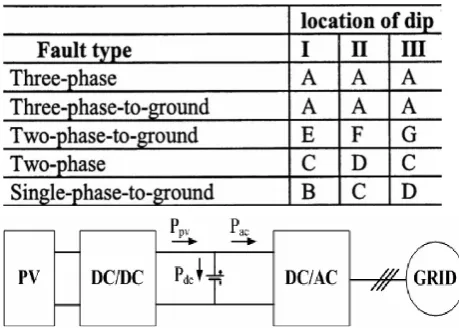
Table I: - three-phase unbalanced dips due to
different fault types and transformer connections
Fig. 5 Simplified block diagram of two-stage MIC
V. CONCLUSION
The closed loop control system of full bridge LLC
Resonant Converter has been examined with help of
MATLAB/SIMULINK. By using soft switching
technique, both low- and high-frequency current
ripple are destructed on the battery, thus
maximizing battery life without penalizing the
volume of the charger, and also reduce the
switching loss. Stability is maintained by use of
closed loop control operation, and provides more
accuracy under the presence of non-linearity‟s .The
High efficiency achieved with a constant output
voltage The proposed topology is made by three
half-bridge LLC converters with transformer
primary windings star connection. This solution
allows to drastically reducing the output current
ripple compared to a single module, and exhibits an
intrinsic balancing capability that is not common to
other resonant interleaved solutions. Small-signal
analysis of the proposed converter has been
performed and a suitable digital control
implemented. The possibility of turning off one or
two phases depending on the overall output current
level, is investigated, and the tradeoff between
converter efficiency and output capacitor current
ripple is discussed. The ZVS operating mode of the
three-phase four-wire dc/ac converter is illustrated.
Average modeling and hybrid control in the dc–ac
stage are also discussed.
REFERENCES
[1]. European Photovoltaic Industry Association,
Global market outlook for photovoltaic until
2016.
[2]. S. B. Kjaer, J. K. Pedersen, and F. Blaabjerg,
“A review of single-phase grid-connected inverters for photovoltaic modules,” IEEE
Trans. Ind. Appl., vol. 41, no. 5, pp. 1292–
1306, Sep./Oct. 2005.
[3]. Y. Xue, L. Chang, S. B. Kjær, J. Bordonau,
and T. Shimizu, “Topologies of single-phase
inverters for small distributed power
generators: An overview,” IEEE Trans. Power
Electron., vol. 19, no. 5, pp. 1305–1314, Sep.
2004.
[4]. Lin Chen, Qian Zhang, Nasser Kutkut,
“Design and Implementation of Three-Phase
Two-Stage Grid- Connected Module Integrated
Converter”, IEEE Trans. On Power
Electronics, Vol. 29, no.8, Aug 2014, PP.
[5]. J.Hepsy Joseph, R. M. Sekar , J. Velmurugan,
“Closed Loop Control of Full Bridge LLC
Resonant Converter for Battery Charging
Application” , „IOSR Journal of Electrical and Electronics Engineering‟ ,ISSN
2278-1676,p-ISSN:2320-3331, vol. 9,Issue 1 Ver. IV (Feb.
2014), PP.91-99.
[6]. A. Hillers, D. Christen and J. Biela, “Design of
a Highly Efficient Bidirectional Isolated LLC
Resonant Converter”, „15th International
Power Electronics and Motion Control
Conference, EPE-PEMC 2012 ECCE Europe,
Novi Sad, Serbia‟
[7]. E. Orietti, P. Mattavelli, G. Spiazzi, C.
Adragna, G. Gattavari, “Analysis of
Multi-Phase Llc Resonant Converters”, Dept. of
Information Engineering – University of
Padova
[8]. E. Roman, R. Alonso, P. Ibanez, S.
Elorduizapatarietxe, and D. Goitia, “Intelligent
PV module for grid-connected PV systems,”
IEEE Trans. Ind. Electron., vol. 53, no. 4, pp.
1066–1073, Jun. 2006.
[9]. http://en.wikipedia.org/wiki/Stock_market
[10]. http://biz.yahoo.com/p/