http://www.sciencepublishinggroup.com/j/rst doi: 10.11648/j.rst.20170306.11
ISSN: 2575-5935 (Print); ISSN: 2575-5943 (Online)
Image Quality and Exposure Control for Over-the-Table
X-ray Systems Using a Flat-panel Detector
Jouji Ohta
1, 2, Koichi Chida
1, 3, *1Department of Radiological Technology, Tohoku University Graduate School of Medicine, Sendai, Japan 2
Department of Radiological Technology, Chiba University Hospital, Chiba, Japan
3Division of Radiation Disaster Medicine, International Research Institute of Disaster Science, Tohoku University, Sendai, Japan
Email address:
[email protected] (K. Chida)
*Corresponding author
To cite this article:
Jouji Ohta, Koichi Chida. Image Quality and Exposure Control for Over-the-Table X-ray Systems Using a Flat-panel Detector. Radiation Science and Technology. Vol. 3, No. 6, 2017, pp. 54-59. doi: 10.11648/j.rst.20170306.11
Received: August 16, 2017; Accepted: October 19, 2017; Published: November 10, 2017
Abstract:
Quality control (QC) is essential for ensuring that the X-ray images produced by fluoroscopy systems are of sufficient quality to provide adequate diagnostic information consistently with the least possible radiation exposure. However, there are limited data on QC (image quality and radiation exposure) in fluoroscopy systems with over-the-table X-ray tubes. We describe a QC protocol for over-the-table fluoroscopy systems. We checked the image quality of over-the-table system using QC phantoms. In this study, over-the-table X-ray system with a flat-panel detector (FPD) was used. The X-ray outputs (i.e., kVp, mA, pulse width) of over-the-table system were evaluated simultaneously. Some QC data (e.g., radiation output and image quality) were scattered, especially when a smaller QC phantom was used, because AEC errors may occur due to inconsistent measurement geometry. Thus, we recommend the use of a phantom holder and beam-limiting tool with a small QC phantom to maintain the measurement geometry of the phantom and X-ray beam. QC is important for over-the-table fluoroscopy systems, as well as under-the-table systems. We cannot ignore QC in over-the-table systems. Generally, the QC protocol for over-the-table systems should be the same as that for under-the-table systems.Keywords: Flat Panel Detector (FPD), Quality Control (QC), Phantom, Fluoroscopy, Angiography,
Over-the-Table X-ray Tube, Image Quality, X-ray Dose1. Introduction
Quality control (QC) is essential in ensuring that X-ray images produced with fluoroscopy systems are of sufficient quality to provide adequate diagnostic information, consistent with the lowest possible radiation exposure [1-10]. However, limited data on QC are available in terms of image quality and radiation exposure in fluoroscopy systems with over-the-table X-ray tubes. To date, QC studies have focused primarily on under-the-table fluoroscopy systems, such as angiographic X-ray systems [11-17].
Staff members operating over-the-table fluoroscopy systems, which are often used in non-vascular interventional radiology (IR), have suffered injuries, such as cataracts, when performing IR procedures [18-22]. When an over-the-table X-ray tube system is used to obtain an anteroposterior view,
the upper part of the IR staff member’s body receives high doses of scattered radiation [23-24]. Thus, the eyes may receive high doses of radiation, sufficient to cause cataracts. Today, we consider the threshold for radiation-induced cataract development to be lower than was previously estimated [25-27].
The QC for over-the-table fluoroscopy systems was insufficient, as it must check not only image quality but also the X-ray output. Thus, the QC of fluoroscopy systems is important not only for under-the-table systems but also for over-the-table systems. Here, we describe a QC protocol for over-the-table fluoroscopy systems.
2. Materials and Methods
using QC phantoms (JSGI phantom and KC-001 phantom). In this study, over-the-table X-ray system (ZEXRA FPD Version, Toshiba, Japan) with a flat-panel detector (FPD) was used.
2.1. JSGI Phantom
Figure 1 shows a commercial JSGI phantom for checking
image quality [28]. This phantom consists of a copper base (thickness, 2.0 mm), acrylic holes and protrusions (diameters, 3 and 5 mm) of various thicknesses (0.25–3 mm), and a square wave chart for determining visual resolution by line-group tests (line widths, 0.15–0.5 mm; Figure 2). The phantom size is 10 × 10 cm2. This QC phantom can aid in the visual evaluation of spatial and low-contrast resolutions.
Figure 1. Appearance of the JSGI quality control phantom and X-ray image used for evaluating image performance. The phantom size was 10 × 10 cm2. A score
of 5 indicated the highest image quality.
Figure 2. Schematic of the JSGI phantom.
2.2. X-ray Output Check
X-ray output (kV, mA, s) can be checked using the values displayed on the X-ray apparatus. These values were not preset in the unit. The displayed values were obtained using the built-in measurement circuitry of the high-frequency X-ray generators.
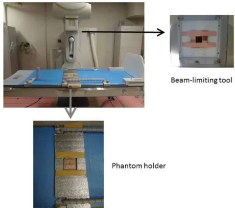
Figure 3. Custom-made JSGI phantom holder and beam-limiting tool used to maintain measurement geometry of the phantom and X-ray beam.
2.3. Phantom Holder and Beam-Limiting Tool
Changes in measurement geometry (beam collimation size and phantom position) can cause errors in automatic exposure control (AEC), such as the system being unable to maintain the correct X-ray output, and/or direct X-ray emission incident to the AEC region of interest (ROI) on the FPD that is not absorbed by the phantom makes the emission appear smaller.
beam-limiting tool to maintain the measurement geometry of the phantom and X-ray beam (Figure 3). The beam-limiting tool consisted of 3-mm-thick copper and was attached to the port of the collimation device; consequently, the radiation field size was 10 × 10 cm at the JSGI phantom. The JSGI phantom holder consisted of a vinyl mat and was attached to the patient support table.
The X-ray exposure factors were as follows: distance between source and FPD, 100 cm; distance between source and phantom surface, approximately 75 cm; and fluoroscopic pulse rate, 15 p/s.
Figure 4. Appearance of the simple quality control phantom (KC-001) used to evaluate flat-panel detector image performance (spatial resolution, low-contrast detectability, and dynamic range).
2.4. Daily Monitoring of an FPD System over 3 Months Using a QC Phantom (KC-001)
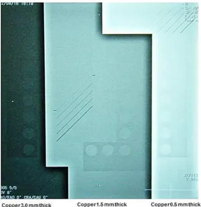
We also performed daily checks of an over-the-table system with an FPD, using an KC-001 phantom instead of the JSGI phantom. The FPD phantom (KC-001) was 20 × 20 cm2 (Figure 4) and consisted of three thicknesses (0.5, 1.5, and 3.0 mm) of copper, an aluminum step wedge (0.1–2.7 mm; hole diameters, 10 mm), and piano wire of various diameters (0.08–0.5 mm; Figure 5) [29]. The QC phantom (KC-001) for FPD systems can be used to evaluate spatial resolution, low-contrast resolution, and the dynamic range of a single X-ray exposure. We also performed daily monitoring of the over-the-table X-ray systems with FPDs (fluoroscopic and radiographic images) using the phantom.
Figure 5. X-ray images of the flat-panel detector phantom (KC-001).
3. Results
3.1. QC Data Using the JSGI Phantom Holder and Beam-Limiting Tool
Figure 6 shows daily X-ray output data (fluoroscopic pulse widths) over 3 months for an over-the-table system under the same conditions, obtained using the JSGI phantom holder and the beam-limiting tool. Pulse widths were not scattered (mean ± SD, 7.73 ± 0.21 ms; SD/mean, 0.03).
Thus, the phantom holder and beam-limiting tool were useful when a smaller phantom (JSGI) was used.
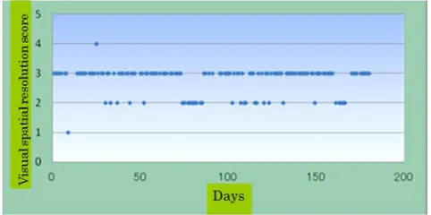
Figure 7 shows daily monitoring data for image quality (spatial resolution) of an over-the-table system obtained using the JSGI phantom under the same conditions. Data for the X-ray system illustrated in Figures 6 and 7 showed no abnormality (no missing data) over the time period.
Figure 7. Example of daily image quality data (spatial resolution, JSGI phantom) for an over-the-table system, obtained under the same conditions (a score of 5 indicates the highest spatial resolution).
3.2. KC-001 Phantom
Figure 8 shows daily X-ray output (pulse width) data for an over-the-table system obtained using the KC-001 phantom under the same conditions. Pulse widths were not scattered (mean ± SD, 6.01 ± 0.08 ms; SD/mean, 0.01), even when the phantom holder and beam-limiting tool were not used. Because the FPD phantom was larger than the JSGI phantom, AEC errors did not occur despite slight changes in measurement geometry because direct X-rays were not incident to the FPD (ROI for AEC).
Figure 8. Example of daily X-ray output data (fluoroscopic pulse widths) for an over-the-table system, obtained using the flat-panel detector under the same conditions (KC-001 phantom).
Figure 9. Example of daily image quality data (spatial resolution) for an over-the-table system, obtained using the flat-panel detector phantom (KC-001) under the same conditions (a score of 10 indicates the highest spatial resolution).
Figure 9 shows daily image quality data (visual spatial resolution scores) for an over-the-table system obtained using the FPD phantom under the same conditions. Using this
phantom, we readily evaluated the performance of the FPD system, including spatial resolution (using the piano wires), low-contrast resolution (using the aluminum step wedge), and dynamic range [using the aluminum step wedge and thin and thick (0.5- and 3.0-mm) pieces of copper].
Figure 10. Example of daily X-ray output data (fluoroscopic tube currents, mA) for an over-the-table system under the same conditions. We found abnormal data (arrow), although the daily measurement parameters (phantom, field size, source to image receptor distance) were apparently consistent. This problem was corrected by the service engineer.
4. Discussion
Examples of abnormal QC data
Figure 10 shows example data for daily checks of fluoroscopic X-ray output (tube currents) of an over-the-table fluoroscopy system using the QC phantom (JSGI). This monitoring allows the detection of abnormal QC data and, with service engineer assistance, the maintenance of optimal X-ray conditions. QC for over-the-table fluoroscopy systems is generally necessary.
KC-001 phantom
This phantom is more useful than the JSGI phantom for QC of an FPD system because it enables visual evaluation of image performance for three thicknesses of copper (low, intermediate, and high attenuation). Additionally, spatial resolution can be evaluated more readily using the FPD phantom (using piano wire of various diameters) than using the JSGI phantom (using a square wave chart). Furthermore, the FPD phantom enables detailed evaluation of image quality because it has many different objects, yielding a wider range of visual scores (0 to >10) than does the JSGI phantom (0 to 5).
QC protocol for over-the-table X-ray systems
We believe that QC protocols for over-the-table X-ray systems should generally be the same as those for under-the-table X-ray systems. The QC protocol should include the monitoring of image quality (spatial resolution, low-contrast resolution, dynamic range), X-ray output (dose, kV, mA, and exposure time/pulse width), and the display monitor (e.g., luminance). Monitoring of X-ray output using a QC tool (QC solution) is also useful [30, 31].
measurement geometry. Thus, we recommend the use of a phantom holder and beam-limiting tool with a small QC phantom to maintain the measurement geometry of the phantom and X-ray beam. We recommend the use of an KC-001 phantom for QC of an FPD system, which enables evaluation of the wide dynamic range of the FPD. Generally, the QC protocol for over-the-table systems should be the same as that for under-the-table systems.
Acknowledgements
This study was supported in part by a Grant-in-Aid for Scientific Research (No. 24300179) from the Japan Society for the Promotion of Science.
References
[1] Kim JH, Kim MJ, Kim HY, Lee MJ. Radiation dose reduction and image quality in pediatric abdominal CT with kVp and mAs modulation and an iterative reconstruction technique. Clin Imaging. 2014; 38 (5): 710-4.
[2] Chida K, Komatsu Y, Sai M, Nakagami A, Yamada T, Yamashita T, Mori I, Ishibashi T, Maruoka S, Zuguchi M. Reduced compression mammography to reduce breast pain. Clin Imaging. 2009; 33 (1):7-10.
[3] Chida K, Zuguchi M, Sai M, Saito H, Yamada T, Ishibashi T, Ito D, Kimoto N, Kohzuki M, Takahashi S. Optimization of tube potential-filter combinations for film-screen mammography: a contrast detail phantom study. Clin Imaging. 2005; 29 (4): 246-50.
[4] Chida K, Sai M, Saito H, Takase K, Zuguchi M, Sasaki M, Sato T. Relationship between the pixel value in digital subtraction angiography and iodine concentration: study in high iodine concentration with original phantom. Tohoku J Exp Med. 2000 Mar; 190 (3): 169-76.
[5] Chida K, Inaba Y, Saito H, Ishibashi T, Takahashi S, Kohzuki M, Zuguchi M. Radiation dose of interventional radiology system using a flat-panel detector. Am J Roentgenol. 2009; 193: 1680–5.
[6] Chida K, Kato M, Kagaya Y, Zuguchi M, Saito H, Ishibashi T, Takahashi S, Yamada S, Takai Y. Radiation dose and radiation protection for patients and physicians during interventional procedure. J Radiat Res. 2010; 51 (2): 97-105.
[7] Chida K, Kato M, Saito H, Ishibashi T, Takahashi S, Kohzuki M, Zuguchi M. Optimizing patient radiation dose in intervention procedures. Acta Radiol. 2010 Feb; 51 (1): 33-9.
[8] International Commission on Radiological Protection (ICRP), ICRP, 2013. Radiological protection in cardiology. ICRP Publication 120. Ann. ICRP 42 (1).
[9] Inaba Y, Chida K, Kobayashi R, Zuguchi M. A cross-sectional study of the radiation dose and image quality of X-ray equipment used in IVR. J Appl Clin Med Phys. 2016 Jul 8; 17 (4): 6231.
[10] Haga Y, Chida K, Inaba Y, Kaga Y, Meguro T, Zuguchi M. A Rotatable Quality Control Phantom for Evaluating the Performance of Flat Panel Detectors in Imaging Moving
Objects. J Digit Imaging. 2016 Feb; 29 (1): 38-42.
[11] Wagner LK, Archer BR, Cohen AM. Management of patient skin dose in fluoroscopically guided interventional procedures. J Vasc Interv Radiol 2000; 11: 25–33.
[12] Chida K, Saito H, Zuguchi M, Shirotori K, Kumagai S, Nakayama H, Matsubara K, Kohzuki M. Does digital acquisition reduce patients' skin dose in cardiac interventional procedures? An experimental study. AJR Am J Roentgenol. 2004 Oct; 183 (4): 1111-4.
[13] Chida K, Saito H, Otani H, Kohzuki M, Takahashi S, Yamada S, et al. Relationship between fluoroscopic time, dose–area product, body weight, and maximum radiation skin dose in cardiac interventional procedures. Am J Roentgenol 2006; 186:774–8.
[14] Chida K, Inaba Y, Masuyama H, Yanagawa I, Mori I, Saito H, Maruoka S, Zuguchi M. Evaluating the performance of a MOSFET dosimeter at diagnostic X-ray energies for interventional radiology. Radiol Phys Technol. 2009 Jan; 2 (1): 58-61.
[15] Chida K, Ohno T, Kakizaki S, Takegawa M, Yuuki H, Nakada M, Takahashi S, Zuguchi M. Radiation dose to the pediatric cardiac catheterization and intervention patient. Am J Roentgenol. 2010; 195: 1175–1179.
[16] Inaba Y, Chida K, Kobayashi R, Haga Y, Zuguchi M. Radiation dose of cardiac IVR x-ray systems: a comparison of present and past. Acta Cardiol. 2015; 70 (3): 299-306.
[17] Nakamura M, Chida K, Zuguchi M. Novel Dosimeter Using a Nontoxic Phosphor for Real-Time Monitoring of Patient Radiation Dose Exposure in Interventional Radiology. Am J Roentgenol. 2015; 205 (2): W150-154.
[18] Koenig TR, Mettler FA, Wagner LK. Skin injuries from fluoroscopically guided procedures: part 2, review of 73 cases and recommendations for minimizing dose delivered to patient. Am J Roentgenol 2001; 177: 13–20.
[19] Kato M, Chida K, Sato T, Oosaka H, Tosa T, Munehisa M, Kadowaki K. The necessity of follow-up for radiation skin injuries in patients after percutaneous coronary interventions: radiation skin injuries will often be overlooked clinically. Acta Radiol. 2012; 53 (9): 1040-4.
[20] Chida K, Kaga Y, Haga Y, Kataoka N, Kumasaka E, Meguro T, et al. Occupational dose in interventional radiology procedures. Am J Roentgenol. 2013; 200 (1): 138-41.
[21] Balter S, Miller DL. Fluoroscopically guided interventional procedures: a review of radiation effects on patients' skin and hair. Am J Roentgenol. 2014; 202 (4): W335-42.
[22] Rajaraman P, Doody MM, Yu CL, Preston DL, Miller JS, Sigurdson AJ, Freedman DM, Alexander BH, Little MP, Miller DL, Linet MS. Cancer risks in U.S. radiologic technologists working with fluoroscopically guided interventional procedures, 1994-2008. AJR Am J Roentgenol. 2016 May; 206 (5): 1101-8.
[23] International Commission on Radiological Protection (ICRP), ICRP, 2000. Avoidance of Radiation Injuries from Medical Interventional Procedures. ICRP Publication 85. Ann. ICRP 30 (2).
[25] ICRP Statement on Tissue Reactions, April 2011, http://www.icrp.org/page.asp?id=123.
[26] ICRP, 2012 ICRP Statement on Tissue Reactions / Early and Late Effects of Radiation in Normal Tissues and Organs, Threshold Doses for Tissue Reactions in a Radiation Protection Context. ICRP Publication 118. Ann. ICRP 41 (1/2).
[27] Haga Y, Chida K, Kaga Y, Sota M, Meguro T, Zuguchi M. Occupational eye dose in interventional cardiology procedures. Sci Rep. 2017 Apr 3; 7 (1): 569.
[28] JSGI phantom,
http://www.testingindonesia.com/detail/796/59/qa-kit-jsgi-pha ntom.
[29] Chida K, Kaga Y, Haga Y, Takeda K, Zuguchi M. Quality control phantom for flat panel detector X-ray systems. Health Phys. 2013 Jan; 104 (1): 97-101.
[30] Chida K, Kato M, Inaba Y, Kobayashi R, Nakamura M, Abe Y, Zuguchi M. Real-time patient radiation dosimeter for use in interventional radiology. Phys Med. 2016 Nov; 32(11): 1475-8.