System-Level Design Space Exploration for Heterogeneous Parallel Dedicated
Systems
Luigi Pomante
Università degli Studi dell’Aquila DEWS, ITALY
ABSTRACT: This work faces the problem of the HW/SW co-design of dedicated systems based on heterogeneous parallel architectures. In particular, it proposes an extension of a previous system-level design space exploration (DSE) approach able to suggest to the designer an HW/SW partitioning of the application specification and a mapping of the partitioned entities onto an automatically selected heterogeneous multi-processors architecture where each processor could be also homogeneous multi-core. The extended modeling strategy and the description of the adopted heuristic/metrics represent the core of the paper.
Keywords: Design Space Exploration, HW/SW Co-Design, Heterogeneous Parallel Architectures, Electronic System-Level Received: 3 March 2013, Revised 9 April 2013, Accepted 17 April 2013
© 2013 DLINE. All rights reserved
1. Introduction
Systems based on heterogeneous multi-processor architectures (HMPS, Heterogeneous Multi-Processor Systems) have been recently exploited for a wide range of application domains, especially in the System-on-Chip (SoC) form factor (e.g. [1] [2] [3] [4]). Such systems include several processors, memories, and a set of interconnections between them. By definition, the set of processors in the same architecture is heterogeneous. This implies that it is possible to have (introducing a slight variation of the classification proposed in [13]), at the same time:
- COTS (Common-Off-The-Shelf) general-purpose processors (GPP, e.g. ARM, MIPS, MicroBlaze, NiosII, etc.): they execute a fixed standard Instruction Set Architecture (ISA)
- COTS domain-oriented processors (e.g. DSP, Digital Signal Processor; GPU, Graphical Processing Unit; etc…): they execute a fixed domain-specific ISA
- Custom domain-oriented processors (the so calledASIP, Application Specific Instruction Processor): they execute a customizable domain-specific ISA
- COTS single/specific-purpose processors (SPP, e.g. AES coder, JPEG coder, UART/SPI/I2C Controller, etc…): they execute a standard specific function (no ISA involved)
- Custom single/specific-purpose processor (SPP, the actual ad-hoc developed digital HW component): they execute a custom specific function (no ISA involved)
on the final system form factor (e.g. on-chip, on-FPGA, on-board) and scope (final product, platform or virtual platform).
As stated in the title, this work focuses on dedicated systems. In the scope of this paper, a “dedicated system” is a digital electronic system with custom HW/SW architecture. It is specifically designed to satisfy a priori known application requirements. A dedicated system could be embedded in a more complex system or it could be subjected to real-time constraints.
When dedicated systems are also HMPS (D-HMPS), they are so complex that the HW/SW co-design methodology plays a major role in determining the success of a product. In fact, in the past years, a remarkable number of research works have focused on system-level co-design of HMPS (e.g. [5] [6] [7] [8] [9] [10] [11] [12]). Each of them has proposed a different approach to the design space exploration but always relying on some fixed architectural elements or on the designer’s experience. So, at the best of our knowledge, there does not exist a system-level co-design flow that addresses the problem of automatically suggest an HW/SW partitioning of the system functionalities specification, while also mapping the partitioned entities onto an automatically selected heterogeneous multi-processor architecture, where each processor could be also homogeneous multi-core.
According with this scenario, this work proposes an extension of the research results described in [17] [7] [20]. The final goal is the extension of an existing design space exploration (DSE) approach that, starting from the system functionalities specification and related requirements, would be able to suggest to the designer:
- An HW/SW partitioning of the given system functionalities specification; - A D-HMPS architecture;
- A mapping of the partitioned entities onto the proposed architecture able to satisfy imposed requirements.
The proposed extension allows to consider, in the same co-design flow, heterogeneous multi-processor architectures where each processor could be also homogeneous multi-core.
The paper is organized as follows. Section 2 presents the reference design flow while Section 3 highlights the main modeling issues, specification languages and related “internal models” of representation. The extended reference target HW architecture (described in Section 4) and the description of the proposed heuristics and metrics for design space exploration (Section 5) represent the core of the paper with an illustrative example that allows to clarify the main features of the whole approach. Finally, Section 6 draws out some conclusions and outlines the future work.
2. Reference Co-Design Flow
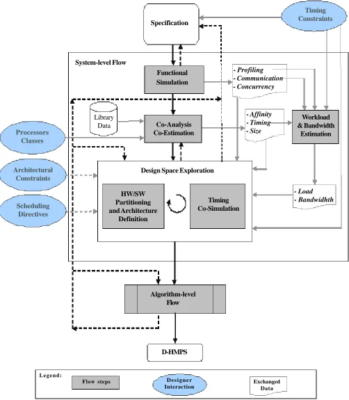
The reference system-level design flow (a slight extension of the one in [20]) is shown in Figure 1: it reports the main co-design steps that are briefly described in the following.
2.1 Specification
The entry point of the proposed co-design flow is the specification of the system functionalities, with related timing constraints, by means of an homogeneous executable specification language to avoid polarizing the design towards hardware or software.
2.2 Functional Simulation
The first step is the Functional Simulation [17] [18] where the system functionalities are simulated to check their correctness with respect to typical input data sets. During this step, important data characterizing the dynamic behavior of the system are also collected: Profiling,Communication and Concurrency.
2.3 Co-Analysis and Co-Estimation
Figure 1. The reference system-level co-design flow
2.4 Load and Bandwidth Estimation
Combining data provided by previous steps (timing and profiling) under a time-to-completion constraint allows the estimation of the Load [17] associated with the execution of each system functionality on a single COTS GPP system (i.e. the worst case).
Specification
System-level Flow
Timing Constraints
Functional Simulation
Co-Analysis Co-Estimation Library
Data
- Profiling - Communication
- Concurrency
- Affinity - Timing
- Size
Workload & Bandwidth
Estimation
Design Space Exploration
HW/SW Partitioning and Architecture
Definition
Timing Co-Simulation
- Load - Bandwidhth
Algorithm-level Flow
D-HMPS
Processors Classes
Architectural Constraints
Scheduling Directives
Exchanged Data D e s i g n e r
Interaction Flow steps
Finally, combining communication and timing data it is possible to estimate the Bandwidth needed to the different functionalities to communicate while fulfilling a time-to-completion constraint.
2.5 Design Space Exploration
Finally, the flow reaches the Design Space Exploration step that is constituted by two iterative tasks: HW/SW Partitioning and Architecture Definition [7], and Timing Co-Simulation [17] [18]. All the data produced in previous steps are used to drive the process, together with additional information provided by the designer. The partitioning and architecture definition task explores the design space (it is based on a genetic algorithm as described in section V) looking for feasible mapping/architecture items suitable to satisfy imposed constraints. Then, the timing co-simulation task considers the suggested mapping/architecture items to actually check for timing constraints satisfaction.
2.6 Algorithm-Level Flow
When the mapping/architecture item proposed by the design space exploration is satisfactory, it is possible to implement the Figure 2. CSP and a possible related PING
channel
ch4
ch5
ch6 ch2
ch1
ch3
EN_OUT1 EN_IN1
P1 P2
P3 P4
P1 P3 P4
P3.1
P2 P4.1
P1.1 P1.2
system. For this, the SW system functionalities will be typically transformed in C code while the HW system functionalities will be transformed in synthesizable HDL code or implemented by means of existing COTS component. Moreover, if proper models are available (i.e. Instruction Set Simulators or HDL/TLM descriptions for processors, and bit-level or TLM models for interconnections) it is also possible to build a virtual prototype of the system to check its properties at a lower level of details prior to proceed with its physical realization.
3. Specification
The entry point of the proposed co-design flow is the specification of the desired system functionalities. This aspect introduce some modeling issues: the adopted model of computation (MoC), related specification languages, and the “internal models” of representation to be used to allow a proper tool-chain to make automatic analysis and transformations.
In this work, the system functionalities specification is assumed to be based on the CSP model of computation (Communicating Sequential Processes [14] [24]) and described by means of an homogeneous executable specification language suitable to support such a MoC (e.g. OCCAM, HandelC, SystemC, etc…). Once selected a specification language, in order to automatically analyze the specification, two internal models at different levels of abstraction are needed:
- A statement-level internal model, that strictly depends on the chosen specification language and on parsers used to analyze the specification at a level detailed enough to make reliable estimations and to compute metrics (i.e. the second step of the flow in Figure 1);
- A procedure-level internal model, possibly independent from specification languages, used to explore the design space.
Since the main internal model for the design space exploration is the procedure-level one, the approach presented in this work is based on the Procedural Interaction Graph (PING [7]). The Procedural Interaction Graph is a formalism that provides information about the relationships among procedures and the exchanged data. Such a graph is suitable for representing a coarse-grain view of system functionalities taking into account communications, synchronizations and concurrency issues. By means of a PING it is possible to represent a CSP considering also possible decompositions of each process. Figure 2 shows a CSP (with 6 processes and 6 channels) and a possible PING where processes have been decomposed by means of procedures.
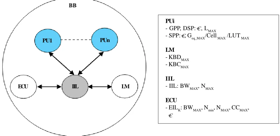
Figure 3. The Basic Block and its characterization parameters PUi
- GPP, DSP: , LMAX
- SPP: , Geq_MAX/Cell MAX /LUT MAX
LM - KBDMAX - KBCMAX
IIL
- IIL: BWMAX, NMAX
ECU
- EILK: BWMAX, Nmin, NMAX, CCMAX, PUn
PU1
ECU IIL LM
BB
C −− −−C
4. Target HW Architecture
The target HW architecture selected for the proposed extended methodology is an heterogeneous multi-processor one. In particular, each processor could be also homogeneous multi-core. The memory is supposed to be shared between cores in the same processor and distributed between processors.
The whole architecture is so composed of a proper interconnections of some instances of different Basic Blocks (BB, Figure 3). Moreover, each BB is composed of three main elements: a set of Processing Units (PU), a Local Memory (LM) and an External Communication Unit (ECU). The elements in the same BB share the LM and they are interconnected by an Internal Interconnection Link (IIL, typically a shared bus mastered by the PUs while the ECU is a memory-mapped SPP slave). It is worth noting that having more PUs in single BB allows to model shared-memory multi-core architecture while considering more than one BBs allow to model also distributed-memory multi-processor ones.
In the actual methodology, PUs could belong only to one of three different processor classes (i.e. COTS GPP, COTS DSP and Custom SPP) where GPP and DSP are characterized by the cost ( ) and the maximum load LMAX, while SPP is characterized by the cost ( ) and the max number of equivalent gates Geq_MAX(in the case of a fixed family of reconfigurable logic the last metric should be changed with the max number of available cells or LUT). LM is the local memory directly addressable by the PUs
Figure 4. Architecture Graph BB4
BB5 BB6
BB1
BB2
IL3.1
IL2.1 IL1.1
DSP2 GPP3
GPP2
DSP1
SPP1 BB3 GPP1 IL1.2
Corel 1
Corel 2
Corel 1
Corel 2
Corel 3
Corel 4
C −−
belonging to the same BB and it is characterized by a cost ( ) and max size for data (KBDMAX ) and max size for code and parameters (KBCMAX ). ECU is characterized by the set of External Interconnection Links (EIL) that it is able to manage. Moreover, each EIL is characterized by the following parameters:
- The max available bandwidth (BWMAX );
- The min/max number of BBs that should/could use an EIL instance (NMIN and NMAX );
- The max number of allowed concurrent communications (CCMAX ); - The cost ( ).
Finally, to consider the optimal number of PUs in a single BB, the Internal Interconnection Link is characterized by:
- The max available bandwidth (BWMAX);
- The max number of PUs that could be connected to it (NMAX ).
So, given some instances of BBs and interconnecting them by means of some instances of EILs it is possible to define a feasible Figure 5. The two-phases DSE approach
Annotated Specification
(PING)
PAM1
- Partial Architecture
Number and type of processors/ cores
- HW/SW Partitioning - Mapping
BB Interaction
Graph
- Final Architecture
Number and type of processors Number and type of interconnection links
Topology
- HW/SW Partitioning - Mapping
PAM2 1st Phase
2nd Phase
C −−
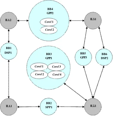
dedicated heterogeneous parallel architecture on which the system functionalities can be mapped to. Such an architecture could be so represented by means of a hierarchical architecture graph [16]. For example, Figure 4 (as wells as Figure 3 for a single BB) shows an architecture graph for an heterogeneous multi-processor/multi-core architecture composed of 6 instances of heterogeneous BBs. Moreover, GPP1 and GPP2 are also homogeneous multi-cores. Finally, such BBs are connected by means of three types of external interconnections links (i.e. two instances of IL1, and one instance of IL2 and IL3).
5. Design Space Exploration
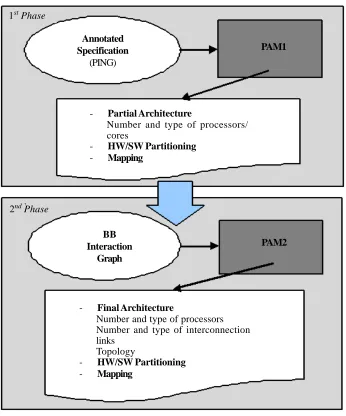
This section explains in detail the design space exploration approach proposed for the “HW/SW Partitioning and Architecture Definition” task of Figure 1, with the adopted heuristic, metrics and cost functions. The final goal is the automatic identification of an HW/SW partitioning of the system functionalities, the automatic selection of an heterogeneous parallel architecture, and a mapping of the partitioned entities onto it, able to optimize the adopted cost function. The proposed approach is decomposed into two sequential phases, as shown in Figure 5.
5.1 First Phase
The first phase is mainly related to computation issues (the approach in [7] has been extended to consider the new target HW architecture). The internal-model representing the specification, annotated during the Co-Analisys&Co-Estimation step (Figure 1), is provided as input to the PAM1_v2 (i.e. Partitioning, Architecture Definition and Mapping Phase 1) tool. In particular, each PING procedure is annotated with several metrics:
- Load imposed by each procedure to a single COTS GPP under a time-to-completion constraint: l;
- Bandwidth needed to communicate with other procedures while fulfilling a time-to-completion constraint: b; - Size for HW and SW implementations: s (KBD and KBC bytes, and Geq/cells/LUT);
- Affinity of each procedure towards a set of processor classes (actually only COTS GPP, COTS DSP and Custom SPP): a
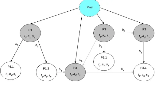
Figure 6. Annotated Procedural Interaction Graph
So, starting from an annotated PING (Figure 6 shows an annotated version of the one in Figure 2) the first phase goal is to determine number and type of BBs/PUs and a mapping of PING procedures onto them trying to:
Main
P3
P1 P3
I1, a1, s1 I4, a4, s4 I3, a3, s3
P3
I2, a2, s2 P1.1
I1, a1, s1
P1.2
P3.1
I
6, a6, s6
I
7, a7, s7
P3.1
I8, a8, s8
b1 b
2
b4
b5
b6
b3
- Minimize the cost of the set of BBs
• The max number of instances allowed for each kind of PUs and the max number of PUs allowed in a single BB could be provided as an architectural constraints by the designer
- Keep the load of each PU near but under its LMAX
- Minimize communications between different BBs - Exploit the affinity between PUs and the procedures
- Keep the used size near but under KBDMAX , KBCMAX (for GPP/DSP) or Geq_MAX / CellMAX /LUTMAX(for SPP) - Exploit the explicit parallelism expressed in the PING
- Keep each IIL bandwidth under but near its BWMAX
- Keep the number of PUs inside a single BB using the same IIL under but near its NMAX
by minimizing a cost function by means of a genetic approach [15] where each individual of the population represents a possible partial mapping/architecture item. Such a cost function is composed of several terms related to the following system-level metrics [7] that are evaluated for each individual during the genetic evolution (a value of 0 indicates the best situation):
- Affinity Index (IA): [0, 1]
• Affinity between the features of the procedures and the processors on which they have been mapped to
- Load Indexes (IL): [0, 1]
• Balancing of the workload over the available GPP and DSP with respect to LMAX
- Communication Index (IC): [0, 1]
• Exchanged data size between procedures mapped onto different BBs (i.e. exchanged data size between BBs)
- Physical Cost Index (I ): [0, 1] • Cost of the solution
- Size Indexes (IKB , IGeq): [0, 1]
• Memory (GPP/DSP) or resources (SPP) utilization
- Concurrency (Parallelism) Index (IP): [0, 1]
• Exploitation of the concurrency expressed in the CSP
- Internal Saturation Index (IIB): [0, 1]
• Respect of the max bandwidth offered by each IIL
- Internal Exploitation Index (IIE ): [0, 1]
• Respect of the max number of PUs inside each BB that can use an IIL instance
By combining the previous indexes a linear cost function has been built to compare different partial mapping/architecture item:
CF = wA . IA + wL . IL + wc . IC + w• . I• + wKB . IKB
+ wGeq . IGeq+ wP . IP + wIB . IIB + wIE . IIE
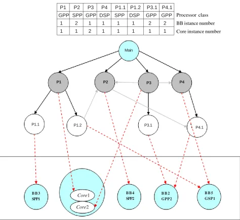
where the weights w (belonging to the interval [0,1]) are used to identify individuals that better tradeoffs different parameters. The structure of an individual is represented by an entry for each PING procedure: each procedure is associated with a class of BB/PU, a BB instance number, and a core instance number. Figure 7 shows a possible individual instance with its corresponding partial mapping/architecture for the PING of Figure 6. In general, the mapping could be formally expressed as done in [16].
The initial population is randomly generated and during its evolution the algorithm minimizes the cost function following the
classical rules of genetic algorithms. In particular, each cross-over operation generates two new individuals combining two existing ones as shown in Figure 8 while the mutation operation changes classical rules of genetic algorithms. In particular, each
cross-over operation generates two new individuals combining two existing ones as shown in Figure 8 while the mutation
operation changes randomly class and/or instance numbers associated with a randomly selected procedure.
During the evolution, the individuals that score the worst values tend to be replaced by better ones. Several parameters in the algorithm (e.g. population size, number of generations, mutation probability, etc…) allow a wide exploration of the design space, with the goal to avoid local minima. It is worth noting that, to avoid complexity explosion while coping with large system specifications, it is possible to exploit the clustering approach already described in [7] (currently not implemented in the PAM1_v2 tool).
Figure 7. An individual and its corresponding architecture
Core1
Core2
P1.1 P1.2 P3.1
P4.1
P1 P2 P3 P4
Main
B B 3 SPP1
B B 4 SPP2
B B 2 GPP2
B B 5 GSP1
Processor class BB istance number Core instance number P1 P2 P3 P4 P1.1 P1.2 P3.1 P4.1
5.2 Second Phase
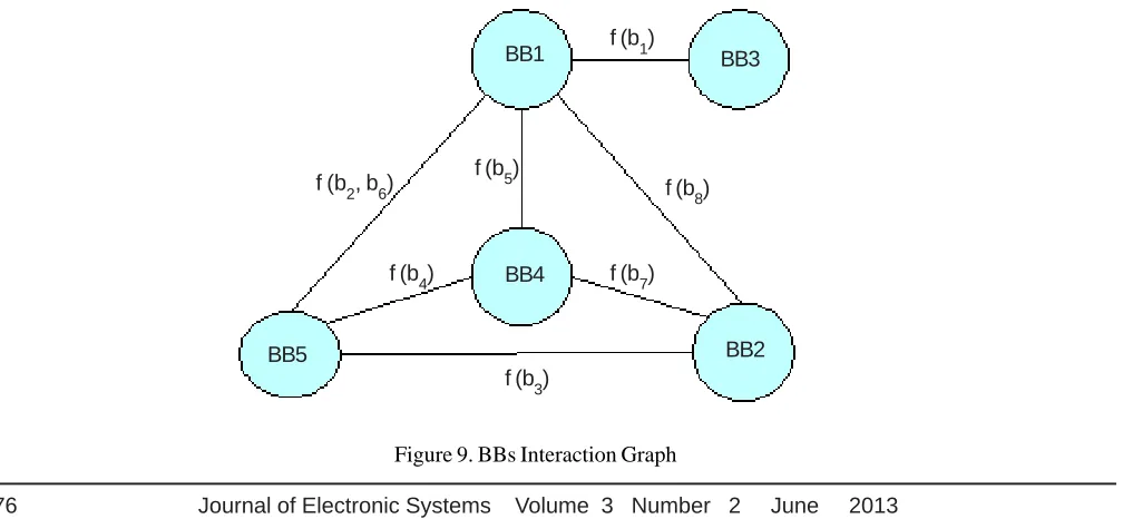
The output of the first phase is mainly related to the computation aspects of the architecture: number and type of BB/PUs and the mapping of each PING procedure onto them. The starting point of the second phase is the so called BBs Interaction Graph
(BING), an internal model used to represent the partial system obtained at the end of the first phase. It allows to shift from a procedure-oriented to a BB-oriented view of the system while keeping the information related to the BBs that need to communicate. Such BBs are so connected by edges that are annotated depending on a proper function of the bandwidth required by each procedure mapped onto each BBs (e.g. the sum to represent the worst-case scenario, the average to represent an intermediate situation, etc.). Figure 9 represents the BING related to the architecture of Figure 7 for the PING of Figure 2. Such a model is provided as input to the PAM2_v1 (i.e. Partitioning, Architecture Definition and Mapping Phase 2) tool (Figure 5).
Figure 9. BBs Interaction Graph Random position
Parents
Children
P1 P2 P3 P4
1 2 2 1
GPP HW HW GPP
1 1 2 1
P1 P2 P3 P4
2 2 1 3
GPP HW HW GPP
1 1 1 1
P1 P2 P3 P4
2 2 2 1
GPP HW HW GPP
1 1 2 1
P1 P2 P3 P4
1 2 1 3
GPP HW HW GPP
1 1 1 1
f (b1)
f (b8)
f (b7)
f (b 3) f (b4)
f (b5) f (b2, b6)
BB1 BB3
BB2 BB4
BB5
So, starting from a BING the goal is to determine number and type of EILs between BBs in order to: - Minimize cost of the set of EILs
• The max number of instances for each EIL can be specified by the designer as an architectural constraints
- Keep the bandwidth of each EIL under but near BWMAX
- Keep the number of BB using each EIL under but near NMAX (and >= NMIN)
- Keeping feasibility by respecting ECUs characterization
by minimizing a cost function by means of a genetic approach where each individual of the population represents a possible complete (i.e. enriched with interconnections/topology info) architecture/mapping item. Such a cost function is composed of several terms related to the following system-level metrics that are evaluated for each individual during the genetic evolution (a value of 0 indicates the best situation):
- Saturation Index (IB): [0, 1]
• Respect of the max bandwidth offered by the EIL
- Exploitation Index (IE): [0, 1]
• Respect of the min/max number of BBs that can use an EIL instance
- Physical Cost Index (I ): [0, 1]
• Cost of the solution
- Concurrent Communications Index (ICC ): [0, 1]
• Respect of the max number of concurrent communications allowed by the EIL
- Feasibility Index (IF): [0, 1]
• A pair of ECUs should be able to manage at least a common IL in order to allow the related BBs to directly communicate: such an index indicates how much of the actual communications are unfeasible
By combining the previous indexes a linear cost function has been built to compare different interconnections/topology item:
CF = wB . IB + wE . IE + w . I + wCC . ICC + wF . IF
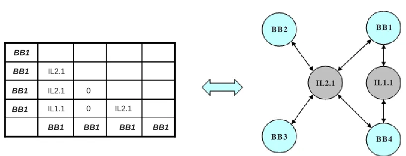
Figure 10. An example of individual and corresponding architecture graph
In order to perform the exploration of the design space, the initial population is randomly generated, while during its evolution the algorithm performs the optimizations that minimize the cost function following the classical rules of genetic algorithms. In particular, it is very important to analyze the adopted cross-over approach: starting from two individuals it is possibly to apply both a vertical (Figure 11 left) and an horizontal (Figure 11 right) cut in order to preserve respectively columns and rows. In this
B B 2 B B 1
B B 3 B B 4
IL2.1 IL1.1
BB1
BB1
BB1
BB1
BB1 BB1 BB1 BB1
IL2.1
IL2.1
IL1.1 IL2.1
0
0
C −−
way, each couple involved in the cross-over gives rise to 4 new individuals so spreading and accelerating the design space exploration.
Figure 11. Cross-over
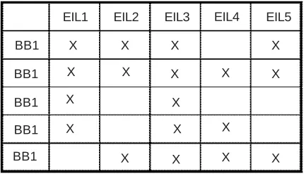
Unfortunately, such an approach could give rise to unfeasible solutions so the feasibility of the children has to be checked and properly took into account: unfeasible solutions will get an higher cost function and so they will be probably removed from the population. However, there is always the possibility of a mutation process giving rise to better individuals that otherwise could be difficult to obtain (i.e. avoiding local minimum). In order to check such a feasibility, it is needed an ECU characterization with respect to the BBs belonging to the BING. This is obtained by defining a proper ECU Characterization Matrix (ECUCM) that explicitly indicates the EILs that each BB is able to manage. A generic example of such matrix is shown in Figure 12.
Figure 12. ECU Characterization Matrix
5.3 Illustrative Example
To highlight the main features of the proposed DSE approach an illustrative example is reported in the following. Let be the CSP specification the one shown in Figure 2 and the related annotated PING the one shown in Figure 6. Let be the annotated values of ai , li , si and bi such that the PAM1_v2 tool would provide as output of the first phase the mapping/architecture shown in Figure 7. The related BING is then the one shown in Figure 9.
Now, let fix some values in order to make the tool PAM2_v1 able to apply the second phase and to provide some results. First, it is needed to assign some values to the bandwidths (e.g. MB/s) in the BING:
- BW1= f (b8) = 250
- BW2= f (b1) = 200
IL0.0 IL0.1 IL1.0 IL1.0 IL1.1 0 IL0.0 IL0.1 IL1.0 0 IL0.0 IL1.0 IL0.1 IL1.0 0 IL1.1 IL1.0 IL0.0 IL0.1 IL1.0 BBB0 BBB1 BBB2 BBB0 BBB1 BBB2 BBB1 BBB0 BBB0 BBB1 BBB2
BBB2 BBB1 BBB2
BBB0 BBB1 BBB2 BBB0 BBB0 BBB1 BBB2
BBB0 BBB1 BBB2
BBB0 BBB1 BBB2 BBB0 BBB1 BBB2
BBB0 BBB1 BBB2 BBB0
BBB1
BBB2
BBB0 BBB1 BBB2
BBB0
BBB1
BBB2
BBB0 BBB1 BBB2
0 IL1.1 IL1.0 IL1.1 BB1 BB1 BB1 BB1 BB1
X X X X
X X
X X X
X
X
X X X
X X
X
X
- BW3= f (b5 ) = 200
- BW4= f (b7 ) =150
- BW5= f (b2, b6 ) = 250
- BW6= f (b3 ) = 50
- BW7= f (b4 ) = 50
Then, it is needed to characterize the possible external interconnections links (i.e. max bandwidth, min and max number of processors, max number of concurrent communications and relative cost), for example:
- EIL1= (300, 2, 2, 1, 1)
- EIL2= (400, 2, 2, 2, 2)
- EIL3= (250, 3, 8, 1, 3)
- EIL4= (400, 3, 6, 1, 4)
- EIL5= (200, 4, 80, 4, 5)
Actually, from an implementation point of view (i.e. a lower level of abstraction), the different EILs could be representative of a Figure 13. Final system: HW/Partitioning, Architecture and Mapping
P1.1
P1.2 P3.1
P4.1
P1
P2 P3
P4
B B 3 SPP1
B B 4 SPP2 B B 2
GPP2
B B 5 GSP1 Core1
Core2 B B 1 GPP1
IL1.1 IL1.2 IL1.3 IL2.1
point-to-point communications (EIL0/EIL1, e.g. GPIO or UART based), of a standard bus (EIL2/EIL3, e.g. I2C or SPI), or of a mesh (EIL4, e.g. crossbar or omega switch). Next, it is needed to associate such EILs with the ECUs that are able to manage them: for example let keep valid the matrix of Figure 12. Hence, the second phase of the system design exploration is performed introducing in the cost function previously described the following trade-off weights:
WB = WE = WCC = 0.2, W = 0.4,WF =100
and imposing, for example, the following architectural constraints: max number of instances for each kind of IL equal to 4.
Starting from a population of 1000 individuals (with an upper bound of 10000) and executing the GA for 10000 generations, the
PAM2_v1 gives rise at the following best result:
IB= 0.42, IE= 0.1, I = 0.14, ICC= 0.1, IF= 0, CF= 0.18
associated to the mapping/architecture item shown in Figure 13.
Such an item reflects the characterizations of EILs (i.e. bandwidth, number of processors, etc…) and ECUs (i.e. characterization matrix), and represents a sub-optimal optimization for the adopted cost function. So, it represents a suggestion for the final system implementation.
Now, with the goal to check the behavior of the algorithm when changing some parameters, let modify the EILs characterization introducing a new high-performance EIL2 link at the same price:
- EIL2 = (1000, 2, 8, 4, 2)
Starting again from a population of 1000 individuals (with a bound of 10000) and executing the GA for 10000 generations, the
PAM2_v1 tool gives rise at the following best result:
IB = 0.28, IE= 0.19, I = 0.07, ICC= 0.11, IF= 0, CF = 0.185 Figure 14. New final system: HW/Partitioning, Architecture and Mapping
P1.1
P1.2
P1.1
P2 P3
P4
B B 3 SPP1
B B 4 SPP2 B B 2
GPP1
B B 5 GSP1 IL1.1
IL2.1
P4.1 P3.1
Core1
Core2 BB1
C −−
C −−
associated to the architecture/mapping item shown in Figure 14.
Such an item meets again all the constraints while exploiting the new link features by suggesting a cheapest architecture.
6. Conclusions
This paper has coped with the problem of hw/sw co-design of dedicated digital systems based on heterogeneous multi-processor architectures. In particular, it has proposed an extension of a previous system-level design space exploration approach able to suggest to the designer an HW/SW partitioning of the application specification and a mapping of the partitioned entities onto an automatically selected heterogeneous multi-processors/multi-core architecture. The approach is currently under validation by means of proper tools by checking the consistency of the adopted metrics and heuristics. The preliminary experimental results are encouraging and justify further research efforts in this direction.
7. Acknowledgements
This work has been partially supported by the following ARTEMIS projects:
- PRESTO (GA n. 269362) - CRAFTERS (GA n. 295371)
References
[1] Xilinx Virtex-II Pro, http://www.xilinx.com, (2013). [2] Nexperia Platform, www.nxp.com, (2013). [3] OMAP Platform, www.omap.com, (2013).
[4] SH Mobile Series, http://www.renesas.com, (2013).
[5] Haubelt, C., Schlichter, T., Keinert, J., Meredith, M. (2008). SystemCoDesigner: Automatic design space exploration and rapid pro totyping from behavioral models, Design Automation Conference. DAC. 45th ACM/IEEE.
[6] Zai Jian Jia, Pimentel, A. D., Thompson, M., Bautista, T., Nunez, A. (2010). NASA: A generic infrastructure for system-level MP-SoC design space exploration, Embedded Systems for Real-Time Multimedia (ESTIMedia), 8th IEEE Workshop on. [7] Pomante, L., Sciuto, D., Salice, F., Fornaciari, W., Brandolese, C. (2006). Affinity-Driven System Design Exploration for Heterogeneous Multiprocessor SoC. IEEE Transactions on Computers, 55 (5), May.
[8] Thilo Streicher, Michael Glab, Christian Haubelta, Jürgen Teich. (2007). Design space exploration of reliable networked embedded systems. Journal of Systems Architecture 53, p. 751–763, January.
[9] Ascia, G., Catania, A., Di Nuovo, G., Palesi, M., Patti, D. (2007). Efficient design space exploration for application specific systems-on-a-chip, J. Syst. Archit., 53 (10) 733–750, Oct.
[10] Holzer, M., Knerr, B., Rupp, M. (2007). Design space exploration with evolutionary multiobjective optimization, In: Proc. Ind. Embedded Syst., p. 125–133.
[11] Palermo, G., Silvano, C., Zaccaria, V. (2008). An efficient design space exploration methodology for on-chip multiprocessors subject to application-specific constraints, in Proc. SASP, p. 75–82.
[12] Haubelt, C., Schlichter, T., Keinert, J., Meredith, M. (2008). System Co-Designer: Automatic design space exploration and rapid prototyping from behavioral models, In: Proc. Design Automat. Conf, p. 580–585.
[13] Vahid, F., Givargis, T. (2002). Embedded System Design: A Unified HW/SW Introduction. John Wiley & Sons. [14] Hoare, C.A.R. (1978). Communicating sequential processes. Communications of the ACM, 21 (8) 666–676, August . [15] Mitchell. (1996). An Introduction to Genetic Algorithms, M. I. T. Press.
[17] Pomante, L. (2002). System-Level Co-Design of Heterogeneous Multiprocessor Embedded Systems, Ph.D Thesis, DEI, Politecnico di Milano.
[18] Sciuto, D., Salice, F., Fornaciari, W., Pomante, L. (2001). Hw/Sw Cosimulation for Fast Design Space Exploration of Multiprocessor Embedded Systems, Canadian Journal of Electrical and Computer Engineering (CJECE), 26 (3/4) 135-140. [19] Abildgren, R., Saramentovas, A., Ruzgys, P., Koch, P., Le Moullec, Y. (2007). Algorithm-architecture affinity-parallelism changes the picture. In: Proceedings on the Design and Architectures for Signal and Image Processing, Grenoble, France, November.
[20] Pomante, L. (2011). System-Level Design Space Exploration for Dedicated Heterogeneous Multi-Processor Systems. IEEE International Conference on Application-specific Systems, Architectures and Processors, September.
[21] Allara, A., Brandolese, C., Fornaciari, W., Salice, F., Sciuto, D. (1998). System-level performance estimation strategy for sw and hw, Computer Design: VLSI in Computers and Processors. ICCD ’98. In:Proceedings. International Conference on 98, Oct. [22] An area estimation methodology for FPGA based designs at systemc-level, Brandolese, C., Fornaciari, W., Salice, F., Design Automation Conference. (2004). In: Proceedings. 41st, p. 129 – 132.
[23] Brandolese, C. (2008). Source-Level Estimation of Energy Consumption and Execution Time of Embedded Software, Digital System Design Architectures, Methods and Tools, 2008. DSD ’08. 11th EUROMICRO Conference on , p.115-123, 3-5 Sept.