13
Available online at www.ijiere.com
International Journal of Innovative and Emerging
Research in Engineering
e-ISSN: 2394 – 3343 p-ISSN: 2394 – 5494
Design of Compact Self-Locking Lifting Device by Application
of Twin Worm Arrangement
Mr.Vikrant D. Sathe1
a, Prof. Abhay.M.Kalje2
b1a ME (Mech-Design), N B Navale Sinhagad College of Engineering, Kegaon, Solapur, Solapur University,India. 2b Associate Professor, N B Navale Sinhagad College of Engineering, Kegaon, Solapur, Solapur University,India
.
ABSTRACT:
In machine tool applications it is often required to lift heavy work-pieces using conventional winches or chain blocks which may require assistance from two or more workers for mere loading the work-piece on to machine which is rather contradictory to the one man-multi machine concept. Worm gears are one of the few gear systems that can be made self locking, but at the expense of efficiency, they seldom exceed 45% efficiency, when made self locking. This paper describes an efficient mechanism for lifting the load with the help of twin worm arrangement.
Keywords: Self Locking, Efficiency, Material Handling, Lifting Devices, Twin Worm.
I. INTRODUCTION
Material handling equipment (MHE) is used for the movement and storage of material within a facility or at a site. MHE can be classified into the following five major categories:
Transport Equipment: Equipment used to move material from one location to another (e.g., between workplaces, between a loading dock and a storage area, etc.). The major subcategories of transport equipment are conveyors, cranes, and industrial trucks. Material can also be transported manually using no equipment.
Positioning Equipment: Equipment used to handle material at a single location so that it is in the correct position for subsequent handling, machining, transport, or storage. Unlike transport equipment, positioning equipment is usually used for handling at a single workplace. Material can also be positioned manually using no equipment.
Unit Load Formation Equipment: Equipment used to restrict materials so that they maintain their integrity when handled a single load during transport and for storage. If materials are self-restraining (e.g., a single part or interlocking parts), then they can be formed into a unit load with no equipment.
Storage Equipment: Equipment used for holding or buffering materials over a period of time. Some storage equipment may include the transport of materials. If materials are block stacked directly on the floor, then no storage equipment is required.
Identification and Control Equipment: Equipment used to collect and communicate the information that is used to coordinate the flow of materials within a facility and between a facility and its suppliers and customers. The identification of materials and associated control can be performed manually with no specialized equipment. Lifting equipment, also known as lifting gear, is a general term for any equipment that can be used to lift loads. This includes jacks, block and tackle, hoists, rotating screws, gantries, A frames, gin poles, shear legs, sheer leg, windlasses, lifting harnesses, forklifts, hydraulic lifting pads, air lift bags, and cranes. Lifting equipment can be dangerous to use, and is the subject of safety regulations in most countries
II. PROBLEMDEFINITION
The term self locking as applied to gear systems denotes a drive which gives the input gear the freedom to rotate the output gear in either directions but the output gear locks with input when an outside torque attempts to rotate the output in either direction. This characteristic is often sought after by designers who want to be sure that the loads on the output side of the system cannot affect the position of the gears. Worm gears are one of the few gear systems that can be made self locking, but at the expense of efficiency, they seldom exceed 45% efficiency, when made self locking.
III. PROBLRMSTATEMENTATSPONSEREND M/s Paramount Industries 36/5 MIDC ROAD, Morwadi, Pimpri, Pune -18
work-14 pieces is done using a Chain Winch , which requires two or more labour to handle the system. Problem in hand is to develop a compact lifting device to be operated using 12 Volt DC power, system to be button operated with easy loading and unloading facility so that operator can single handed load or unload the work-piece onto machine.
IV.LITERATUREREVIEW
The generation of face worm gear drives of all types of existing design is based on application of a hob for generation of the face-gear. The hob is similar to the worm of the drive. The disadvantage of such method of generation is the low precision of a hob used as a generating tool especially in the case of small dimensions of hob. The new geometry proposed in this paper is based on application of head-cutters or head grinding tools that have higher precision and larger dimensions in comparison with a hob and enable to provide a higher productivity of the process of generation [1].
In most of the gear drives, when the driving torque is suddenly reduced as a result of power off, torsional vibration, power outage or any mechanical failure at the transmission input side, then gears will be rotating either in the same direction driven by the system inertia, or in the opposite direction driven by the resistant output load due to gravity, spring load, etc. The latter condition is known as back driving. However, there are also solutions in gear transmission that prevent inertial motion or back driving using self-locking gears without any additional devices.
The term self locking as applied to gear systems denotes a drive which gives the input gear the freedom to rotate the output gear in either directions but the output gear locks with input when an outside torque attempts to rotate the output in either direction. Worm gears are one of the few gear systems that can be made self locking, but at the total of efficiency, they rarely exceed 40% efficiency, when made self locking. The experiment is carried in the laboratory with sufficient small prototype model.[2]
Gear box has to produce maximum power with minimum weight. In many real-life problems, objectives under consideration conflict with each other, and optimizing a particular solution with respect to a single objective can result in unacceptable results with respect to the other objectives. Multi-objective formulations are realistic models for many complex engineering optimization problems. A reasonable solution to a multi-objective problem is to investigate a set of solutions, each of which satisfies the objectives at an acceptable level without being dominated by any other solution. In the paper, [3] Ant Colony Optimization was developed specifically for a Worm gear drive problem with multiple objectives.
V. CONSTRUCTION OF COMPACT SELF LOCKING LIFTER
The zero slip lifter comprises of the following parts:
Lifter Drum: The lifter drum is the component on which the rope is wound with the object to lift the load.
Bearing housing: The bearing housing bracket holds the bearing 6020 with 100 mm internal diameter and 150 mm outer diameters and 24 mm width. The bearing housing is mounted on MS channel supports :
Left hand internal worm gear : This part is left hand threaded with trapezoidal threads of 10mm pitch and lead angle of 1.8 degree
Gear: The spur gear with 1.5 module 74 teeth is mounted on the threaded worm shaft to transmit power from the motor pinion to the threaded worm to drive the ring gear.
Right hand external thread shaft : This enables the threaded ring to drive internal gear but at the same time acts as a self lock as the internal ring gear cannot drive the input worm
15
VI. DESIGN OF PARTS
Here the theoretical design and analysis of parts is discussed, which is as below.
1.Design Of Spur Pinion & Gear For Drive From Motor To Main Shaft[4] Motor Power = 6 watt Speed = 92 rpm
Torque = 60 x P / 2 π N = 60 x 6 / 2 π 92 = 0.62 N-m
After reduction using spur gear pair max torque = 0.62 x 2.778 =1.72N-m
Drive As Gear And Pinion Arrangement
Maximum load =Maximum torque / Radius of gear, Maximum torque = 1.72 N-m, No of teeth on pinion= 18, No of teeth on gear = 50, Module = 1.5 mm
Radius of gear by geometry = (50 x 1.5) /2=37.5mm Maximum load = T/r =1.72 x 10³ /37.5=45.9. N b = 10 m Material of spur gear and pinion = EN24
Sult pinion = Sult gear = 800 N/mm2
Considering factor of safety = 2, Sult = 400 N/mm2 , Service factor (Cs) = 1.5
Pt =( W x Cs) =69 N.
Peff = 69 N (as Cv =1 due to low speed of operation)
Lewis Strength equation [4] WT = Sbym
Where;
Syp = 260
As Syp < Sys pinion is weaker
WT = (Syp) x b x m =260 x 10m x m WT= 2600m2---(B)
Equation (A) & (B) 2600m2 =69
m=0.16mm
Selecting standard module = 1.5 mm Hence gear pair dimensions are as follows,
Pinion: 18 teeth .1.5 module, integral with worm wheel shaft in power widow motor shaft.
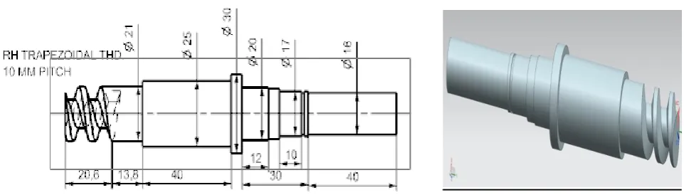
2.Design of External Threaded Shaft:
Fig. 2 Dimensions and Modeling of External Threaded Shaft
Check For Torsional Shear Failure of Shaft.
Torque is applied at the driven gear mounting point on the shaft which 16mm in diameter,
16 Fig. 3 Analysis of Right handed Threaded Shaft at Gear Mounting Side
3.Design of Lifter Drum Shaft
Material Selection from PSG Design Data Book
Table 1. Mechanical properties of material
Designation Ultimate Tensile strength N/Mm2 Yeild Strength N/mm2
EN 9 600 480
Let
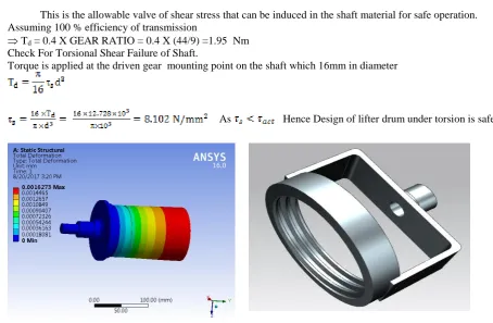
This is the allowable valve of shear stress that can be induced in the shaft material for safe operation. Assuming 100 % efficiency of transmission
Td = 0.4 X GEAR RATIO = 0.4 X (44/9) =1.95 Nm Check For Torsional Shear Failure of Shaft.
Torque is applied at the driven gear mounting point on the shaft which 16mm in diameter
As Hence Design of lifter drum under torsion is safe.
Fig. 4 Analysis and modeling of Lifter Drum
From the above analysis it is found that the theoretical method and Von-Misses stress are well below the allowable limit, hence the design of Lifter Drum is safe. The Lifter Drum shows negligible deformation under the action of system of force
REFERENCES
17 [2] Prof. P.B. Kadam, Prof. M.R. Todkar “Improvement in the Design & Manufacturing of Twin Worm Self Locking
Technique and applications”, IOSR Journal of Engineering May. 2012, Vol. 2(5) Page no.1224-1233.
[3] Padmanabhan. S., Chandrasekaran. M. and Srinivasa Raman. V. “Design Optimization of Worm Gear drive”, International Journal of Mining, Metallurgy & Mechanical Engineering (IJMMME) Volume 1, Issue 1 (2013), Page no.57-61.