Vol. 4, Issue 1, January 2019
NUMERICAL ANALYSIS OF EFFECTS OF
DIVEREGENCE ANGLE CHANGE ON A
SUPERSONIC FLOW THROUGH A DE
LAVAL NOZZLE AND ITS ANALYTICAL
VERIFICATION
Vishnu R [1], Arun V T [2], Rammohan R [3]
[1] [2][3]
Assistant Professor, Department Of Mechanical Engineering, Sarabhai Institute Of Science And Technology, Velland, Thiruvananthapuram,
Abstract:The aim of this study is to develop a stable as well as robust computational model of a convergent-divergent nozzle that can be used to further our understanding on the complex flow behaviours such as shocks, flow separation etc. The values of temperatu re, pressure and velocity should be made available at every section of the nozzle so as to design the nozzle shape, insulation and cooling arrangements. Based on the problem definition a model of the said nozzle is created using Solidworks. The dimensions are available as per the problem definition. This model will be imported into a CFD environment to find the solutions of interest numerically. This data needs verification or validation by experimental means. Since experimental methods are beyond the scope of this paper, only the analytical verifica tion part using known theoretical formulations regarding 1D nozzle flow are taken .The theoretical formulae and assumptions involving .the nozzle calculations are to be therefore gathered before to be able to verify the computational values obtained from the simulation. The theoretical calculations of pressure, velocity and temperature values are performed and tabulated, which is followed extensively in this paper for verification purposes. Also if the values obtained from the simulation conform to the known values, the geometry of the model is changed to study the effects it has on the variables of interest. The results and the ensuing conclusions are as follows: With the in crease of divergence angle the Mach number tends to rise and small shocks developed in the flow seem to be die out. This trend goes on with the increase of Mach number up to a limit, say beyond 20 deg of divergence angle, with still the area ratio kept constant, it has been observed that Mach number decreases very profoundly. Mass balance ensured that the simulation conforms to conservation of mass. CFD considers the factors like boundary layer effects, shock waves, radial velocity component and so on, which leads to some minor variance from theoretical results. The variation in the results of theoretical calculations and CFD are quite insignificant. It thus establishes the fact that one-dimensional simplified nozzle analysis is sufficient to predict the nozzle performance, although frequent computational domai n changes can be easily computed using a CFD solver. From the study conducted to assess the variation of divergence angle to the pressure, velocity and temperature, it has been conclusively clear that as the divergence angle increases there’s a sudden rise in velocity and thus decrease in temperature and pressure. The simulation has been analytically verified using one dimensional isentropic flow equations. We also emphasize and acknowledge the need for an experimental validation to accept our results in complete face value.
I. INTRODUCTION
A de Laval nozzle was invented by Gustaf de Laval, a Swedish inventor. It is a converging-diverging type of nozzle, generally employed to provide supersonic jet velocity at the exit of the nozzle. In this paper, analysis of de Laval nozzle is carried out theoretically by formulating required nozzle equations and the results have been validated by computer simulation using the CFD software ANSYS FLUENT. Firstly, velocity, temperature and pressure have been calculated theoretically at different cross-sections of the nozzle using the formulated equations. Secondly, the theoretical results are verified with the help of computer simulation approach.
II. THEORETICAL FORMULATION OF NOZZLE[3]
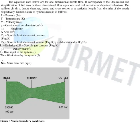
The equations used below are for one dimensional nozzle flow. It corresponds to the idealization and simplification of full two or three dimensional flow equations and real aero-thermochemical behaviour. The suffixes ch, th, x denote chamber, throat, and cross section at a particular length from the inlet of the nozzle respectively. Nomenclature of symbols used is as follows:
P – Pressure (Pa) T – Temperature (K) V – Velocity (m/s)
g– Gravitational acceleration (m/s2) [1] Height(m)
A Area (m2)
Cp – Specific heat at constant pressure (J/kg K)
Cv – Specific heat at constant volume (J/kg K) γ – Adiabatic index (Cp/Cv) I. – Enthalpy (J)R – Specific gas constant (J/kg K)
[1] – Density (kg/m3)
Q̇- Heat input to the system (J) W- – Work done by the system (J)
.
m
- Mass flow rate (kg/s)Figure 1Nozzle boundary conditions
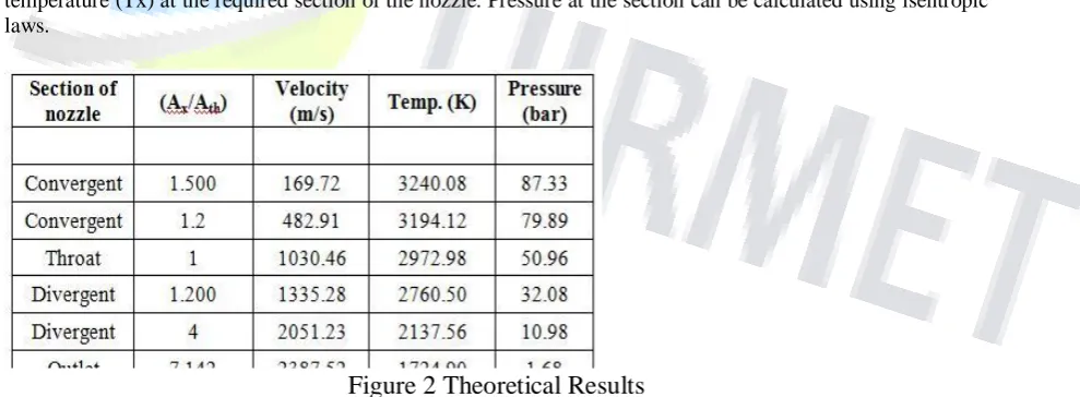
Figure 2 Theoretical Results
The continuity equation isx
AV
x x thA V
th th
The steady flow energy equation is as follows:
2 2
2 2
.
th xQ W V V
h gz h gz
m
1 1*
th x th x x thRT
T
A
A
T
V
(1) 2 2*
*
2
2
th x x thV
V
Cp T
Cp T
(2)Solving equation (1) and equation (2) simultaneously, we get the values of velocity (Vx) and temperature (Tx) at the required section of the nozzle. Pressure at the section can be calculated using isentropic laws.
III. COMPUTER SIMULATION OF NOZZLE
CFD is an engineering tool that assists experimentation. The following steps were performed in CFD of nozzle: Modelling, meshing, pre-processing, solution, post-processing
A. Modelling
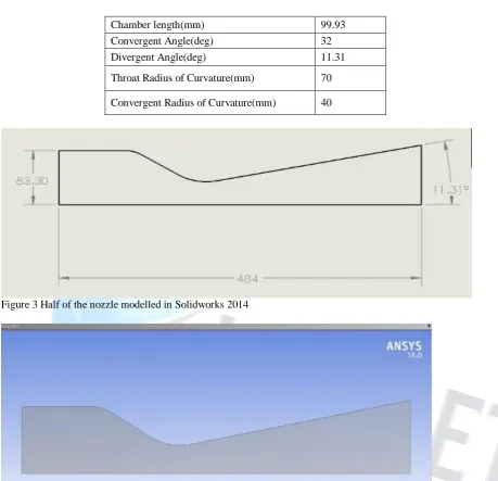
The 2-Dimensional modelling of the nozzle was done using Solidworks 2014 and file was saved in .stp format. The dimensions of the de Laval nozzle are presented in the table given below.
Table 1 Nozzle Dimensions
Parameter Dimension
Total Nozzle Length(mm) 484
Inlet Diameter(mm) 166.6
Throat Diameter(mm) 34.5
Chamber length(mm) 99.93
Convergent Angle(deg) 32
Divergent Angle(deg) 11.31
Throat Radius of Curvature(mm) 70
Convergent Radius of Curvature(mm) 40
Figure 3 Half of the nozzle modelled in Solidworks 2014
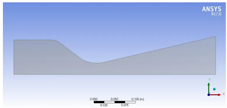
Figure 5 Axisymmetrically modelled nozzle section divergence angle changed to 130
Figure 6 Axisymmetrically modelled nozzle section divergence angle changed to 150 B. Meshing
Figure 7 Model meshed using high quality quad elements in Ansys Design Modeler
The shape the mesh is assigned to be very important when considering the solution accuracy and the solver stability. Hence there are two metrics to quantify or asses the condition of the mesh. They are (a) Orthogonal quality and (b) Skewness. Both metrics vary between 0 and 1. Orthogonal quality has to be maximum and Skewness has to be minimum.
The pick of mesh elements is so crucial that any distorted from ideal shapes if selected may lead to difficult in solving and less accurate results. The mesh element used in this model is of high quality one i.e. hex
mesh in 2D.
There are 5880 elements and the cell centres of these elements are taken into account for finding out the pressure and velocity fields. The average orthogonal quality is 0.982 and the average skewness value is 0.083. These values when seen as ideal have a values of 1 and 0 respectively.
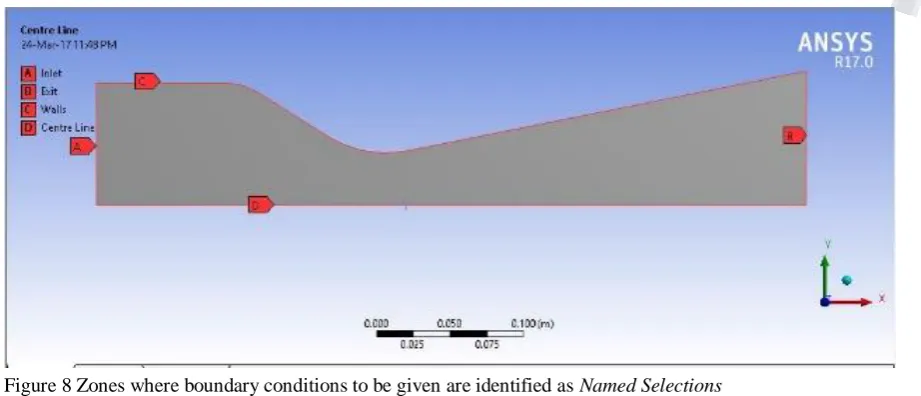
In order to complete the definition of domain we still need the boundary conditions. Boundary conditions are applied over the edges or boundaries in this case as shown below. Ansys needs proper identification of the boundaries or edges in the way of Named Selections.
Figure 8 Zones where boundary conditions to be given are identified as Named Selections
Pre-processing of the nozzle was done in ANSYS.FLUENT. 2-D and double precision settings were used while reading the mesh. The mesh was scaled since all dimensions were initially specified in mm. The mesh was checked in fluent and no critical errors were reported.
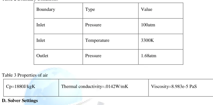
Table 2 Boundary Conditions
Boundary Type Value
Inlet Pressure 100atm
Inlet Temperature 3300K
Outlet Pressure 1.68atm
Table 3 Properties of air
Cp=1880J/kgK Thermal conductivity=.0142W/mK Viscosity=8.983e-5 PaS
D. Solver Settings
qThe solver selected to solve this problem is a density based solver. The dependence of time is turned off in the solver settings. Hence we do a steady state analysis. Compressible flows with Mach number greater than 3 are usually dealt with the density based solver. Mach number is presumed to be higher since the inlet and outlet pressure ranges are so enormous. The application of these nozzle pressures find place in rocket propulsion activities.
Table 4 Solver settings for running the simulation
`General Solver type- Density based 2D space : Axisymmetric
Models
Energy equation: On
Viscous model: Standard k-epsilon, realizable , enhanced wall treatment
Solution controls Courant number=5(Changes with 10 intervals)
Solution initialization Full Multi Grid(FMG)
Run Calculation Solution steering method is adopted
Iterations 5000
To include the effects of temperature in the governing equations, energy equation is turned on the turbulent eddy viscosity model used is standard k epsilon model, where k stands for turbulence kinetic energy and epsilon for the turbulent KE dissipation rate. Local mesh settings have been invoked to additionally smear high aspect ratio mesh cells on the geometry to capture the boundary layer turbulence phenomenon. That will only be calculated if the enhanced wall treatment is turned on. The only condition that exists for calculation of the wall effects is the height of the first cell adjacent to the wall should be very small. But too much small mesh cells near the boundary layer leads to convergence difficulties.
Figure 9 Inflation layers for capturing boundary layer effects
E. Residuals
Since the mathematical model (Governing equations+Boundary conditions) is discretely solved over the domain, two kinds of errors constitute, they are (1) Discretization error and (2) linearization error. The discretization error occurs when the domain is divided into a finite number of control volumes whereby only the cell center values are calculated. The continuous values are then computed after getting the pressure and velocity field values at the cell centers. This is done through advanced interpolation methods on the cells and their immediate neighbors. The distant the neighbors are the inaccurate the interpolated values become. Thus discretization errors are brought down by refining the mesh. But the value never becomes zero. Second error that is inevitable in the CFD simulation or other numerical method is the linearization error. Since the variables are nonlinear to find the root or the unknown function is bit hard. Thus these nonlinear equations are linearized using guess values and iterate them until the actual function is computed as a range between two values. This iteration can’t be run eternally. By stopping the chain of events requires inputting another value called the Residual or the tolerance limit. If the differences in values of two successive iterations fall below this residual value the loop ceases. Setting the residual is also challenging. In some cases if the residuals are input to be of very small order, difficulty in convergence occurs. Thus it has to be input by trial and error.
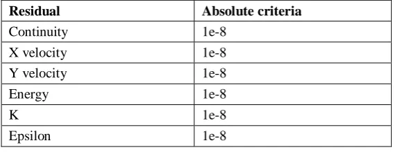
Table 5Convergence criteria
Residual Absolute criteria
Continuity 1e-8
X velocity 1e-8
Y velocity 1e-8
Energy 1e-8
K 1e-8
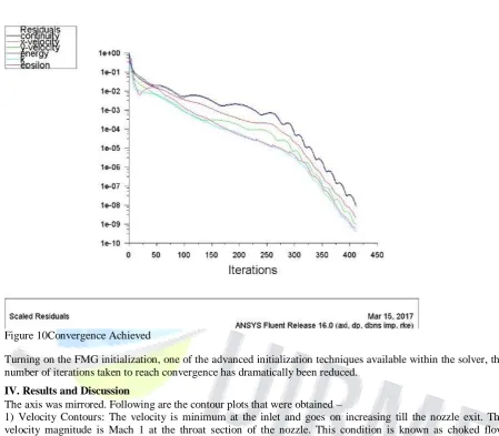
Figure 10Convergence Achieved
Turning on the FMG initialization, one of the advanced initialization techniques available within the solver, the number of iterations taken to reach convergence has dramatically been reduced.
IV. Results and Discussion
The axis was mirrored. Following are the contour plots that were obtained –
1) Velocity Contours: The velocity is minimum at the inlet and goes on increasing till the nozzle exit. The velocity magnitude is Mach 1 at the throat section of the nozzle. This condition is known as choked flow condition. The velocity at the nozzle exit is 2353.49 m/sec, which is around Mach 2.965.
Table 6 Variation of Mach number with changes in divergence angle Divergence Angle(0)
11.31 13 15
Mach Number
Figure 11 Variation of velocity along the nozzle.
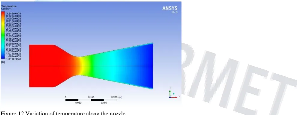
2) Temperature Contours: The temperature is maximum at the inlet and goes on decreasing till the outlet. The magnitude of temperature at the outlet is 1800 K.
Figure 12 Variation of temperature along the nozzle.
Figure 13 Variation of pressure along the nozzle
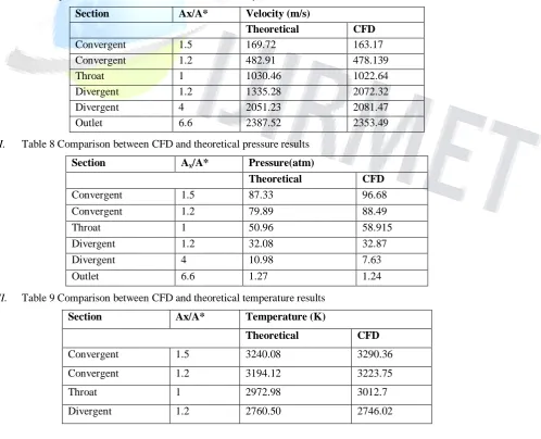
Table 7 Comparison between CFD and theoretical velocity results
Section Ax/A* Velocity (m/s)
Theoretical CFD
Convergent 1.5 169.72 163.17
Convergent 1.2 482.91 478.139
Throat 1 1030.46 1022.64
Divergent 1.2 1335.28 2072.32
Divergent 4 2051.23 2081.47
Outlet 6.6 2387.52 2353.49
I. Table 8 Comparison between CFD and theoretical pressure results
Section Ax/A* Pressure(atm)
Theoretical CFD
Convergent 1.5 87.33 96.68
Convergent 1.2 79.89 88.49
Throat 1 50.96 58.915
Divergent 1.2 32.08 32.87
Divergent 4 10.98 7.63
Outlet 6.6 1.27 1.24
II. Table 9 Comparison between CFD and theoretical temperature results
Section Ax/A* Temperature (K)
Theoretical CFD
Convergent 1.5 3240.08 3290.36
Convergent 1.2 3194.12 3223.75
Throat 1 2972.98 3012.7
Divergent 4 2137.56 2154.2
Outlet 6.6 1774.90 1800.5
Figure 14 Variation of Mach number with position (along the nozzle axis)
From the above Mach number vs Position plots, it is clear that as the divergence angle increases the shock formation (The drop in the velocity and rise in pressure is evident along the diverging part) seems to be reducing.[1]
V. Verification
According to Mach-Area ratio relation, Area ratio=6.6, Ratio of Sp. Heats =1.19
1 2 1 2 2 1.19 1 1.19 1 2 2 2
1 2 1
1
* 1 2
1 2 1.19 1
6.6 1
1.19 1 2
A M A M M M
Value computed from ANSYS FLUENT – M=2.965
1 2
1
1.19
1 1.19 1
1 1 2 1 1 2 100 56.64 1 1.19 1
1 1 2 2 throat exit inlet throat inlet throat P M P P P P P atm
Solving for Pexit,Pexit= 1.27 atm
Ansys Value= 1.24149 atm Hence verified analytically
VI. Conclusion
Following are the conclusion drawn from the analysis.
(1) With the increase of divergence angle the Mach number tends to rise and small shocks developed in the flow seem to be die out. This trend goes on with the increase of Mach number up to a limit, say beyond 20 deg of divergence angle, with still the area ratio kept constant, it has been observed that Mach number decreases very profoundly.
(2) Mass balance ensured that the simulation conforms to conservation of mass...
(3) CFD considers the factors like boundary layer effects, shock waves, radial velocity component and so on, which leads to some variance from theoretical results.
(4) The variation in the results of theoretical calculations and CFD are quite insignificant.
(5) It thus establishes the fact that one-dimensional simplified nozzle analysis is sufficient to predict the nozzle performance.
From the study conducted to assess the variation of divergence angle to the pressure, velocity and temperature It has been conclusively clear that as the divergence angle increases there’s a sudden rise in velocity and thus decrease in temperature and pressure. The simulation has been analytically verified using one dimensional isentropic flow equations. We also emphasize and acknowledge the need for an experimental validation to
accept our results in face value.
VII. References
1. Biju Kuttan P and M Sajesh, "Optimization of Divergent Angle of a Rocket Engine Nozzle Using Computational Fluid Dynamics", The International Journal Of Engineering And Science (IJES), Volume 2, No 2, 2013, pp 196-207.
2. International Journal of Mechanical And Production Engineering, ISSN: 2320-2092, Volume- 2, Issue- 4, April-2014 Theoretical & CFD Analysis Of De Laval Nozzle 33 THEORETICAL & CFD ANALYSIS OF DE LAVAL NOZZLE,1NIKHIL D. DESHPANDE, 2SUYASH S. VIDWANS, 3PRATIK R. MAHALE, 4RUTUJA S. JOSHI, 5K.R. JAGTAP , Department of Mechanical Engineering, Sinhgad Institute of Technology and Science, Pune, India
4. Varun, R.; Sundararajan,T.; Usha,R.; Srinivasan,k.; Interaction between particle-laden under expanded twin supersonic jets, Proceedings of the Institution of Mechanical Engineers, Part G: Journal of Aerospace Engineering 2010 224: 1005.
5. Pandey,K.M.; Singh, A.P.; CFD Analysis of Conical Nozzle for Mach 3 at Various Angles of Divergence with Fluent Software, International Journal of Chemical Engineering and Applications, Vol. 1, No. 2, August 2010, ISSN: 2010-0221.
6. Natta, Pardhasaradhi.; Kumar, V.Ranjith.; Rao, Dr. Y.V. Hanumantha.; Flow Analysis of Rocket Nozzle Using Computational Fluid Dynamics (Cfd), International Journal of Engineering Research and Applications (IJERA), ISSN: 2248-9622,Vol. 2, Issue 5, September- October 2012, pp.1226-1235.
7. K.M. Pandey, Member IACSIT and A.P. Singh. K.M.Pandey, Member, IACSIT and S.K.YadavK.M.Pandey and S.K.Yadav, ―CFD Analysis of a Rocket Nozzle with Two Inlets at Mach2.1, Journal of Environmental Research and Development, Vol 5, No 2, 2010, pp- 308-321.
8. Shigeru Aso, ArifNur Hakim, Shingo Miyamoto, Kei Inoue and Yasuhiro Tani “ Fundamental study of supersonic combustion in pure air flow with use of shock tunnel” Department of Aeronautics and Astronautics, Kyushu University, Japan , Acta Astronautica 57 (2005) 384 – 389.
9. P. Padmanathan, Dr. S. Vaidyanathan, Computational Analysis of Shockwave in Convergent Divergent Nozzle, International Journal of Engineering Research and Applications (IJERA), ISSN: 2248-9622 ,Vol. 2, Issue 2,Mar-Apr 2012, pp.1597-1605.