All rights reserved by www.ijirst.org 44
Performance Based Seismic Analysis of a Building
with Soft Storey
Prof. Rekha Shinde Prof. Mukesh Shinde
Professor Professor
Department of Civil Engineering Department of Mechanical Engineering
M.I.T. Ujjain (M.P.) M.I.T. Ujjain (M.P.)
Abstract
“performance-based” seismic design, which can be thought of as an explicit design for multiple limit states Analyzing structures for various levels of earthquake intensity and checking some local and/or global criteria for each level has been a popular academic exercise for the last couple of decades, but the crucial development that occurred relatively recently was the recognition of the necessity for such procedures by a number of practicing engineers influential in code drafting. The main cause of failure of multi-storey multi-bay reinforced concrete frames during seismic motion is the soft multi-storey sway mechanism or column sway mechanism. The seismic inertia forces generated at its floor levels are transferred through the various beams and columns to the ground. The failure of a column can affect the stability of the whole building, but the failure of a beam causes localized effect.The main objective of this search work is to present a detailed 3 dimensional seismic analysis and capacity based design of G+3, G+8 & G+15 storied-three bay reinforced concrete frame. The report provides an introduction to the earthquake, effects, designing of the buildings and studies review of literature pertaining to performance based seismic analysis. It highlights various aspects related to the capacity based designing and explains about Limit State design which an old method of building designing. The study reveals modeling and analysis. The capacity based design of G+3; G+8 & G+15 of old and new building design methods have been modeled and analyzed. The report draws out the result of study and provides a comparative study. The project report also provides a comprehensive conclusion and offers a scope for future research as well.
Keywords: Performance-Based Design, limit State Design, Reinforced Concrete Buildings, Capacity Based Analysis, 3D Effects.
___________________________________________________________________________________________________________
I.
I
NTRODUCTIONCivil engineering structures are mainly designed to resist static loads. Generally the effects of dynamic loads acting on the structure are not considered. This feature of neglecting the dynamic forces sometimes becomes the cause of disaster, particularly in case of earthquake. The resent example of this category is Bhuj earthquake occurred on Jan.26, 2001. This has created a growing interest and need for earthquake resistant design of structures.
Conventional Civil Engineering structures are designed on the basis of strength and stiffness criteria. The strength is related to ultimate limit state, which assures that the forces developed in the structure remain in elastic range. The stiffness is related to serviceability limit state which assures that the structural displacements remains within the permissible limits. In case of earthquake forces the demand is for ductility. Ductility is an essential attribute of a structure that must respond to strong ground motions. Ductility is the ability of the structure to undergo distortion or deformation without damage or failure which results in dissipation of energy. Larger is the capacity of the structure to deform plastically without collapse, more is the resulting ductility and the energy dissipation. This causes reduction in effective earthquake forces.
The seismic inertia forces generated at its floor levels are transferred through the various beams and columns to the ground. The correct building components need to be made ductile. The failure of a column can affect the stability of the whole building, but the failure of a beam causes localized effect. Therefore, it is better to make beams to be the ductile weak links than columns. This method of designing RC buildings is called the strong-column weak-beam design method.
Most of the energy developed during earthquake is dissipated by columns of the soft stories. In this process the plastic hinges are formed at the ends of columns, which transform the soft storey into a mechanism. In such case the collapse is unavoidable. Therefore, the soft stories deserve a special consideration in analysis and design.
All rights reserved by www.ijirst.org 45 In multi-storey reinforced concrete building this can be achieved by formation of plastic hinges at the regions of nearly all the beams in all stories of the building while vertical members (column and walls) remain essentially elastic in all stories, with the exception of the base of the bottom storey. This will provide a strong column-weak beam structure by eliminating the possibility of column sway mechanism (soft storey) of building and avoiding shear failures in columns and beams. This project will illustrate t he capacity design procedure for multi- storey building frame.
II.
M
ODELING AND ANALYSIS BY CAPACITY BASED DESIGNThe overall capacity of a structure depends on the strength and deformation capacity of the individual components of the structure. In order to determine capacities beyond the elastic limits, some form of nonlinear analysis, such as the pushover procedure, is required. This procedure uses a series of sequential elastic analysis, superimposed to approximate a force displacement capacity diagram of the overall structure. A lateral force distribution is again applied until additional components yield. This process is continued until the structure become unstable or until a predetermined limit is reached. Using the following loading data, analysis of the frame is carried out with all the load combinations as per IS 1893(Part 1):2002. The maximum moments and forces for the beams and columns for all the load combinations for each member are considered for the design. The different load combinations are:
(1) 1.5(DL+IL) (2) 1.2(DL+IL+EL) (3) 1.2(DL+IL-EL) (4) 1.5(DL+EL) (5) 1.5(DL-EL) (6) 0.9DL+1.5EL (7) 0.9DL-1.5EL
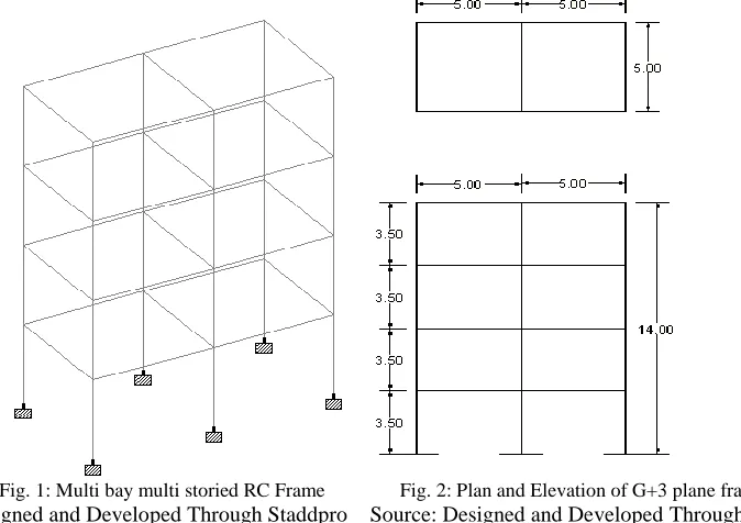
Floor plan of a building is given. The plan is regular and has all columns equally placed. The building space frame is divided into a number of frames. An frame is considered for the analysis and design. A four storeyed( G+3) reinforced concrete plane frame, as shown in fig, has been designed on the concept of capacity based.
Fig. 1: Multi bay multi storied RC Frame Fig. 2: Plan and Elevation of G+3 plane frame
Source: Designed and Developed Through Staddpro Source: Designed and Developed Through Auto CAD
III.
C
OMPARATIVE STUDY OF CAPACITY BASED DESIGN AND LIMIT STATE DESIGN ONG+3,
G+8
&
G+15
FRAME AND RESULT
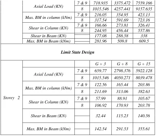
Capacity Based Design
All rights reserved by www.ijirst.org 46 Axial Load (KN) 7 & 9 718.935 3375.472 7559.166
8 1015.546 4257.441 9157.635
Max. BM in column (kNm) 7 & 9 216.05 354.95 423.13 8 317.54 591.69 723.16
Shear in Column (KN) 7 & 9 166.66 273.81 326.41 8 244.95 456.44 557.86 Shear in Beam (KN) 177.08 288.58 338 Max. BM in Beam (kNm) 281.96 509.8 609.5
Limit State Design
Storey 2
G + 3 G + 8 G + 15
Axial Load (KN) 7 & 9 659.77 2798.376 5922.128 8 1015.546 4050.271 8039.478
Max. BM in column (kNm) 7 & 9 122.56 165.44 203.86 8 211.69 313.06 382.63
Shear in Column (KN) 7 & 9 57.99 88.91 105.67 8 106.92 170.93 203.78
Shear in Beam (KN) 32.44 115.23 140.56
Max. BM in Beam (kNm) 142.54 291.53 355.61
IV.
C
OMPARATIVE RESULT OF CAPACITY BASED DESIGN AND LIMIT STATE DESIGN ONG+3,
G+8
&
G+15
FRAME HAS BEEN SHOWN BELOW WITH THE HELP OF BAR CHART
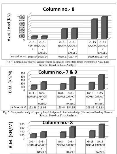
All rights reserved by www.ijirst.com 47 Fig. 4.Comparative study of capacity based design and Limit state design (Normal) on Axial Load
Source: Based on Data Analysis
Fig. 5.Comparative study of capacity based design and Limit state design (Normal) on Bending Moment Source: Based on Data Analysis
Fig. 6.Comparative study of capacity based design and Limit state design (Normal) on Bending Moment Source: Based on Data Analysis
0 100 200 300 400 500
G+3 -NORMAL
G+3 -CAPACIT
Y BASSED
G+8 -NORM.
G+8 -CAPACIT
Y BASSED
G+15 NORM.
G+15 CAPACIT
Y BASSED
Max.- B.M. 122.56 216.05 165.44 354.95 203.86 423.13
B.
M
.
(KN
/M
)
Column no.- 7 & 9
0 200 400 600 800
G+3 -NORMAL
G+3 -CAPACIT
Y BASSED
G+8 -NORM.
G+8 -CAPACIT
Y BASSED
G+15 NORM.
G+15 CAPACIT
Y BASSED
Max.- B.M. 211.69 317.54 313.06 591.69 382.63 729.16
B.
M.
(KN/M
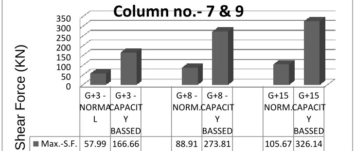
All rights reserved by www.ijirst.com 48 Fig. 7.Comparative study of capacity based design and Limit state design (Normal) on Shear Force.
Source: Based on Data Analysis
Fig. 8.Comparative study of capacity based design and Limit state design (Normal) on Shear Force. Source: Based on Data Analysis
Fig. 9.Comparative study of capacity based design and Limit state design (Normal) on Bending Moment in Beam Source: Based on Data Analysis
Fig. 10.Comparative study of capacity based design and Limit state design (Normal) on Shear Force in Beam. Source: Based on Data Analysis
0 50 100 150 200 250 300 350 G+3 -NORMA L G+3 -CAPACIT Y BASSED G+8 -NORM. G+8 -CAPACIT Y BASSED G+15 NORM. G+15 CAPACIT Y BASSED
Max.-S.F. 57.99 166.66 88.91 273.81 105.67 326.14
Shear
F
orc
e
(KN
)
Column no.- 7 & 9
0 100 200 300 400 500 600 G+3 -NORMA L G+3 -CAPACIT Y BASSED G+8 -NORM. G+8 -CAPACIT Y BASSED G+15 NORM. G+15 CAPACIT Y BASSED
Max.-S.F. 106.92 244.95 170.93 456.44 203.78 557.86
S
h
e
a
r Fo
rce
(KN)
Column no.- 8
0 100 200 300 400 500 600 G+3 -NORMA L G+3 -CAPACI TY BASSED G+8 -NORM. G+8 -CAPACI TY BASSED G+15 NORM. G+15 CAPACI TY BASSED
Max.- B.M. 139.57 279.66 291.53 492.27 355.61 582.38
B.
M.
(KN/M
)
Beam
0 50 100 150 200 250 300 350 G+3 -NORMA L G+3 -CAPACI TY BASSED G+8 -NORM. G+8 -CAPACI TY BASSED G+15 NORM. G+15 CAPACI TY BASSED
Max.-S.F. 56.42 177.08 115.22 288.58 140.56 338.43
All rights reserved by www.ijirst.com 49
V.
C
ONCLUSION(1) Capacity based earthquake resistant design is futuristic approach to design of reinforced concrete structures especially for multi-bay multi storied reinforced concrete buildings.
(2) This concept is to restrict the formation of plastic hinges in the beams only hence collapse occurs through the beam mechanism only, which localize the failure and hence leads to less destruction and loss of lives.
(3) Collapse due to sway mechanism can cause failure of a storey or whole frame. As its approach is to eliminate sway mechanism by making columns stronger than beams, this method is very effective in design of soft-storey frames. (4) This method also eliminates the possibility of shear mode of failure (which is brittle by nature hence failure occurs
suddenly) by making shear capacity of elements more than their moment capacity.
(5) Compared with the conventional design methods for earthquake resisting structures although this method is little costlier but is more effective in resisting the earthquake forces.
(6) This method of design is more realistic because the calculations are based on provided reinforcement and the over strength of the structure which takes into account the reserve strength beyond elastic limit.
(7) As the building can be reused after minimal repairment after occurrence of earthquake hence this method of design should be adopted for public utility buildings like schools, colleges, hospitals etc.
(8) Multilevel seismic hazards are considered with an emphasis on the transparency of performance objectives. (9) Building performance is guaranteed through limited inelastic deformation in addition to strength and ductility. (10)Seismic design is oriented by performance objectives interpreted by engineering parameters as performance criteria. (11)An analytical method through which the structural behavior, particularly the nonlinear behavior is rationally obtained. (12)The building will meet the prescribed performance objectives reliably with accepted confidence & the design will
ensure the minimum lifecycle cost.
Thus, it is observed that more research work is needed especially for development of PBED method for various other different types of structures. It is important to note that in the PBED method, control of drift and yielding is built into the design process from the very start, eliminating or minimizing the need for lengthy iterations to arrive at the final design. Other advantages include the fact that innovative structural schemes can be developed by selecting suitable yielding members and/or devices and placing them at strategic locations, while the designated non-yielding members can be detailed for no or minimum ductility capacity. All of these would translate into enhanced performance, safety and economy in lifecycle costs. As the PBED accepts damage in seismic events, and proves to be the most economical solution, and the performance can be quantified and confirmed to the owner„s desires, it is quite possible that it can be misused by the owner for personal profits.
R
EFERENCES1. Agarwal Pankaj and Shrikhande Manish, “Earthquake resistant design of structures”, Prentice Hall of India Private Limited
2. Andre Filiatrault, Ioannis P. Christovasilis, Assawin Wanitkorkul, John W. van de Lindt(2010), “Experimental Seismic Response of a Full-Scale Light-Frame Wood Building “Journal of Structural Engineering-asce - J struct eng-asce , vol. 136, no. 3
3. Bruce R. Ellingwood, Earthquake risk assessment of building structures Reliability Engineering & System Safety Volume 74, Issue 3, December 2001, Pages 251–262
4. Filiatrault, A. and Folz, B. (2002), “Performance-Based Seismic Design of Wood Framed Buildings”, ASCE Journal of Structural Engineering, Vol. 128, No. 1.
5. I.S. 1893, “Criteria for Earthquake Resistant Design of Structures (part 1) General Provisions and Buildings (Fifth Revision)”, Bureau of Indian Standards, 2002.
6. I.S.456, “Plain and Reinforced Concrete - Code of Practice”, Bureau of Indian Standards, 2000.
7. I.S 13920, “Ductile Detailing of Reinforced Concrete Structures Subjected to Seismic Forces-Code of Practice”, Bureau of Indian Standards, 1993.
8. IS 875 (Part III for wind load design).
9. Jack W. Baker and c. Allin Cornell (2006), “Spectral shape, epsilon and record selection”, earthquake engineering and structural dynamics earthquake eng. struct. dyn. 2006; 35:1077–1095 published online 12 April 2006 in wiley interscience.
10. K Rama Raju, ACinitha and Nagesh R Iyer (2012), “Seismic performance evaluation of existing RC buildings designed as per past codes of practice”, Sadhana¯ Vol. 37, Part 2.
11. M.C. Kunde &R.S. Jangid, “Seismic behavior of isolated bridges: A-state-of-the-art review, Electronic Journal of Structural Engineering, 3 (2003)
12. M.J.N. Priestley, G.M. Calvi, M.J. Kowalsky (2007) Displacement – Based Seismic Design of Structures. IUSS Press, Pavia, Italy
All rights reserved by www.ijirst.com 50 14. Prabuddha Dasgupta, Subhash C. Goel, Gustavo Parra-montesinos, and K. C. Tsai (2004), Performance based Seismic design and behavior of Composite Buckling Restrained Braced Frame, 13th World Conference on Earthquake Engineering, Vancouver, B.C., Canada, August 1-6, 2004.
15. S.R. Satish Kumar and G Venkateswarlu (2008), Performance Based Design of Reinforced Concrete Plane Frames, The 14th world Conference on Earthquake Engineering, Oct., 2008, Beijing, China.
16. SP 16, “Design Aids for Reinforced Concrete”, Bureau of Indian Standards, 1980.
17. Serafim Arzoumanidis Ayman Shama,& Farhang Ostadan (2005), “Performance-based seismic analysis and design of suspension bridges, Earthquake Engineering & Structural Dynamics, Special Issue: Special Issue on Earthquake Engineering for Transportation Structures Volume 34, Issue 4-5, John Wiley & Sons, Ltd.
18. S. Pei, J. W. van de Lindt (2009), “Methodology for earthquake-induced loss estimation: An application to woodframe buildings” Structural Safety - struct saf , vol. 31, no. 1