1. INTRODUCTION
An important fuel saving element in hybrid electric vehicles (HEV) is the regenerative braking system (RBS), saving a considerable amount of energy during the brake of a vehicle [1]. The total energy dissipated through braking during a typical urban area drive may reach up to 34% of the total traction energy. In large cities, with frequent stops and lots of intersections, this portion may reach up to 80% [2]. During brake phase, the electric traction motor of an electric or hybrid electric vehicle can be easily controlled to function as a generator, converting some of the kinetic energy of the vehicle into electric energy. The recovered energy can be stored in an electric energy storage system and subsequently used for the propulsion, significantly reducing the vehicle's overall energy consumption and exhaust emissions [3]. Accordingly, a well-designed RBS can increase the driving range of a HEV up to 16% [4], and enhance the safety of HEV [5]. Nevertheless, a relatively limited research has focused on the brake system for HEVs compared to powertrain technology development [6].
One advanced feature in braking system of modern vehicles is the anti-lock brake system (ABS). Locking up of front and rear wheels can cause loss of vehicle stability and an increase in stopping distance. When a
wheel lock up is detected, the braking control system reduces the pressure applied to the brake actuators and brings the wheel back to spinning. In conventional vehicles, ABS is generally achieved through the control of hydraulic or pneumatic pressure which is fed to the wheel brake actuators.
In electric vehicles and series HEVs, where electric motor (EM) is the only source of traction of vehicle, ABS can be achieved through controlling the EM due to its desirable response time, which is faster than the response time of mechanical systems [7]. Implementation of mechanical ABS (i.e. ABS through the mechanical actuators) as the primary braking system along RBS in HEVs would greatly increase the complexity of braking system and also the manufacturing cost of electric vehicles. In addition, by the activation of mechanical ABS, the regenerative brake system as the secondary braking system in HEVs is typically inactivated which substantially decreases the amount of recovered energy. Combined use of anti-lock and regenerative braking systems in HEVs can greatly reduce these complexities and has been the focus of few recent studies [8-11]. Gao and Ehsani [8] have proposed a controller for EM by combining ABS and RBS functions. In their study, they assumed that the vehicle speed and road surface conditions are known parameters during braking. These assumptions are not realistic and dramatically
Design of an Anti-Lock Regenerative Braking System for a
Series Hybrid Electric Vehicle
M. M. Tehrani1,*, M. R. Hairi -Yazdi1, B. Haghpanah-Jahromi2, V. Esfahanian1, M. Amiri1and A. R. Jafari1
1 Mechanical Engineering Department, University of Tehran, Tehran, Iran
2 Mechanical & Industrial Engineering Department, Northeastern University, Boston, Massachusetts, USA
* Email: masih@ut.ac.ir
Abstract
In this paper, an adaptive rule based controller for an anti-lock regenerative braking system (ARBS) of a series hybrid electric bus (SHEB) has been proposed. The proposed controller integrates the regenerative braking and wheel lock functions by controlling the electric motor of the hybrid vehicle, without using any conventional mechanical anti-lock braking system. The performance of the proposed system is evaluated by a comprehensive vehicle dynamics model in MATLAB/Simulink. Using the designed ARBS, the braking and regenerative performances of SHEB have significantly improved in slippery roads while the slip ratios are kept between 0.15 and 0.20.
Keywords: Anti-Lock Regenerative Braking System, Series Hybrid Electric Vehicle, Slip Control, Adaptive Rule Based Controller
compromise the performance of braking system in different road conditions. Mutoh et.al [9] studied the safety of EVs during driving and braking of special EVs with the front and rear wheel independent driving capability. They showed that electric braking control system can prevent vehicles from experiencing wheel lock and can improve the riding comfort regardless of driver’s brake pedal application. Recently, an implementation of ABS for the parallel hybrid electric vehicle with combining anti-lock regenerative braking system and anti-lock hydraulic braking system was proposed [10-11].
The prediction of wheel lock up is of great importance in the design of ABS. In industrial ABSs, the angular velocities of the wheels are measured with sensors and are directly utilized to determine the risk and prevent the wheel locked-up before it happens [12]. In some recent studies, the slip ratios of the wheels have been estimated from the data from wheel angular velocity sensor and utilized in ABS controller [13-14]. In these systems, ABS is aimed to control the wheel slip at an optimum value that can provide maximum traction force during heavy braking [15]. The proposed controller utilizes wheels slip ratios for predicting the wheel lock up situation. In order to calculate the wheel slip ratio, the absolute velocity of the vehicle other than the linear speeds of wheels during braking, is needed. The absolute vehicle speed during braking is estimated from the angular speed of the wheels and the amount of braking torque.
In this paper, a controlling scheme of an anti-lock regenerative braking system (ARBS) for a SHEB has been proposed. The proposed system utilizes the inborn advantage of the electric vehicle by controlling the braking torque applied to the wheels through the EM, which operates as an electric generator during braking. This system can handle the vehicle instability and steerability issues on slippery roads without utilizing additional conventional costly hardware such as hydraulics or pneumatics ABS apparatus. The proposed system contains a speed observer module that can estimate the absolute velocity of the vehicle during braking from the values of applied braking torque and acceleration of the wheels. The data from this module is used to restrict the slip ratio of the wheels between 0.15 and 0.20. The ARBS has been shown to effectively improve the braking performance and fuel consumption of SHEB in different road conditions.
Abbreviation
ABS Anti-lock brake system
ARBS Anti-lock regenerative braking system
EM Electric motor
HEV Hybrid electric vehicles
RBS Regenerative braking system
SHEB Series hybrid electric bus
SoC State of Charge of the battery
Nomenclature
b Cycle number of ABS process
F Braking force
g Acceleration of gravity
h Center of gravity height
J Wheel moment of inertia
La Distances of the center of gravity from front
axle
Lb Distances of the center of gravity from rear
axle
M Mass of the vehicle
N Normal force of the wheel
R Radius of the wheel
S Slip ratio
S* Critical slip ratio
T Braking torque
Tdem Braking torque demand
Tmechbrake Mechanical braking torque
Treg Regenerative braking torque
Treg. Prev. Last value of regenerative braking torque during ABS
TT Total braking torque
V Vehicle speed
Vmin A limit value of vehicle speed for
deactivation of ABS
(S) Adhesive coefficient between the road and the wheel
p Peak value of adhesive coefficient
s Sliding value of adhesive coefficient
Angular speed of the wheel
f Index of front wheels
r Index of rear wheels
2. MODELING
To evaluate the performance of the proposed braking system, a comprehensive model of a series hybrid electric bus (SHEB) is constructed in
Ȧ
µ
µ
µ
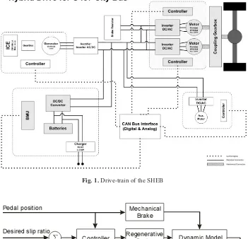
MATLAB/Simulink. Figure 1, shows the schematic map of hybrid drive-train of the SHEB, where RBS components are shaded in dark color. The brake simulation module includes five main blocks of vehicle and tire dynamics, EM dynamics, mechanical brake system, ARBS controller and speed observer as shown in Figure 2.
2. 1. Vehicle and Tire Dynamics
The block of vehicle and tire dynamics includes vehicle dynamics relations, tire dynamics relations and road condition. Figure 3 shows a two wheel model of HEV for braking studies, where the wind force, hill
climbing force and rolling resistance are neglected. In
this figure, Ffand Frare the braking forces acted on
front and rear wheels, respectively. M is the mass of
the vehicle and g is acceleration of gravity. La, Lband
hare distances of the center of gravity from front axle,
rear axle and center of gravity height, respectively.
The slip ratio, S, is defined as the relative difference
between the vehicle speed and the linear wheel speed:
(1)
where V is the vehicle speed, is the angular
speed of the wheel and R is the radius of the wheel. The traction forces, or braking forces in case of
Ȧ
V R V
S Z
Fig. 1.Drive-train of the SHEB
Controller Dynamic Model
Speed Observer Desired slip ratio
Observed slip ratio Pedal position
+
-
Mechanical Brake
Regenerative Brake
Fig. 2.Comprehensive dynamics model
braking, shown in Figure 3 can be expressed as:
(2)
where (S) is the adhesive coefficient between the
road surface and the tire which is a function of slip
ratio, S. Also, Nis the normal force of the tire (fand r
indices point to front and rear tires).
Neglecting wind force, rolling resistance, and hill climbing force, the equation of the vehicle motion can be expressed as:
(3)
The equation of the wheel motion can be expressed as:
(4)
where Jwis the wheel moment of inertia and Tmis
the total braking torque.
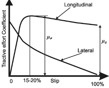
The braking force is a function of the adhesive coefficient between the tire and the roadway and is determined by the road surface condition and the slip ratio. The typical variation of road adhesive coefficients versus the wheel slip ratio is shown in Figure 4, [2]. The adhesive coefficient reaches its peak
value ( p) near the critical slip ratio of S*for most
road conditions. When the slip ratio is below S*,
increasing the slip ratio can enhance the traction force.
Once the slip ratio exceeds S*, the traction force will
decrease as a result of the decrease in adhesive
coefficients down to the sliding value ( s).
The adhesive coefficient in the lateral direction, a key factor in the stability and the steerability of vehicle, increases by decreasing the slip ratio. Therefore, confining the slip ratio under the critical
slip ratio of S* guarantees the stability and the
steerability of vehicle.
2. 2. Electric Motor Dynamics
The block of EM Dynamics includes the EM, which functions as generator during braking, batteries and brake resistor. EM is coupled to the rear wheels by drive train. Figure 5 schematically illustrates the regenerative braking system components. The pneumatic system is not shown in this figure.
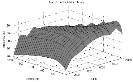
Generator and traction performances of electric motor are almost identical. The maximum torque and power of EM is a function of the speed of EM as shown in Figure 6. In the vehicle under study, there are two coupled electric traction motors. The generator’s efficiency is defined as the ratio of output electric power to input mechanical power. Efficiency map of
µ
µ
RF T dt d
Jw
Z
m) (Ff Fr dt
dV
M
µ
r r r r
f f f f
N S F
N S F
u u
P P
Fig. 4.Road adhesive coefficients
Fig. 3.Two wheel model of vehicle
the generator is almost equal to efficiency map of EM in traction and is shown in Figure 7.
During braking, not only does locking of wheels contribute to the increase of stopping distance, but it also lowers the amount of recovered energy. That is because in case of locking wheels, the rotational speed of connected EM becomes close to zero and the maximum amount of generator power of EM decreases according to Figure 6.
Regenerated energy by EM is given to the batteries. Batteries store a portion of this energy according to their limitations and free capacity, and the additional energy is dissipated in brake resistor. The batteries that are utilized in the bus under study are 40 Ah lithium-polymer batteries. This series of batteries consists of 168×3.7V battery cells. The internal resistance of each battery cell is approximately 2 mÙ. Changes in charge of batteries due to the absorbed energy by generator
are expressed by the percentage of the State of Charge (SoC).
Through the block of EM dynamics, the amount of absorbed energy in batteries, subsequent changes in SoC and the amount of energy which is dissipated in Fig. 6.Maximum EM braking torque and power in various shaft speeds
Fig. 7.Map of EM efficiency Fig. 5.Regenerative braking system components
the brake resistor are determined.
2. 3. Mechanical Brake System
Mechanical braking system of the SHEB under study is a pneumatic braking system. Pneumatic braking pressure which acts both on front and rear wheels is a function of brake pedal displacement, as shown in Figure 8. Total braking torque of rear wheels is the sum of generator braking torque that is provided by EM and the mechanical (pneumatic) braking torque. The pneumatic braking torque is determined by the pneumatic braking pressure and specifications of the wheel braking actuators.
The mechanical brake system of SHEB is only controlled by brake pedal displacement applied by the driver. There is no additional system (such as ABS) to generate dynamics commands to affect the mechanical brake forces. Therefore, if the angular displacement of brake pedal is constant in a test cycle, the pneumatic brake pressure and force are constant.
3. BRAKE CONTROLLER
The inputs of controller unit are front and rear wheels slip ratios and brake pedal displacement. The brake control strategy, defined in the brake controller module, determines the regenerative torque that is applied to the rear wheel during braking.
In brake pedal angles below six degrees (mechanical brake is inactive according to Figure 8), the controller increases regenerative braking torque linearly with brake pedal angle to simulate the retarder function in conventional city bus. The retarder acts similar as an engine brake in conventional heavy-duty vehicles. The controller applies available regenerative braking force (maximum braking force produced by the electric motor) when mechanical brake is activated in brake pedal angle of six degrees. This is very similar to “the series braking system with optimal energy recovery” [2].
If the wheels are predicted to lock up by controller, the controller reduces and controls the regenerative braking torque allowing the wheels to reach their optimum slip ratio. To predict rear wheel locking up and to find semi-optimal braking torques, slip ratios are considered. If the slip ratio of rear (driven) wheel is below 0.18 the driver desired braking torque is applied to the wheels, if the slip ratio of the rear wheels exceeds 0.18 the brake controller decreases the EM braking torque to let the wheels accelerate. When lock up risk has removed, the braking torque is reapplied, lower than the previous amount that had led to wheel lock up. By this procedure, the semi-optimal braking torque associated with the near optimum slip ratio of 15-20% is determined in a few steps. If all the regenerative braking torque is removed and wheel is still in lock mode, EM may change its state from Fig. 8.Pneumatic braking pressure versus brake pedal displacement
generator to traction motor to overcome mechanical braking torque, letting the wheel to accelerate.
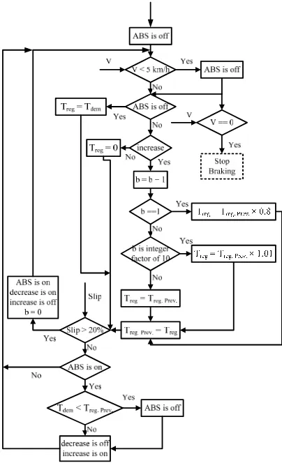
The decision algorithm of developed adaptive rule based brake controller is illustrated in Figure 9.
As shown in Figure 9, these main rules are effective in the decision making algorithm of developed brake controller.
• If the vehicle speed (V) is zero, the brake
process will be halted.
• If the vehicle speed (V) is less than 5 km/h
(Vmin), ABS is deactivated.
• If the ABS is deactivated, regenerative brake
torque (Treg) will be equal to the brake torque
demand (Tdem) which is specified by brake
pedal.
• The last value of regenerative braking torque
during ABS process will be stored in Treg. Prev.
• In the first cycle that ABS is activated and the
“increase” is on, regenerative braking torque
will be 20% less than Treg. Prev. . In the other
cycles, if cycle number (b) is an integer factor
of 10, Tregwill be 1% greater than Treg. Prev. . In
the other cases, Tregwill be equal to Treg. Prev..
• If the slip ratio of rear wheel is greater than
20%, ABS is activated, the “decrease” is turned on, the “increase” is shut off, and cycle number of ABS process (b) is restored to zero.
• If the slip ratio of rear wheel is not greater than
20% and ABS is activated, the brake torque
demand (Tdem) is compared to Treg. Prev. . If Tdem
is greater, the “decrease” is turned off and the “increase” is turned on. Otherwise, ABS is deactivated.
There are two adaptive modes to detect the road surface condition in the decision algorithm of developed brake controller. If the regenerative braking torque is greater than adhesive capacity of road surface (the slip ratio is greater than 20%), the new regenerative braking torque is 20% less than the previous one (the “decrease” mode). If the regenerative braking torque is less than adhesive capacity of road surface (the slip ratio is not greater than 20%) and Treg. Prev. is less than demand torque
(Tdem), the regenerative braking torque becomes 1%
greater than the previous one in every 10thcycles of
ABS (the “increase” mode).
These two adaptive modes of developed brake controller can detect the static or the dynamics condition of adhesive capacity of road surface. In the result section, the results from some performance tests are presented to show the capability of these adaptive modes.
4. SPEED OBSERVER
The proposed speed observer unit is designed to calculate the absolute velocity of the vehicle from the values of applied torque to wheels and wheels acceleration. To compute the vehicle’s absolute velocity, the deceleration of vehicle is calculated by the derived vehicle dynamic formulas and then integrated.
First consider the situation where neither the front
wheels nor the rear wheels are locked ( f >0 and r >0).
From relation (4), the total braking torque acting on vehicle is [2]:
(5)
Therefore, the deceleration of vehicle becomes: f
f f r r r f
r F J T J T
F
R( ) Z Z
Ȧ Ȧ
Fig. 9. Flow Chart of Developed Brake Controller
(6)
Assuming that the vehicle initial absolute speed and
initial rear and front wheels linear speeds are V0, V0r
and V0f, respectively, the absolute vehicle velocity can
be obtained by integration as:
(7)
where TT is the total braking torque of front and
rear wheels.
In this case, the adhesion coefficients of front and rear wheels can be calculated as:
(8)
(9)
Now, consider the situation where only rear wheels
are locked ( ). It can be shown that the braking
force acting on rear wheels is obtained by [2]:
(10)
where . Thus, the net braking force acting on
vehicle is:
(11)
The vehicle deceleration can be calculated from relation (3). By integrating the vehicle deceleration over time, assuming that the initial value of absolute vehicle speed and initial front wheels speed at the beginning of this situation are V0 and V0f, the vehicle absolute velocity can be obtained as:
(12)
For the situation where only front wheels are locked, in a similar way the vehicle absolute velocity is obtained as:
(13)
» » ¼ º « « ¬ ª³
MR dt T V V MR J r r r r . 0 2 « « ¬ ª³
h L L gdt h L L V V f f b f0 P P
P
»» ¼ º « « ¬ ª³
MR dt T V V MR J f f f f . 0 2³
h L L gdt h L L V V r r a r 0 P P P » ¼ º « ¬ ª R T R J h L L h L MgL FF f f f
r r
a r f
r P P Z
P ) ( Mg F h L h L Mg
F a f
r r r P P 0 r Z
L h V gMg LR J T N F g a r r r r r r u u Z P
L h V gMg LR J T N F g a r r r r r r u u Z P
r r f
f fr V V
MR J V V MR J V
V 0 2 0 2 0
MR dt TT
³
. RM T T J J dtdV rZr fZf r f
Read: V0, V0rand V0f
Read: Vrand Vf
Vr== 0
Vf== 0 Vf== 0
Yes No Both Locked: Eq. (16) Yes Rear Locked: Eq. (13) No Front Locked: Eq. (14) No locking: Eq. (8) Yes No Read: Treg, Tmech_brake_r and Tmech_brake_f
µrand µf: Eq. (9) and (10)
Vehicle Speed
Fig. 10.The flowchart of speed observer in the different front and rear wheels locking situations
In the case where both rear and front wheels are locked, it can be shown that vehicle deceleration becomes:
(14)
Assuming that the initial value of vehicle absolute velocity at the beginning of this situation is V0, the vehicle absolute velocity is obtained by integration, as:
(15)
In the last three cases where the adhesion coefficients are required, the average values of relations (9) and (10) are utilized. These values are determined before any of wheels are locked. If the
anti-lock algorithms can restore the system from the locking to the normal condition, the adhesion coefficients are recalculated for next locking states.
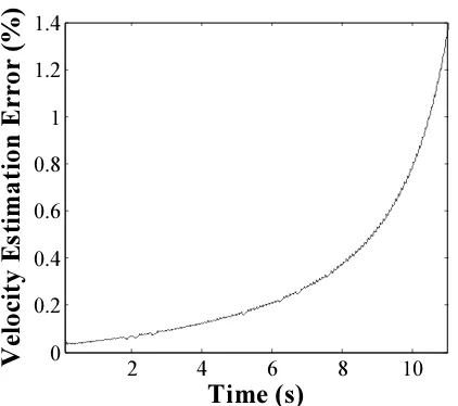
The flowchart of speed observer in different front and rear wheels locking situations is shown in Figure 10. Furthermore in Figure 11, the velocity error (%) of speed observer on icy road has been presented. The maximum error in the estimation of the vehicle velocity is very low (less than 1.4%).
5. RESULTS
The simulation results of the series hybrid electric bus (SHEB) braking performance including stopping distance, regenerated energy, and mean slip ratio of rear and front wheels have been obtained using the anti-lock regenerative braking system (ARBS). In the figures of this section, the vehicle speed is determined from vehicle dynamics model and is not the estimated value obtained from speed observer. It is assumed that the pneumatic brake pressure is constant and around 0.3 bar corresponding to the brake pedal angle of 7° (Figure 8), and that the ABS strategies do not affect the mechanical brake system.
For the brake pedal angle of 7°, icy road condition and initial vehicle speed of 10 (m/s), the results are given in Table 1. As shown in this table, the ARBS, compared to RBS-noABS, can keep the mean rear slip ratio near the critical value of 0.15 and the stopping distance and the regenerated energy have been improved simultaneously.
The source of the regenerated energy (Table 1) is the rear wheels kinetic energy. This kinetic energy depends on the existence of ABS and its controlling method during braking in slippery road conditions. Therefore, in the case of RBS-noABS, the torque is
³
gdt
h
L
L
L
V
V
f r a r b f)
(
)
(
0P
P
P
P
) ( ) ( f r a r b f h L L L g dt dV P P P P2 4 6 8 10
0 0.2 0.4 0.6 0.8 1 1.2 1.4
Time (s)
V
e
lo
ci
ty
Es
ti
m
a
ti
o
n
Erro
r (%)
Fig. 11.Velocity estimation error (%) of speed observer on icy road
Icy road
RBS-noABS
ARBS
Improvement (%)
Stopping Distance (m)
78.65
63.91
18.74
Mean Rear Slip Ratio
0.99
0.15
-
Regenerated Energy (kJ)
53.16
278.9
424.64
Resistor Energy (kJ)
4.45
11.21
-
SoC Difference (%)
0.06
0.30
400
Table 1.Braking performances on icy road condition
constant and high while the wheel is locked and the angular velocity is zero. For that reason, the kinetic energy of the wheel is very low and the total recovered energy is reduced. In the case of ARBS, the torque is controlled based on the value of the slip ratio. In this case, the wheels constantly kept away from being locked and the energy recovery would significantly improve.
Figures 12-13 illustrate the vehicle speed and the equivalent rear (driven) wheels speed during braking. As shown in these figures, the rear wheels are locked in the RBS-noABS strategy (Figure 12), while the ARBS can control the electric motor braking torque to prevent rear wheels from locking (Figure 13).
In Figure 14, the rear wheels slip ratio versus time
charts are presented and compared on icy road condition. The ARBS is successful in preventing vehicle instability by keeping the slip ratio very close to optimal value of 0.15 and consequently increasing the lateral adhesive coefficient (see Figure 4).
Figure 15 shows the EM regenerative braking torque during braking. The regenerative braking torque of EM is constant in the conventional SHEB (“RBS-noABS”). The adaptive behavior (including “increase” and “decrease” modes) of EM braking torque in the ARBS can make the EM braking torque reach the orders of optimal regenerative braking torques in the first two seconds. After this stage, the adaptive modes are repeated to detect possible sudden changes of road condition.
0
5
10
15
0
0.2
0.4
0.6
0.8
1
Time (s)
Slip R
atio
noABS
ARBS
Fig. 14.Rear wheels slip ratio comparison on icy road
0 2 4 6 8 10 12 14 16 0
2000 4000 6000 8000 10000
Time (s)
To
rque (N
.m
)
RBS-noABSARBS
Fig. 15.Regenerative EM torque on icy road
0 2 4 6 8 10 12 14 16
0 2 4 6 8 10
Time (s)
Speed (m
/s
)
Vehicle Speed
Equivalent Rear Wheel Speed
Fig. 12. Vehicle and equivalent rear wheels speed on icy road condition, RBS-noABS
0 2 4 6 8 10 12 14 16
1 2 3 4 5 6 7 8 9 10
Time (s)
Speed (m
/s
)
Vehicle Speed
Equivalent Rear Wheel Speed
Fig. 13. Vehicle and equivalent rear wheels speed on icy road condition, ARBS
In the second test, the asphalt road condition as a non-slippery road is selected and the results are presented in Table 2. In this case, the wheels are not locked during braking. Therefore, all the result of from the ARBS and RBS-noABS are equal. The regenerated energy in this test is greater than the regenerated energy in the previous test although the duration of braking is significantly smaller here than on the icy road condition. Therefore, a large amount of the regenerated energy is dissipated through the resistors because of the battery charge power shortage. Finally, the SoC difference in Table 2 (0.17 %) is dependent on the difference between the regenerated and the resistor dissipated energies (153.0 kJ), similar to Table 1.
Figure 16 illustrates the vehicle speed and the equivalent rear (driven) wheels speed on asphalt road during braking when the ARBS is activated.
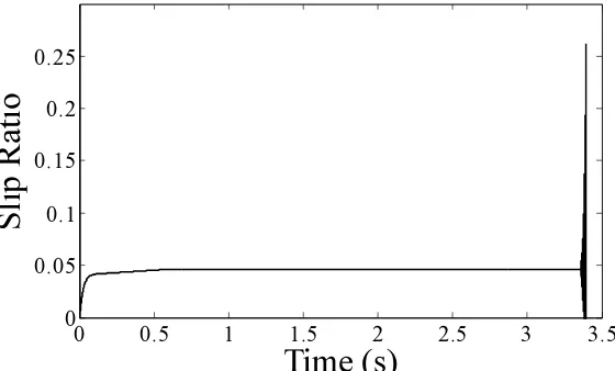
Figure 17 shows the regenerative braking torque of the EM during braking by the ARBS. No fluctuation occurs in the regenerative braking torque of EM on asphalt road because the rear wheels never tend to be locked during braking. The observed curvature in the first 0.5 second of this figure is due to the maximum EM braking torque limitation on above 2500 RPM shaft speed (Figure 6). Figure 18 presents the slip ratio of rear wheels in this case. The figures show that the ARBS can work well even in the non-slippery road conditions.
To create a more realistic road condition, the simulations have been performed on a mixed road condition. The first 10 meters of road is considered slippery (icy road) and the rest is considered dry asphalt road. The vehicle and the equivalent driven wheels speed are shown in figures 19-20, and the regenerative torque of EM is demonstrated in Figure 21.
0 0.5 1 1.5 2 2.5 3
0 2 4 6 8 10
Time (s)
Speed (m
/s
)
Vehicle Speed
Equivalent Rear Wheel Speed
Fig. 16.Vehicle and equivalent rear wheels speed on asphalt road, ARBS
Asphalt Road
Results
Stopping Distance (m)
17.36
Mean Rear Slip
0.08
Regenerated Energy (kJ)
457.3
Resistor Energy (kJ)
304.3
SoC Difference (%)
0.17
Table 2.Braking performances on asphalt road condition
0 0.5 1 1.5 2 2.5 3 3.5 0
2000 4000 6000 8000 10000
Time (s)
Torque
(N.
m
)
Fig. 17.Regenerative EM torques on asphalt road, ARBS
0 0.5 1 1.5 2 2.5 3 3.5
0 0.05 0.1 0.15 0.2 0.25
Time (s)
Slip R
atio
Fig. 18.Rear wheels slip ratio on asphalt road, ARBS
0 1 2 3 4
0 2 4 6 8 10
Time (s)
Speed (m
/s
)
Vehicle Speed
Equivalent Rear Wheel Speed
Fig. 19.Vehicle and equivalent rear wheels speed on complex road condition, ARBS
These figures illustrate that the ARBS is able to control rear wheels speed in both slippery and non-slippery conditions very well. In contrast to “RBS-noABS”, the stability of vehicle is kept by the ARBS in the first 10 meters of mixed road. In addition, the adaptive modes of the ARBS have been successful to detect sudden changes of road condition. The behavior of both systems is almost the same in non-slippery section of mixed road.
The notch of torques curves in Figure 21 is related to maximum EM torques limitation on above 2500 RPM shaft speed (Figure 6). This phenomenon is also evident in Figure 17.
6. CONCLUSIONS
The ABS ability is incorporated into a series hybrid electric bus (SHEB) by utilizing an adaptive rule based control strategy on negative torques of EM during braking. The anti-lock regenerative braking system (ARBS) uses two adaptive modes to establish acceptable ABS and energy regenerative features on different road conditions.
The ARBS demonstrates a reasonable braking performance compared to the conventional regenerative braking system of SHEB in a slippery road condition by decreasing the stopping distance by
0 1 2 3 4
0 2 4 6 8
Time (s)
Speed (m
/s
)
Vehicle Speed
Equivalent Rear Wheel Speed
Fig. 20.Vehicle and equivalent rear wheels speed on complex road condition, RBS-noABS
0 1 2 3 4
0 2000 4000 6000 8000 10000
Time (s)
To
rque (N
.m
)
RBS-noABSARBS
Fig. 21.Regenerative EM torques on complex road condition
at the least 18%. The designed system was also shown to have a good energy recovery performance by almost 400% increase in the regenerated energy.
One feature of the ARBS is utilizing the wheel slip ratio rather than the wheel acceleration as the input of the controller. The slip ratios of the wheels are obtained from the wheel angular velocity from wheel speed sensors and the absolute velocity of the vehicle during braking, which is estimated by the proposed speed observer unit from the values of applied torque and the angular velocities of the wheels. The maximum error in the vehicle velocity estimation by the speed observer is less than 1.4% in a slippery road condition.
REFERENCES
[1] Ye, M., Bai, Z.-F., Cao, B.-G., “Energy recovery
for battery electric vehicles,” Proceedings of the Institution of Mechanical Engineers, Part D: Journal of Automobile Engineering, Volume 222, Issue 10, 2008, pages 1827-1839.
[2] Ehsani, M., Gao, Y., Emadi, A., “Modern
Electric, Hybrid Electric, and Fuel Cell Vehicles,” Second Edition, CRC Press, Taylor and Francis Group, LLC, 2010.
[3] Clarke, P., Muneer, T., Cullinane, K. “Cutting
vehicle emissions with regenerative braking,” 2010, Transportation Research Part D: Transport and Environment 15 (3), pp. 160-167.
[4] Yang, M.-J., Jhou, H.-L., Ma, B.-Y., Shyu,
K.-K., “A cost-effective method of electric brake with energy regeneration for electric vehicles,” (2009) IEEE Transactions on Industrial Electronics, 56 (6), pp. 2203-2212.
[5] Seki, H., Ishihara, K., Tadakuma, S., “Novel
regenerative braking control of electric power-assisted wheelchair for safety downhill road driving,” (2009) IEEE Transactions on Industrial Electronics, 56 (5), pp. 1393-1400.
[6] Gao, Y., Chu, L., Ehsani, M., “Design and
control principles of hybrid braking system for EV, HEV and FCV,” 2007, VPPC 2007 -Proceedings of the 2007 IEEE Vehicle Power and Propulsion Conference, art. No. 4544157, pp. 384-391.
[7] Hori, Y., “Motion control of electric vehicles
and prospects of supercapacitors,” (2009) IEEJ Transactions on Electrical and Electronic
Engineering, 4 (2), pp. 231-239.
[8] Gao, Y., Ehsani, M., “Electronic Braking
System of EV and HEV-Integration of
Regenerative Braking, Automatic Braking Force Control and ABS”, SAE 2001-01-2478, (2001).
[9] Mutoh, N., Hayano, Y., Yahagi, H., Takita, K.,
“Electric braking control methods for electric vehicles with independently driven front and rear wheels,” (2007) IEEE Transactions on Industrial Electronics, 54 (2), pp. 1168-1176. [10] Peng, D., Zhang, Y., Yin, C.-L., Zhang, J.-W.,
“Combined control of a regenerative braking and anti-lock braking system for hybrid electric vehicles,” (2008) International Journal of Automotive Technology, 9 (6), pp. 749-757.
[11] Zhou, L., Luo, Y., Li, K., Lian, X., “Braking
control of electric vehicles while coordinating regenerative and anti-lock brakes,” (2009) Qinghua Daxue Xuebao/Journal of Tsinghua University, 49 (5), pp. 728-732.
[12] Bosch, “Automotive Handbook”, Edition &, Roert Bosch GmbH, Stuttgart, (2007).
[13] Wang, W.-Y., Li, I.-H., Chen, M.-C., Su, S.-F., Hsu, S.-B., “Dynamic slip-ratio estimation and control of anti-lock braking systems using an observer-based direct adaptive fuzzy-neural controller,” (2009) IEEE Transactions on Industrial Electronics, 56 (5), pp. 1746-1756. [14] Esmailzadeh, E., Goodarzi, A., Behmadi, M.,
“Opimized Braking Force Distribution during a Braking-in-Turn Maneuver for Articulated Vehicles,” International Journal of Automotive Engineering, Volume 1, Number 1, 2011, Pages 56-62.
[15] Khatun, P., Bingham, C.M., Schofield, N., Mellor, P.H., “Application of fuzzy control algorithms for electric vehicle anti-lock braking/traction control systems,” (2003) IEEE Transactions on Vehicular Technology, 52 (5), pp. 1356-1364.