Precision cut forage harvester chopper units and
particle length distribution
Mikhail Ivanovich Belov
(Institute of mechanics and energetics, Russian State Agrarian University − Moscow Agricultural Academy by K. A. Timiryazev, Russia, 127550)
Abstract: The main schemes of precision cut forage harvester chopper units were considered. The method was enhanced for
evaluation of particle length distribution for chopped plants provided by cylinder and flywheel type forage harvesters. The effects of the theoretical length of cut, the width of an open throat of a chopper unit and the whole stalk length on percent mass of particles in different diapasons by length were investigated. The accent was made on the length of particles in the range from 8 to 19 mm, suitable for grass ensiling. The theoretical results did not contradict the recommendations for precision cut forage harvesters to set theoretical cut length when harvesting grass for grass haylage. The forage harvesters of this type provide high-quality forage chopping, when relative mass of particles in the range from 8 to 19 mm by length is in the range from 45% to 75%. Calculations showed that theoretical length of cut should be installed in the range from 7 mm to 16 mm to get thеse characteristics. The estimated maximal percent mass of particles ranging in length from 8 mm to 19 mm, is achieved when theoretical cut length is about 8 mm.
Keywords: a forage harvester, a chopper unit, particle length distribution
Citation: Belov, M. I. Precision cut forage harvester chopper units and particle length distribution. 2019. Agricultural Engineering International: CIGR Journal, 21(4): 83–89.
1 Introduction
Numerous studies show that the chopped feed quality depends on the plant chop quality (Bal et al, 2000; Bhandary et al, 2008). The quality of plant chopping provided by a forage harvester, is defined by particle length distribution. It is important to find the theoretical basis of plant chopping regimes for grass haylage and other kinds of feeds. Chopping is the main operation what forage harvester has designed for. Other operations are auxiliary: delivering crop into a chopping unit and diverting crop from a chopping unit.
Chopping systems of modern forage harvesters can be classified in a traditional way: non-precision cut and precision cut chopping systems. Precision cut chopping
Received date: 2018-10-17 Accepted date: 2019-06-10
Biographies:Belov, M., , Ph.D., D.Sc., Professor, Department of
machine parts, Institute of mechanics and energetics, Russian State Agrarian University − Moscow Agricultural Academy by K. A. Timiryazev, 127550, Timiryazevskaya ulitsa, 49, Moscow, Russia. Tel: +7 915 118 20 26, Email: [email protected].
system has feed rolls. Such a system is presented by four designs: 1) a cylinder cutterhead and a separate throw crop accelerator; 2) a cylinder cutterhead and a separate blower with an auger between them; 3) a cut and throw cylinder cutterhead; 4) a flywheel cut and throw cutterhead.
1. The conventional cut and blow forage harvesters have been modernized. The modern cut and blow forage harvester uses a cylinder cutterhead for crop chopping and a crop accelerator for forage throwing through a discharge spout. Feed rolls 1 press crop and push it through an open throat on a shearbar 2 and into a cutterhead 3 (Figures 1-2). Paddles of a crop accelerator 4 capture forage and throw particles of crop into a discharge spout 5. Two rolls 6 of a kernel processor are installed when there is need to crack and crush kernels and cobs.
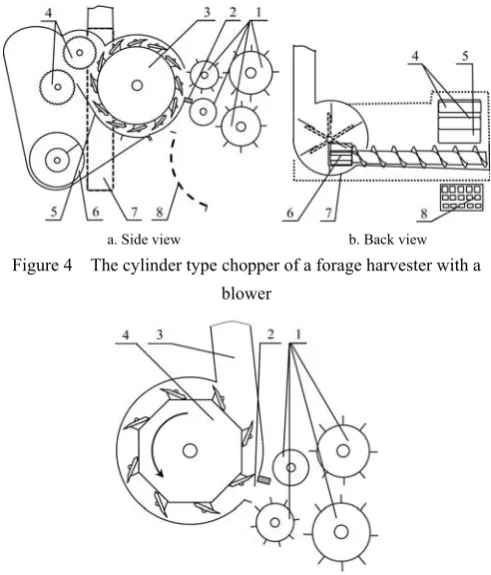
(Figures 3-4). An auger 6 delivers forage from a cutterhead to a blower 7. A cutterhead house bottom 5 and rolls 4 of a corn processor are installed when there is need to crack and crush kernels and cobs. Recutter screens as optional equipment can be included in a cylinder type non-processor chopper. A recutter 8 is installed in the place 5 between a cutterhead and an auger. Five recutters are available.
3. Nonconventional cut and throw forage harvesters with upper cut system are still used. Feed rolls 1 press crop and push it through an open throat on a shearbar 2 and into a cutterhead 4 (Figure 5). Knives of a cylinder cutterhead cut the crop at the high positioned shearbar and throw it directly into the stout 3 without any friction between crop particles and a cutterhead house walls.
a. A kernel processor uninstalled b. A kernel processor installed
Figure 1 Precision cut chopping system with a cylinder cutterhead and a crop accelerator of a self propelled forage harvester
Figure 2 Precision cut chopping system of a trailed forage harvester
a. Side view b. Back view
Figure 3 The cylinder type chopper of a forage harvester with a blower
a. Side view b. Back view
Figure 4 The cylinder type chopper of a forage harvester with a blower
Figure 5 A chopper system with a cylinder cut and throw cutterhead
4. A flywheel-type chopper is used in mounted and trailed forage harvesters. Feed rolls 1 press crop and push it through an open throat on a shearbar 2 and into a flywheel cut and throw cutterhead 3 house (Figure 6). A cutterhead contains radial paddles 6 for better throwing crop into a pipe 4. For better corn cob chopping smooth working surfaces of paddles 6 and bottom 5 are replaced by wavy working surfaces or cracked section plates.
Figure 6 A chopper system with a flywheel cut and throw cutterhead
Table 1 Specifications of precision cut forage harvester cutterheads
Model(s)/company (reference) Figure D, mm ω, rpm n Wc, mm lc, mm
FP 230/New Holland (New Holland, n.d. a) 4 533.4 850 12 558.8 4,8/6.4/8/9.5/11.1
FP 230/New Holland (New Holland, n.d. a) 4 533.4 850 8 558.8 7.1/9.5/11.1/14.3/16.7
Fp240/New Holland (New Holland, n.d. a) 4 533.4 850 12 619.8 4.8/6.4/8/9.5/11.1
Fp240/New Holland (New Holland, n.d. a) 4 533.4 850 8 619.8 7.1/9.5/11.1/14.3/16.7
3955/John Deere (John Deere, n.d. a) 3 457 850 12 457 6.0− 25.4
3975/John Deere (John Deere, n.d. a) 3 457 850 12 559 6.0− 25.4
FHX300/ Case IH (Case IH, n.d.) 3 533 850 12 619.8 4.8−11.1
F−41/DION (Dion -Ag Inc., n.d.) 2 560 730 12 690 na
F−41, DION (Dion -Ag Inc., n.d.) 2 560 824 12 690 na
F−41, DION (Dion -Ag Inc., n.d.) 2 560 1033 12 690 na
F−41 Stinger, DION (Dion -Ag Inc., n.d.) 2 560 1033 12 690 na
FC860, FCT960, FCT1060/ Kongskilde (Kongskilde, n.d.) 5 480 1600 6 720 5.7/7.2/8.5/10/12/14.3/16.6 FCT1260 (FCT1260MD)/ Kongskilde (Kongskilde, n.d.) 5 480 1600 6 720 21/13 (21/16) FCT1260 (FCT1260MD)/ Kongskilde (Kongskilde, n.d.) 5 480 1600 8 720 15/9 (16/12)
FCT1460MD/Kongskilde (Kongskilde, 2018) 5 480 1600 10 900 16 maximum
FCT1360/Kongskilde (Kongskilde, 2018) 5 480 1600 10 900 7/15 standard
FCT1460/Kongskilde (Kongskilde, 2018) 5 480 1600 10 900 12/16 standard (6/8 optional)
Mex5/Pottinger (Pottinger, n.d.) 6 na 5/7/9/11/15/19
Mex6/Pottinger (Pottinger, n.d.) 6 na 5/7/9/11/15/19
FR450, FR500, FR600, FR700, FR850/New Holland
(New Holland, 2018b) 1 710/690 1130 6; 8; 12; 16; 20 860 8-44; 6-33; 4-22; 3-16; 2-13
8100, 8200, 8300, 8400, 8500/ John Deere (John Deere,
n.d. b) 1 668 1100 10; 12 678 7-26; 6-22
8600, 8700, 8800/John Deere (John Deere, n.d. b) 1 668 1100 10; 12 851 7-26; 6-22
Big X 480, 530, 580, 630/Krone (Krone, 2018) 1 660 na 10; 14; 18; 20 630 5-31; 4-22; 3-17; 2.5-15 (0.5 mm increments)
Big X 680, 780, 880/Krone (Krone, 2018) 1 660 na 10; 14; 18; 20; 24 800 5-31; 4-22; 3-17; 2.5-15 ; 2-12 (0.5 mm increments)
Big X 700, 770/Krone (Krone, 2018) 1 660 na 10; 14; 18; 20 800 5-29; 4-21; 3-17; 2.5-15 Big X 850, 1100/Krone (Krone, 2018) 1 660 na 10; 14; 18; 20; 24 800 5-29; 4-21; 3-17; 2.5-15; 2-12.5
Jaguar 870, 860, 850, 840/Claas (Claas, 2018 a) 1 630 1200 10; 12; 14 730 5/6.5/8.5/11/17/21; 4/5.5/7/9/14/17; 3.5/4.5/6/8/12/15
Jaguar 900 series/Claas (Claas, 2018 b) 1 na na na na any required
RSM 1403, 1401/Rostselmash (Rostselmash, n.d.) 1 630 1200 12 680 4/7/10/17
Don 680M/Rostselmash (Rostselmash, n.d.) 1 750 838 12 680 3.5/8/20
Katana 65, 68/Fendt (Fendt, n.d.) 1 720 1150 7; 10; 14; 20 800 7.4-41.4; 5.2-29; 3.7-20.7;2.6-14.5
2 Theory and methods
2.1 The task
The purpose of this research is to develop an algorithm to assess the particle length distribution for chopped plants on the basis of mathematical model of chopping by a forage harvester, supplied with a cylinder or a flywheel cutterhead. The length of cut has an impact on the chopped forage quality. Current recommendations for grass ensiling are grass harvesting at the theoretical cut length of 6.3 to 12.7 mm to ensure the quality of chopping, at which the relative mass of forage particles in the middle sieve of Penn state forage particle separator is 45%-75% (Jones et al., 2004; Wiersma, 2013). In this case, the length of each particle should be in the range
from 8 to 19 mm. The consequent task was to investigate the effects of the theoretical length of cut and the width of an open throat on the percent mass of stalk particles in the range from 8 to 19 mm by length.
The theme of particle length distributions for plants chopped by precision cut forage harvesters is not new (Szendro, 1979; Saqib and Finner, 1982; O'Dogherty, 1984; Morgan et al., 1984; Bietresato et al, 2013). In the above papers, questions of evaluating the effect of the width of an open throat on the length of the chopped forage particles were not considered.
2.2 Denotes
particles the lengths of which are in the range from 0 to L, kg; MT – the total mass of all particle, kg; mL – percent mass of particles in the range from 0 to L by length; m – percent mass of particles in the range from 8 to 19 mm by
length.
2.3 Calculation of particle length and particle mass
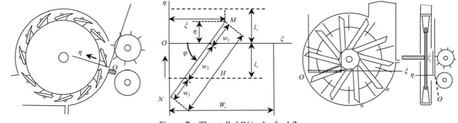
Let us consider the stalk MN by the length of H at the moment of entry into a cutterhead (Figure 7).
Figure 7 The stalk MN in the feed flow
Let us input the Cartesian coordinate system Oξ in the feed flow, where the axis Oξ is tied with a shearbar. It was supposed, that the blade of a knife was the direct line and each blade took position on the axis Oξ periodically.
The stalk MN in the feed flow was considered at those moments when the blade takes position on the axis Oξ
and the feed flow was pressed. When the front point M takes place in a housing of a cylinder or a flywheel cutterhead, the position of the stalk MN can be defined by the coordinates ξ, η of the point M and the angle φ
between the axis Oξ and the cut MN. It was accepted, that the independent random variables ξ, η, φ were uniformly distributed on the intervals [0, Wc], [0, lc] and [φ1, φ2]
respectively (Polyanin and Manzhirov, 2006):
0 < ξ≤ Wc (1) 0 < η≤ lc (2)
φ1≤φ≤φ2 (3)
where values φ1, φ2 depend of ξ:
1
0, if arccos( / ), if
H ξ
φ
ξ H H ξ
≤ ⎧
= ⎨ >
⎩ (4)
2
, if
arccos[( ) / ], if 2
c
c c
π H W ξ
φ π
W ξ H H W ξ
≤ −
⎧ ⎪
= ⎨ + − > −
⎪⎩ (5)
The variables ξ, η, φ can be determined on intervals of boundary conditions (Equations (1)-(3)) with any accuracy by the formulas
ξ=iWc/nξ (6)
η=jlc/nη (7)
φ=φ1+q(φ2–φ1)/nφ (8)
where nξ, nη, nφ – the specified integers; i, j, q – integers
(1 ≤ i ≤ nξ; 1 ≤ j ≤ nη; 1 ≤ q ≤ nφ).
Let l be the length of high part of the stalk, M(l) – the mass of this part. It was assumed that the plant density ρ
per length unit at some point (section) increased directly proportional to the distance y between the top of stalk and the section:
ρ = a y; M(l) = a l2/2 where, a – the coefficient of proportionality.
Then the mass of any stalk part the length of which is
Δ can be calculated by the formula m(l, Δ) = M(l + Δ) − M(l) or
m(l, Δ) =a[(l + Δ)2 – l2]/2
(9) where, l is a distance between the top of the stalk and the stalk part.
By definition,
mL = 100 ML /MT. (10) It can be seen from the Equation (9), that mL does not depend on coefficient a. Therefore, it can be accepted a = 1 for calculating mL and ML, MT.
By definition,
m=mL|L=19 mm –mL|L=8 mm (11)
When a forage harvester is equipped with a cutter, the front point M is the lowest point of a stalk in the feed flow. When the forage harvester is equipped with a pick-up, the front point M can be the low point or the high point of the stalk with the probability 0.5.
The stalk MN is cut, if the cut MN crosses the axis Oξ. The number n of the particle parts, formed from the stalk MN for a few cuts, can be calculated as follows:
1, if sin [( sin ) / ] 2, if sinc
H φ η
n
H φ η l H φ η
≤ ⎧
= ⎨ − + >
In accordance with the law of distribution of random variables ξ, η, φ the integers i, j, q in the Equations (6)-(8) are equal to any integer number from 1 to nξ, from 1 to nη,
from 1 to nφ with the probability 1/nξ, 1/nη, 1/nφ
respectively. Values φ1, φ2 are defined by Equations (4)-
(5) and depend of i. When the number of cycles is equaled to product (nξ nη nφ), the combination of integers
i, j, q takes all possible values.
Let us denote the length and the mass of the part under number u as wu, mu (u – integer, 1 ≤ u ≤ n). Let us write out representations of variables wu, mu, if values H, φ, η, lc are given.
If n = 1 or H sin φ < η, the plant MN is not cut and the length w1 and the mass m1 of the lonely particle 1 are the
length and the mass of whole plant:
w1 = H; m1 = w12/2 (13)
If n = 2, the plant MN is cut on two parts (particles). The lengths w1, w2 of two parts can be find geometrically
(Figure 7):
w1 = η/sinφ; w2 = H − w1 (14)
The masses of two particles for harvester, equipped with a cutter, can be calculated by Equation (9) at a = 1:
m2 = w22/2; m1 = [(w1+ w2)2 – w22]/2 (15)
When n > 2, the particle MN is cut on n new formed parts. The lengths of these parts can be determined by the next formulas:
w1 = η/sin φ; wj = lc/sin φ;
1 1 n
n u u
w =H−
∑
−= w (16)where, j – integer (2 ≤ j ≤ n−1).
The masses of n particles for harvester, equipped with a cutter, can be calculated by Equation (9) at a = 1:
2 2
1
( n ) ( n ) / 2
k p k p p k p
m =⎡⎣
∑
= w −∑
= + w ⎤⎦ (17)where, 1 ≤ k ≤ n.
2.4 Value mL calculation algorithm
1. Assignment of values of variables Wc, H, lc, L and initial values ML, MT (ML = 0, MT = 0).
2. Assignment of constants nξ, nη, nφ and the variable i
as i = 1.
3. Calculations of the value ξ by Equation (6) and the values φ1, φ2 by Equations (4)-(5).
4. Assignment of the variable j as j = 1.
5. Calculation of the value η by the Equation (7). 6. Assignment of the variable q as q = 1.
7. Calculations of the value φ by the Equation (8) and the value n by the Equation (12).
8. Calculation of the values w1, m1 by the Equation
(13), if n = 1, or the values w1, w2 by the Equation (14), if
n = 2, or the values wk for all integer k in the range from 2 to n by the Equation (16), if n > 2.
9. Calculation of the values m1, m2 by the Equation
(15), if n = 2, or the values mk for all integer k in the range from 2 to n by the Equation (17), if n > 2.
10. Increase in the amount of the value MT by the value m1, if n = 1, or by the values m1 and m2, if n = 2, or
by the values mk for all integer k in the range from 1 to n, if n > 2.
11. Increase in the amount of the value ML by mi, if wi≤ L for all integer i in the range from 1 to n.
12. Increase in the amount of the variable q by 1 and repetition of the actions in the items 7, 8, 9, 10, 11, if φ <
φ2.
13. Increase in the amount of the variable j by 1 and repetition of the actions in the items 5, 6, 7, 8, 9, 10, 11, 12, if η < lc.
14. Increase in the amount of the variable i by 1 and repetition of the actions in the items 3, 4, 5, 6, 7, 8, 9, 10, 11, 12, 13, if ξ≤ Wc.
15. Calculation of the value mL by the Equation (10).
3 Results and discussion
The program environment ‘Lazarus’ (Free Pascal Lazarus project, Version #: 1.8.0) was used to compute the value mL by the presented algorithm and the value m by the Equation (14). The source data are placed in the Table 2.
Table 2 Given values
Wc, mm H, mm lc, mm nξ nη nφ
680 300, 400, 600 7,7; 13,7 20 10 200
Calculations showed that percent mass mL had different properties in two intervals of argument L. In the first interval, where L ranged from zero to theoretical cut length, the function increased slowly. In the second interval, where L ranged from theoretical cut length to maximal length of particles, there was rapid increasing of the percent mass (Figure 8).
grass for haylage when theoretical length of cut ranged from 7 mm to 16 mm (Figure 9).
(a) (b)
Figure 8 Effect of L on mL with results of field tests of forage harvesters KSK-100 and KPKU-75 on chopping cereals for haylage (a) and
results of laboratory tests of a chopper of forage harvester KSK-100 (b)
1 – lc = 7.7 mm; H =300 mm; ● – experimental data (Belov, 1983); 2 – lc = 13.7 mm; H =300 mm; ■, ▲ – experimental data; 3 – lc = 13.7 mm; H = 400 mm; ● – experimental data on chopping vico-oat mixture; 4 – lc = 13.7 mm; H = 600 mm; ■ – experimental data on chopping corn; 5 – lc = 13.7 mm; H =300 mm; ▼– experimental data on chopping straw.
(a) 350 mm (b) 700 mm
1 – Wc =450 mm; 2 – Wc = 600 mm; 3 – Wc = 900 mm
Figure 9 Effect of lc on m at the different open throat width and at the length of stalks These results do not contradict the recommendation to
choose the theoretical length of cut for grass ensiling from 6.3 mm to 12.7 mm (Wiersma, 2013).
It can be also seen that maximal percent mass of particles in the limits from 8 mm to 19 mm is achieved when theoretical cut length is about 8 mm.
According to the considered model open throat width of chopper unit and stalk length also affect the percent mass. Increase of stalk length or decrease of the width of an open throat allows to increase percent mass of particles in diapason from 8 mm to 19 mm by length.
4 Conclusions
1. At theoretical length of cut in the range from 7 mm to 17 mm the precision cut forage harvesters can provide
recommended percent mass of particles, the lengths of which exceed 8 mm and do not exceed 19 mm, in the limits from 45% to 75%.
2. The theoretical results do not contradict the recommendation to choose the theoretical length of cut for grass ensiling between 6,3 mm and 12,7 mm.
3. The estimated maximal percent mass of particles ranging in length from 8 mm to 19 mm, is achieved when theoretical cut length is about 8 mm.
References
Bal, M. A., R. D. Shaver, A. G. Jirovec, and J. G. Coors. 2000. Crop processing and chop length of corn silage: Effects on intake, digestion, and milk Production by dairy cows. Journal of Diary Science, 83(6): 1264–1273.
forage harvesters. Ph.D. diss., Moscow All-Union scientifically-research Institute of agricultural engineering. (In Russian)
Bhandary, S. K., S. Li, K. M. Ominsky, K. M. Wittenberg, and J. C. Plaizier. 2008. Effects of the chop lengths of alfalfa silage and oat silage on feed Intake, milk production, feeding behavior, and rumen fermentation of dairy cows. Journal of Dairy Science, 91(5): 1942–1958.
Bietresato, M., S. Pavan, G. Cozzi, and L. Sartori. 2013. A numerical approach for evaluating and properly setting self-propelled forage harvesters. Transactions of the ASABE, 56(1): 5–14.
Case IH. 2018. Products/Forage Harvesters&Blowers/Pull-type forage harvester. Available at: https://www.caseih.com/ northamerica/en-us. Accessed 23 April 2018.
Claas. n.d. Products/Forage harvesters. Available at: http://www.claas.co.uk/products/forage-harvesters. Accessed 2 May 2018.
Claas. n.d. Forage harvesters. Jaguar 900 series. Available at: http://www.claasofamerica.com/blueprint/servlet/blob/148240 2/464633b5c850cee6440d462c153b7818/302360-dataRaw.pd f. Accessed 8 May 2018.
Dion -Ag Inc. n.d. Forage harvesters F41 & F41 Stinger. Available at: http://www.dion-ag.com/eng/pdf/Dion_F41_Forage_ Harvester.pdf. Accessed 23 April 2018.
Fendt. n.d. Fendt Katana. Available at: https://www.fendt.com/int/geneva-assets/article/28405/13846 3-fendtkatana-09-2017-td-en.pdf. Accessed 10 May 2018. John Deere. 2018. Hay and forage harvesting equipment. Available
at: https://www.deere.com/en/hay-forage/harvesting/. Accessed 19 April 2018.
John Deere. n.d. 8000 Series. Model Specifications. Available at: https://www.deere.com.au/en/magazines/publication.html?id= c41fa6af#80. Accessed 1 May 2018.
Jones, C. M., A. J. Heinrichs, G. W. Roth, and V. A.Ishler. 2004. From harvest to feed: understanding silage management. Available at: http://pss.uvm.edu/pdpforage/Materials/ CuttingMgt/From_Harvest_to_Feed_Understanding_Silage_m anagement_PennState.pdf. Accessed 20 April 2018.
Kongskilde. n.d. Forage harvesters. Available at: http://www.kongskilde.com/Agriculture/Grass%20and%20Co mplete%20Diet%20Mixers/Forage%20Harvesters. Accessed
25 April 2018.
Krone. 2018. Products/Forage harvester/Big X. Available at: http://www.krone-uk.com/english/products/forage-harvester. Accessed 2 May 2018.
Morgan, D. D. V., M. M. Osman, and S. J. Hickman. 1984. A mathematical model of an apparatus for the assessment of the length distribution of chopped forage. Journal of Agricultural Engineering Research, 30: 157–164.
New Holland. n.d. Pull type forage harvesters and flail harvester. Available at: http://d3u1quraki94yp.cloudfront.net/nhag/ nar/en-us/assets/pdf/hay-tools/pull-type-forageharvester
-brochure -us-en.pdf. Accessed 19 April 2018.
New Holland. n.d. New Holland FR. Available at: http://d3u1quraki94yp.cloudfront.net/nhag/apac/en-in/assets/p df/hay-and-forage/fr-brochure-apac-en.pdf. Accessed 1 May 2018.
O’Dogherty M. J. 1984. Chop length distributions from forage harvesters and a simulation model of chopping. Journal of Agricultural Engineering Research, 30: 165–173.
Polyanin, A. D., and A. V. Manzhirov. 2006. Handbook of Mathematics for Engineers and Scientists. 1st ed., pp.1051. Boca Raton, London, New York: Chapman & Hall/CRC Taylor & Francis Group.
Pottinger. n.d. MEX Pottinger flywheel forage harvesters. Available at: https://www.poettinger.at/download/prospekte/ POETTINGER_MEX-_160.EN.0115.pdf. Accessed 30 April 2018.
Rostselmash, n. d. Products/Forage harvester. Available at: https://en.rostselmash.com/products/forage_harvesters. Accessed 10 May 2018.
Saqib, G. S., and M. F. Finner. 1982. Simulated ideal length of cut for forage harvesters. Transections of the ASABE, 25(5): 1237–1238.
Szendro P.1979. Examination of chopping process in self propelled forage harvesters: mathematical analysis of distribution of cut length. Acta Agronomy Academy Scientific Hungary, 28(1-2): 106–119.
Wiersma D. 2013. Theoretical length of cut: Theory and practice. Progressive diary man. Available at: https://www.progressivedairycanada.com/topics/feed-nutrition /theoretical-length-of-cut-theory-and-practice. Accessed 24 May 2018.
Funding: This research did not receive any specific grant from funding agencies in the public, commercial or