Implementation and Validation of a New Strategy of
Online Practical Works of Power Electronics for
Embedded Systems
https://doi.org/10.3991/ijoe.v13i04.6659Abdessamad Malaoui
Sultan Moulay Slimane University, Béni Mellal, Morocco [email protected]
Monji Kherallah
University of Sfax, REGIM-Lab, Sfax, Tunisia [email protected]
Lila Ghomri
Abdelhamid Ibn badis University, Mostaganem, Algeria [email protected]
Mustapha Raoufi
University of Cadi Ayyad, Marrakech, Morocco [email protected]
Guillaume Andrieu University of Limoges, France [email protected]
Thomas Fredon University of Limoges, France [email protected]
Denis Barataud University of Limoges, France [email protected]
The results are presented and discussed according to two levels. The first is a comparison of the results of electronic measurements with the theory. The se-cond deals with comparison of this Remote system with the same PW per-formed by the classical method "in-class". Based on an analysis of the students Quality Assessment of these PWs, the results show the limits of validity and re-veal the strengths and weaknesses of this new educational strategy in the Uni-versity pedagogical system, and the possibility of its used in other types of training and disciplines.
Keywords—Remote Laboratory, Online Practical Works, e-Learning, Embed-ded Systems, Power Electronics, EOLES Project
1
Introduction
The courses and disciplines in the exact sciences are based on practical work which complements the theoretical teaching. In recent years, there have been anomalies in these formations in southern Mediterranean countries, particularly in open access institutions [1]. The high and growing number of students enrolled in these courses is the main factor in this imbalance, but there are also other factors such as the inade-quacy of teaching skills in some disciplines and the high cost of practical teaching materials.
In recent years, researchers in this field have proposed several approaches and strategies to help find solutions to these challenges [2]. Most of these strategies are based on distance education and the use of Information Technologies (IT) and the remarkable development of embedded electronic systems [3]. The first problem in this type of education is the development of Practical Works, which really requires a serious thought to integrate this new educational approach and the adaptation of em-bedded systems in the remotely controlled laboratory.
In this work, we present an innovative experience mounted by an international pro-ject between several European and the Maghreb countries, to implement an educa-tional laboratory of Remote Practical Work (PW) in the power electronics field for embedded systems [4]. This experience is validated by qualified international training bringing together dozens of students from these countries in a professional Bachelor (Electronics and Optics e-Learning for Embedded Systems) [5]. EOLES members skills were trained through this project to make and to install the hardware and soft-ware tools for Remote practical works, as well as coaching and teaching these PWs either synchronously or/and through developed and registered courses in a platform.
2
Framework and description of Remote Practical Works
The EOLES project (Electronics and Optics e-Learning for Embedded Systems) is a European project (Tempus) who aims support the development of e-learning (dis-tance learning) in Algeria, Morocco and Tunisia through the creation of a third year bachelor in electronics and optics, taught entirely in English. This 3rd year of license is opened to all students regardless of their place of residence [6]. The first two years of the project were devoted to the development of equipment education (courses, practi-cal work, etc.) and the development of Remote laboratory perspective as the concrete implementation of the Diploma in the last year of project.
The most innovative point of this project is the creation of a remote practical labor-atory work fully online. This educative project is coordinated by the University of Limoges, it was have received a 1,28M! funding from the European Union under the Tempus program. This project aims to create a diploma in third year in electronics and optics for embedded systems, taught in English. The most point’s innovation of this project is the creation of a practical Remote laboratory. The diploma obtained by students is a joint diploma delivered by several consortium partners. EOLES was a 3 years project and it brings together 15 partner universities from seven Mediterranean countries (Algeria, Belgium, France, Morocco, Portugal, Romania and Tunisia). Vali-dation and implementation of this project proves a best ability management to im-plement innovative proposals both in the scientific and pedagogical:
• Establishment of a training accessible entirely online including the realization of practical work online,
• Training modules also offered to teachers and staff involved,
• Use of social networks to enable exchange and mutual assistance between stu-dents.
3
Architectures of Practical Works implementation
Fig. 1. Overall architecture of server connections
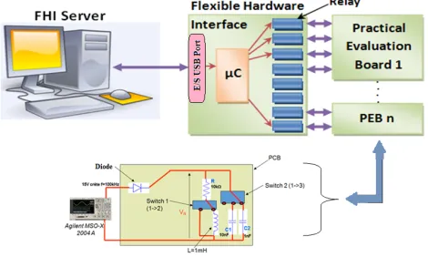
The architecture in the interior of each laboratory has a main server connected to a relay matrix system that controls manipulations using an embedded system "Arduino" or "PCduino" and measuring power devices (oscilloscope, GBF ...). The web interface design uses HTML (CSS) and JavaScript [7, 8]. The PW is graphically represented in web pages. Figure 2 illustrates the hardware architecture of the connection and the practical works.
Fig. 2. Example of a Remote Practical Evaluation Board (PEB) architecture
4
Used equipments in Remote Practical Laboratory
4.1 Measuring devices and Evaluation Board
The implemented laboratory architecture is centered on a main server and uses many other types of equipment to be correctly connected [9]. This server is connected to several measuring devices and instruments such as:
• Switches remotely controlled by the student “1 toward 3”,
• Printed circuit board containing the different components and relays controlled with an Ethernet Hardware Interface (EFHI) using embedded systems as Arduino.
• Waveform generator 33220A.
• 4 channel Digital oscilloscope DSOX3014 or MSOX2004A. The generator em-bedded in this oscilloscope drives the circuit and VR is measured with the part of the scope for each circuit configuration.
Those devices can be monitored from the different application server. This architec-ture has several advantages as the flexibility to control a large number of instruments and Remote Practical Evaluation Board (PEB) locally developed [10]. Also it is transparent to the user, which exactly the case when several instruments are used locally. Indeed the user will not need to know the nature of interface used on each instrument remotely controlled. On the other hand, the possibility to remotely control instruments, relays and others manipulations.
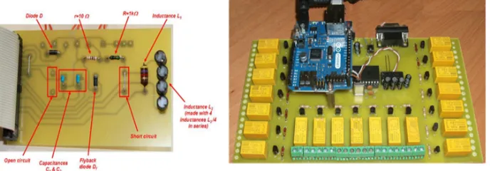
In Figure 3, we present the electronic circuit of a practical evaluation board in our PW. The passive elements of this circuit are controlled by relays and the matrix of different values (resistances, capacities and inductances) allows wiring of the desired electronic circuit diagram.
Fig. 3. Electronic schematic and realized Practical Evaluation Board (PEB)
4.2 Software interface and learning equipments of PW
The Learning Environment (LE) and developed Remote laboratory use the online classrooms at each institute of the partner countries, connected to the internet. It con-tains the following components:
• Camera, Microphone, writing board, speaker ….
This server helps to connect students, lecturers and tutors to Moodle learning plat-form.
• Remote lab servers installed in each Remote lab (Morocco, Tunisia and Algeria).
• Measuring equipment, DUT’s, connections between equipment, measurement probes, software…
• Several PC’s (and Arduino) “serving” the Laboratory set-ups.
4.3 Practical Works steps
Different steps are necessary to realize a practical work:
• Thinking (by Teacher) about the electronic circuit, its scheme and all different possible configurations allowed for the students,
• Conceiving the circuit, soldering the components, assembling the case,
• Programming the web page and all the possible configurations,
• Technical staff in each University plugging all the instruments to the case. For a student, a practical work is composed of several links:
• One to each instrument’s interface.
• One to the practical work’s schematic.
• One to the IP-webcam.
• One to the practical work’s text, written by the teachers.
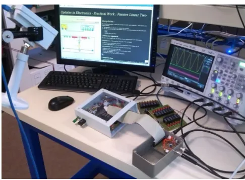
The image of Fig. 4 shows the assembly of the remotely controlled mounting.
Fig. 4. Practical Works equipments
5
Developed Practical Works
PW1: Uncontrolled single-phase half wave rectifier.
In figure 5, we present the electronic schema that corresponds to the first practical work (PW1).
Fig. 5. Schema and interface of PW1
The objective of this PW is to manipulate an uncontrolled single-phase rectifier con-nected to different loads (R, C and L). The tasks asked of the students are presented and explained later.
PW2: Uncontrolled single-phase full wave rectifier.
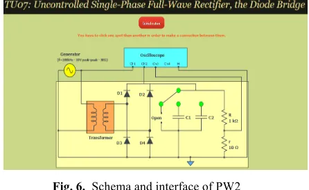
The objective of this second practical works (WP2) is to study the full-wave recti-fier with different loads. Figure 6 shows the electronic schema and the online plat-form of this PW. In the same way, the tasks asked of the students are presented and explained later.
Fig. 6. Schema and interface of PW2
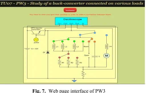
PW3: Study of a Buck-converter connected on various loads.
Fig. 7. Web page interface of PW3
Before beginning the manipulations, one must configure the waveform generator under the following values:
• Waveform: sinusoidal and frequency about 10 kHz.
• Magnitude: 10 V peak-peak.
For two Practical Works (PW1 and PW2) the required tasks of the students are the measurement of current and voltage characteristics to determine:
• Measurement of <Vs> = f (") with a mean current Ie.
• Measurement of <Vs> = f (<Is >) with a constant duty cycle.
• Measurement of Vs and for the discontinuity condition of the current. • Plot of Is=f(t) graph.
The Vs, Is, and " are respectively output voltage, output current in load and duty ratio. The student must explain how is it possible to know the current iR(t) through the load with the resistance “r”. To achieve these tasks, the student must perform tree manipu-lations:
! Manipulation 1: with resistive load (Z= R).
The student is asked to perform the following tasks:
• Connect the load R at the output of diode (green switch on open, red switch on short).
• Measure <VR>, VRMS, the form factor F and the ripple rate #. Is it possible to measure the threshold voltage of the diode (voltage between the anode and the cath-ode of a dicath-ode when the dicath-ode is "ON")?
• Justify and give your results.
The theoretical expressions of the measured parameters during PWs are given by: - The mean value of the output voltage of VR is:
! !!!!!! ! ! !" (1)
!!"#! !! !!!! ! !! (2)
The factor F and the ripple rate # are given by:
!!!!"#
!!!! (3)
! !!!"#!!!"#
!!!! (4)
! Manipulation 2: with R in parallel with a capacitance C (Z=R//C).
Similarly, the student must perform:
• Connect successively capacitances C1 and C2 in parallel with the load R.
• After observing the rectified voltage VR obtained for each capacitance, what is the best capacitance between C1 and C2? Justify.
• Then, measure <VR>, VRMS, the factor form F and the ripple rate # for the optimal capacitance. Compare with the results obtained with the load R. For this optimal ca-pacitance, what is the ratio between the times when the diode is ON in comparison to the period T of the signal? Thus, indicate if the current through the load iR(t) and the rectified voltage VR(t) are in phase.
The output capacity C is given by:
! ! !!
!!!"!!!!"#!!"#! (5)
Where t1 is time when V(t1)=Vmin.
! Manipulation 3: Load R in serie with an inductance, the RL load being in
paral-lel with a diode
Students must follow the following steps:
• Connect successively inductances L1 and L2 in serie with the load R.
• Connect also the flyback diode Df in parallel to the RL load.
• Say what is the role of this diode Df? Is it playing correctly its role? Justify.
6
Results and discussions
6.1 Results of electronic measurements
In three practical works, students determine electrical quantities with different methods using the Remote oscilloscope measurements and theories. Several results have been obtained according to the 3 manipulations indicated in paragraph 5, but it will be limited to giving just some results of these measures. Indeed, we will present 3 significant cases of these results:
Results 1: Single-phase half wave rectifier on various resistive load.
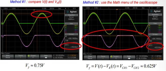
The voltage value of the threshold voltage of the diode (voltage between the anode and the cathode of a diode when the diode is "ON") is measured using two methods. The first method use the Math menu of the oscilloscope and second method compares V(t) and VR(t) voltage based on the current measurements as shown in figure 8. These results are compared with theory and presented in Table 1. It show the difference justified by measurement. We also compare the theory with other measured electrical quantities (<VR>, VRMS, F, Vmax, Vmin and !). The values of this comparison are
pre-sented in Table 2.
Fig. 8. PW measurements in Manipulation 1
Table 1. Comparison of the threshold voltage of the diode
Method 1 Method 2 Theory
V" (volts) 0,75 0.625 0,7
Table 2. Comparison of parameters measurement Measurements In theory (ideal diode)
<VR> 2.73 V 3.18 V
VRRMS 4.38 V 5 V
Vmax 9 V 10 V
Vmin 0 V 0 V
F 1.6 1.57
These results show logical differences between measurements and theory. The differ-ences of these values remain in the same level in the conventional PW.
Results 2: Single-phase half wave rectifier on various loads (Z=R//C)
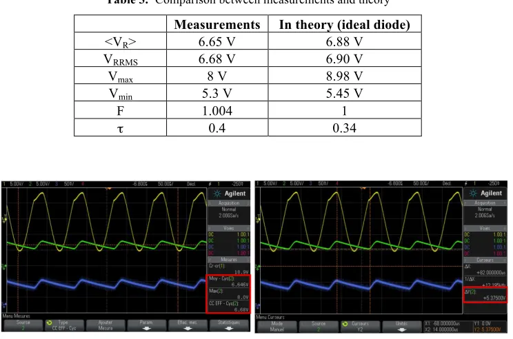
The student must seek by measure, the optimal capacitance C at the output of the assembly (PW2) which gives good filtering. The measurements of the parameters <VR>, VRMS, F and ! for the best capacitance of C have given in Fig. 9 and Table 3:
Table 3. Comparison between measurements and theory Measurements In theory (ideal diode)
<VR> 6.65 V 6.88 V
VRRMS 6.68 V 6.90 V
Vmax 8 V 8.98 V
Vmin 5.3 V 5.45 V
F 1.004 1
! 0.4 0.34
Fig. 9. PW measurements in Manipulation 2
For this optimal capacitance, students can determine the ratio between the time (T”ON”) when the diode is “ON” in comparison to the period “T” of the signal. They can also verify if the current through the load iR(t) and the rectified voltage VR(t) are in phase. The values and equations of these tasks are:
T”OFF”=82 $s
Fig. 10. Determination of optimal capacitance in Manipulation 2
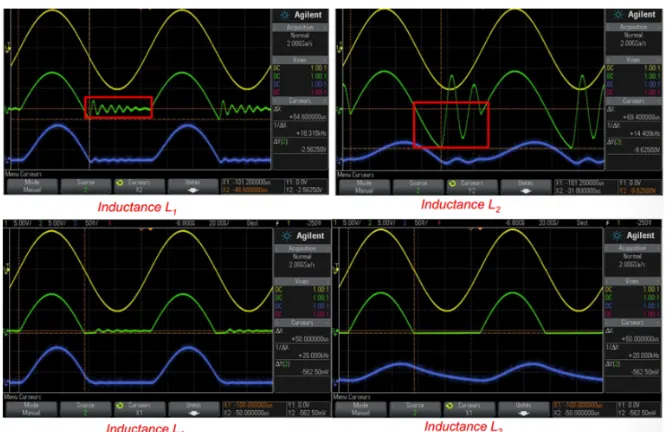
Results 3 : Load R in serie with inductance L, the RL load being in parallel with
a diode
In this manipulation, students can measure if the current through the load iR(t) and the rectified voltage VR(t) are in phase. They can also verify the origin of the problem concerning the rectified voltage VR(t). They show the effect of the optimal value of the inductance (L1 and L2) on the signal stability at the output. The current IR(t) and volt-age VR(t) are no longer in phase. The problem concerns the fact that VR(t) is sometimes <0. The VR(t) value is not a rectified voltage, but the flyback diode plays correctly its role; the VR(t) is now never <0 as presented in fig. 11.
It is clear that the found measurements in the 3 PWs are makes with relative errors comparable to those found in general in the conventional PWs. These errors show the degree of student understanding who perform these manipulations. To better argue these degrees, another comparative section of the results was carried out by comparing the two educational systems of practical works.
6.2 Comparison with the classical system
This second part concerns the analysis of the responses of a given questionnaire to two groups of students of 13 persons in each. The first group is made up of students from the EOLES training, while the second group consists of students from the 3rd year of the "electronic" course of the SMP classical training in Sultan Moulay Slimane University (Béni Mellal - Morocco). These two groups realized the same practical works (PW1, PW2 and PW3). The questions posed to these two groups are divided into two categories; the open questions (Q1, Q2, Q3 and Q4) and closed questions (Q5 and Q6) see Tables 4 and 5. A Kj Factor which is calculated according to equa-tions (6) and (7).
!!!!! !!! (6)
!!!!! !""!! (7)
The "S" and "K" represent respectively the average student response for each ques-tion, and the percentage of that average in relation to the high value. The "Rj" term is the answer of the student j for each question.
Table 4. Results of closed questions
Factor Questions Level of response Remote PW (%) Classical PW (%)
K1 Q1: How difficult is it to have access to all the different PW elements?
4 – No problem 3 - Few minor difficulties 2 – Quite difficult 1 – Very difficult
86.5 92.25
K2 Q2: Are the PW documents clear enough about what you have to do?
4 - Very clear 3 - Quite clear 2 - Not very clear 1 - Not clear at all
84.5 90.75
K3 Q3: How difficult is it to handle all the practical work's elements?
4 – No problem 3 - Few minor difficulties 2 – Quite difficult 1 – Very difficult
78.75 86.5
K4 Q4: According to you, does this practical work match the theoret-ical concepts?
4 - Yes, totally 3 - Yes, partially 2 - Not so much 1 - Not at all
88.5 91.25
closed questionnaire are given in Table 4. The results of the closed questionnaire are given in Table 5:
Table 5. Results of open questions
The analysis of the Table 4 results shows several important points. The satisfaction of the students who exercise the two types of PWs never reach 100% but is greater than 75% according to the measure of the “Kj” factor. Also the classical PW remain the most preferred among the students of this training; May be a psychological effect of students who prefer to touch the components and calibrate the electronic measuring instruments with their hands. On the other hand, it is noted that the measured values of the “Kj” factors relative to the Remote PW approaches to those of the classical PW with a variation between 2.75% and 7.75%. In Table 5, it is clear that Remote PW makes it possible to optimize the time of the practical manipulations and the overall time to write its reports. This time saving varies between 20% and 50% of the overall time, which allows taking advantage to program a series of PWs for 24 hours.
7
Conclusion
In this paper we have presented a detailed description of a Remote Laboratory for Practical Works of power electronics for embedded systems. This remote Lab is im-plemented in framework of an inter-university cooperation to create a Remote PWs of 3rd year Bachelor degree. The objective of this work is to present the various compo-nents of the developed remote laboratory, namely the chosen architectures, used soft-ware platforms, developed hardsoft-ware and PWs prototypes to test and validate the per-formance of this installation. The studied and developed PWs in this laboratory are the uncontrolled single-phase half wave and full wave rectifiers and a Buck-converter. The results show that realized PWs are very similar to those in classic face to face. This developed platform is exploitable and easily adapted to other PWs techniques such as choppers, inverters, etc. This promising first experience has proven that it is capable of competing with conventional practice education systems. Also, it can be a complementary alternative to current learning systems, and can solve several prob-lems encountered in the classical education system. The developed architecture can be improved and adapted to other disciplines and areas of technical education. Several other sides remain to be studied by scientific research in order to know the impact of these laboratories, namely the economic side, social, health, psychology, educative and others.
Questions Remote PW Time (mn) Classical PW Time (mn) Q5: How long did you take for this practical work's (handling
the webpage, handling the instruments, doing the measure-ments, etc)? Your answer should be in minutes.
105
(1h45) (%2h) 122 Q6: How long did you take to process the results and write
8
Acknowledgment
The EOLES project referenced by “530466-TEMPUS-1-2012-1-FRTEMPUS-JPCR” is funded by the European Commission. Authors of this work, thank all the staffs are working on this project which have contributed to its success.
9
References
[1] F. Schauer, F. Lustig, J. Dvorak and M. Ozvoldova, “Easy to build Remote laboratory with data transfer using ISES—Internet School Experimental System”, European Journal of Physics, 29, 1–13, (2008). https://doi.org/10.1088/0143-0807/29/4/010
[2] Abdessamad MALAOUI, Monji KHERALLAH, Lila GHOMRI, Guillaume ANDRIEU, Denis BARATAU. "New strategy for remote Practical Works in Power Electronics for Embedded Systems: Application in EOLES European Project". Third International Afro-European Conference for Industrial Advancement AECIA'2016, Nov 21-23, (2016). [3] Malaoui Abdessamad. "Low cost pedagogic device for Practical Works using embedded
system". 2015 IEEE/ACS 12th International Conference of Computer Systems and Appli-cations (AICCSA), pp. 1-8, Marrakech, (2015)
[4] Gericota, M. ; Barataud, D. ; Andrieu, G. ; De Craemer, R. ; Cristea, M.; Benachenhou, A. ; Ankrim, M. ; Bouchlaghem, K. ; Ferreira, P. “The EOLES project Remote labs across the Mediterranean”, 11th International Conference on Remote Engineering and Virtual In-strumentation (REV) . pp.211 – 216, (2014).
[5] EOLES Project, (http://www.eoles.eu)
[6] Guillaume Andrieu, Said Farah, Fredon Thomas, André Vaz Fidalgo, Abdelhalim Bena-chenhou, et al.. Overview of the first year of the L3-EOLES training. REV2016: 13th In-ternational Conference on Remote Engineering and Virtual Instrumentation, 2016, Feb 2016, Madrid, Spain. pp.211-216, (2016). https://doi.org/10.1109/REV.2016.7444511 [7] Abdelmoula ABOUHILAL, Mohamed MEJDAL, Abdessamad MALAOUI. "Design and
development of Practical Works for Remote Laboratories". The International Arab Confer-ence on Information Technology (ACIT), Béni Mellal, 6-8 December (2016).
[8] H. Saliah-Hassane, M. Saad, W. K. Ofosu, K. djibo, H. A. Mayaki and M. M. Dodo Ama-dou, “LAB@HOME: Remote laboratory evolution in the cloud computing era”, American Society for Engineering Education, AC 2011-2530, (2011).
[9] J. García-Zubia, P. Orduna , I. Angulo, J. Irurzun and U. Hernández, “Towards a Distri-buted Architecture for Remote Laboratories”, International Journal of Online Engineering iJOE, Vol. 4, : REV2008, July (2008).
[10] Said Farah, Abdelhalim Abdelhalim, Guillaume Neveux, Denis Barataud, Guillaume An-drieu, Thomas Fredon. "Multi-User and Real-Time Flexible Remote Laboratory Architec-ture for Collaborative and Cooperative Pedagogical Scenarios" International Journal of Online Engineering iJOE 12(4), pp. 33-36 (2016).
10
Authors
Monji KHERALLAH is an Associate Professor with University of Sfax, REGIM-Lab, Sfax, Tunisia. ([email protected])
Lila GHOMRI is an Associate Professor with Abdelhamid Ibn badis University, Mostaganem, Algeria. ([email protected])
Mustapha RAOUFI is an Associate Professor with University of Cadi Ayyad, Marrakech, Morocco. ([email protected])
Guillaume ANDRIEU is an Associate Professor with University of Limoges, France. ([email protected])
Thomas FREDON is a Engineer in University of Limoges, France.
Denis BARATAUD is an Associate Professor with University of Limoges, France. ([email protected])