International Doctorate School in Information and Communication Technologies
DIT - University of Trento
L
AB-
ON-C
ELL ANDC
ANTILEVER-
BASEDS
ENSORS FORG
ENEA
NALYSISLara Odorizzi
Advisor:
Dr. Leandro Lorenzelli
Abstract
Nowadays, both gene mutations detection and function investigation are expected to assume a key role in diseases understanding and in many other biotechnological fields. In fact, gene mutations are often cause of genetic diseases and gene function analysis itself can help to have a broader vi-sion on cells health status. Traditionally, gene mutations detection is carried out at pre-translational/sequence level (transcriptomic approach). On the other hand, the function of innu-merable sequenced genes can be investigated by delivering them into cells through transfection methods and observing their expression result at post-translational level (proteomic approach). In this context, Micro-ElectroMechanical Systems (MEMSs) offer the intrinsic advantages of minia-turization: low sample and reagent consumption, reduction of costs, shorter analysis time and higher sensitivity. Their applications range from the whole cell assays to molecular biology inves-tigations. On this subject, the thesis deals with two different tools for gene analysis: a Lab-on-Cell and cantilever-based sensors for in-vitro cell transfection and label-free Single Nucleotide Poly-morphisms (SNPs) detection, respectively. Regarding the first topic, an enhanced platform for sin-gle-site electroporation and controlled transfectants delivery has been presented. The device con-sists of a gold MicroElectrode Array (MEA) with multiple cell compartments, integrated
microfluidics based on independent channels and nanostructured titanium dioxide (ns-TiO2)
func-tionalized electrodes. Different activities have been reported, from the study of the microfabrica-tion substrates bioaffinity and device development to the electroporamicrofabrica-tion results. The funcmicrofabrica-tional characterization of the system has been carried out by electroporating HeLa cells with a small fluorescent dye and then, in order to validate the approach for gene delivery, with plasmid for the enhanced expression of the Green Fluorescent Protein (pEGFP-N1). The second research activity has been focused on a detection module aimed at the integration in a Lab-on-Chip (LOC) for the early screening of autoimmune diseases. The proposed approach consists of piezoresistive SOI-MEMS cantilever arrays operating in static mode. Their gold surface (aimed at the binding of spe-cific thiolated DNA probes) has been deeply analyzed by means of Atomic Force Microscopy (AFM) and X-ray Photoelectron Spectroscopy (XPS) revealing an evident gold non-uniformity and low content together with oxygen and carbon contaminations. Different technological and clean-ing solutions have been chosen in order to optimize the system. However, other improvements will be required. Moreover, the feasibility of the spotting technique has been demonstrated by verifying microcantilever mechanical resistance and good surface coverage without cross-contaminations. Finally, as future perspective, possible biological protocols and procedures have been also pro-posed and discussed starting from literature.
Keywords
Contents
CHAPTER 1 ... 1
1 INTRODUCTION ... 1
1.1 THE CONTEXT:GENE ANALYSIS IN THE “-OMIC”ERA ... 1
1.2 THESIS CONTENT AND INNOVATIVE ASPECTS ... 2
1.3 STRUCTURE OF THE THESIS ... 3
CHAPTER 2 ... 7
2 STATE OF THE ART ... 7
2.1 CELL TRANSFECTION ... 7
2.1.1 Mammalian Cell Transfection Techniques ... 7
2.1.1.1 Pore Formation and Resealing ... 9
2.1.1.2 Bulk/Batch Electroporation vs Single-Cell Electroporation ... 10
2.1.1.3 Microfabricated Devices for the Electroporation of Target Cells ... 11
2.1.2 Cell-Substrate Interaction and Bioaffinity Requirements in Microsystems Field ... 13
2.1.3 Moving beyond the State of the Art ... 15
2.2 GENE SEQUENCE ANALYSIS FOR DIAGNOSTICS ... 15
2.2.1 Micro-ElectroMechanical Systems (MEMSs) for DNA Hybridization Detection: Cantilever-based Arrays ... 16
2.2.2 Moving beyond State of the Art ... 21
CHAPTER 3 ... 23
3 LAB-ON-CELL FOR GENE TRANSFECTION... 23
3.1 COMPARATIVE BIOAFFINITY STUDIES FOR IN-VITRO CELL ASSAYS ON MEMS-BASED DEVICES ... 23
3.1.1 Candidate Substrates for Bioaffinity Tests ... 23
3.1.2 Cluster-assembled TiO2 Film Deposition and Characterization ... 24
3.1.3 X-ray Photoelectron Spectroscopy (XPS) Analysis of the Substrates ... 27
3.1.4 Materials Bioaffinity: Cell Viability and Morphology Studies ... 29
3.2 SCHEMATIC REPRESENTATION OF THE INTEGRATED PLATFORM FOR CELL ELECTROPORATION ... 34
3.3 ELECTROPORATION MODULE DEVELOPMENT ... 35
3.3.1 MEA Microfabrication ... 36
3.3.2 Electrodes Functionalization with ns-TiO2 ... 38
3.4 MICROFLUIDICS DEVELOPMENT AND FINAL PACKAGING OF THE INTEGRATED PLATFORM ... 39
3.4.1 Testing of the Microfluidics Structure ... 41
3.5 EXPERIMENTAL METHOD FOR CELL ELECTROPORATION ... 41
3.5.1 Electroporation Set-up ... 44
3.5.2 Choice of the Electroporation Protocol ... 44
3.6 SINGLE-SITE ELECTROPORATION RESULTS:LUCIFER YELLOW (LY)UPTAKE AND GENE EXPRESSION 47 3.6.1 Electroporation Efficiency ... 49
3.7 CONCLUSIONS ... 49
CHAPTER 4 ... 51
4 CANTILEVER-BASED SENSORS FOR GENE ANALYSIS ... 51
4.1 DESIGN OF MEMS-BASED CANTILEVER ARRAYS ... 52
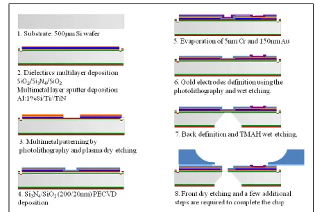
4.2 SENSOR MICROFABRICATION:SOI-MEMSCANTILEVERS ... 55
4.3 MICROCANTILEVER MATERIAL CHARACTERIZATION:GOLD LAYER ANALYSIS ... 57
4.3.2 Second Improvement: Ar Plasma Treatment ... 62
4.4 CANTILEVER FUNCTIONALIZATION ... 63
4.4.1 Evaluation of Spotting Technique Feasibility and Microcantilever Mechanical Resistance: Phosphate Buffer Deposition ... 64
4.4.2 Avoiding Contaminations: Fluorescein Deposition ... 68
4.5 CONCLUSIONS ... 69
CHAPTER 5 ... 71
5 CONCLUSIONS ... 71
5.1 LAB-ON-CELL RESULTS DISCUSSION AND FUTURE PERSPECTIVES ... 71
5.1.1 Electroporation Protocol Optimization ... 71
5.1.2 Electroporation Platform Improvements: Controlled Transfectants Delivery and Electrodes Functionalization ... 73
5.1.2.1 Microfluidics Module Optimization ... 74
5.1.2.2 Ns-TiO2 Film Effects on the Electroporation Protocol ... 74
5.1.3 Cell Entrapment and Internal Reference Electrodes ... 76
5.1.4 Different Cells and New Applications ... 77
5.2 CANTILEVER-BASED SENSORS RESULTS:DISCUSSION AND FUTURE PERSPECTIVES ... 79
5.2.1 Further Improvements of the Au Immobilization Layer: Cantilevers Cleaning ... 79
5.2.2 Real Usage of Microcantilever Arrays for Autoimmune Diseases Diagnostics: Biological Protocols and Procedures ... 80
5.2.2.1 DNA Probes Synthesis ... 80
5.2.2.2 DNA Grafting Density and Hybridization Efficiency ... 81
5.2.2.3 DNA Probes Accessibility Enhancement: MCH Incubation ... 84
5.2.2.4 Cantilever Biofunctionalization ... 84
5.2.2.5 Sensitivity and Response Estimation: DNA Target Hybridization ... 85
5.2.3 Cantilever-based Sensors Future Applications ... 87
ACKNOWLEDGMENTS ... 89
BIBLIOGRAPHY ... 91
APPENDIX A ... 111
APPENDIX B ... 115
Chapter 1
1
Introduction
1.1 The Context: Gene Analysis in the “-Omic” Era
The “-Omic” era and in particular the related genome sequencing have strongly increased the scientific interest towards gene analysis. A deeper understanding of gene function by
means of efficient cell transfection and a rapid identification of DNA mutations are in fact
more and more required in most of the biotechnological fields, from the study of
eu-karyotic gene regulation and expression in general to Single Nucleotide Polymorphisms
(SNPs) detection for diagnosis purposes.
Nowadays, different chemical and physical transfection techniques are used to deliver
nu-cleic acids (or other molecules of interest) into cells. Among the physical methods, bulk
electroporation lacks the spatio-temporal control over the process: it does not allow to
se-lect single or specific groups of cells (desirable requirement especially in highly
heteroge-neous tissues) and to monitor the transfection result in real-time. Moreover, a good
bio-compatibility and the possibility to perform multiple tests on the same chip represent
necessary requirements, especially in perspective of high-throughput screening.
On the other hand, gene analysis at sequence level needs portability, automation, reduction
of sample and reagent volumes, and the possibility, starting from a crude sample (whole
blood or saliva), to provide a genetic profile without labelling procedures.
In order to comply these demands and especially the request of high-throughput in-vitro
screening with spatio-temporal control over the process and fast label-free gene analysis,
alternative microscale approaches are increasingly required. In this context,
Micro-ElectroMechanical Systems (MEMSs) are emerging as alternative miniaturized and
port-able instrumentation for biomedical applications providing high sensitivity with low
1.2 Thesis Content and Innovative Aspects
On this subject, the thesis deals with two different tools for gene analysis: a Lab-on-Cell
and cantilever-based sensors for in-vitro cell transfection and SNPs detection, respec-tively:
(1)Lab-on-cell: integrated platform for the electroporation of cells grown in adhesion.
This research activity has been described from the choice of the microfabrication materials
suitable for the cell line culture to the real electroporation results, representing the most
substantial experimental part. This activity mainly presents the improvements of an
elec-troporation system for cells grown in adhesion [Vassanelli 2008] comprising multiple cell
compartments, underlying microfluidics, and patterning of the electrode active areas with
nanostructured titanium dioxide (ns-TiO2). Multiple cell compartments and underlying mi-crofluidics make possible the delivery of different transfectants solutions into specific
ar-eas of the same cell population, while the surface functionalization improves cell adhesion,
specifically where the voltage is applied to adherent cells. Thus, the demand of
high-throughput systems for in-vitro cell assays with good biaffinity properties has been satis-fied from a technological point of view and experimentally demonstrated by the obtained
successful gene tranfection. Both biological and physical factors have been taken into
ac-count for the optimization of the experiments. Further technological and experimental
im-provements have been discussed in conclusions.
(2)Cantilever-based sensors: detection module aimed at the integration in a
Lab-on-Chip (LOC) system for early diagnosis and screening of autoimmune disorders
based on typing of Human Leukocyte Antigens (HLAs).
Nowadays, microcantilever-based sensors feasibility for DNA detection has been
demon-strated. However, they are not consolidated for diagnosis purpose. Moreover, less attention
is given to the surface analysis and functionalization procedure. As for the previous topic,
surface holds a key role. The upper layer of the microcantilevers has been deeply analyzed.
Technical changes and cleaning procedures have been chosen in order to optimize it and
also the sample deposition procedure has been assessed. However, since this research
and a real usage of the array for SNPs detection, biological protocols and procedures have
been proposed and discussed in conclusions.
1.3 Structure of the Thesis
This thesis begins with the description of the state of the art related to gene analysis in Chapter 2. “State of the Art”. In particular, this Chapter is divided into two sections in
or-der to deepen different approaches for gene study: Cell Transfection (Section 2.1) and
Gene Sequence Analysis for Diagnostics (Section 2.2). Starting from traditional techniques employed to deliver genes into mammalian cells (viral-mediated processes, chemical,
me-chanical and physical approaches) (Paragraph 2.1.1), the attention is focused on electropo-ration. Some theory about pore formation and resealing is introduced in Paragraph 2.1.1.1. Then, in Paragraph 2.1.1.2 bulk electroporation is compared with single-cell electropora-tion. In this context, the emerging role of probes and microsystems is highlighted by
pre-senting an overview of the main advances achieved in this field, with particular attention
towards microdevices for both suspended and adherent cell electroporation (Paragraph 2.1.1.3). The significant role of materials bioaffinity and the related phenotypic behaviour consequent to cell-substrate interaction are discussed in Paragraph 2.1.2. Finally, Section 2.1 closes with the main current requirements in perspective of real high-throughput cell
in-vitro screenings and the thesis contribution in this direction (Paragraph 2.1.3). On the other hand, Section 2.2 regards, as anticipated, gene study at sequence level. It introduces LOCs emphasizing the need of label-free DNA detection. Paragraph 2.2.1 is devoted to label-free systems, in particular microcantilever-based sensors. Their two different
work-ing modes (static and dynamic) are here described, together with possible read-out systems
whose suitability for in liquid DNA detection is discussed. As in the previous Section, also
this one ends with moving beyond the state of the art for real application of
microcantile-vers in diagnostics. The importance of surface and functionalization procedure study,
dis-cussed in this thesis, is here anticipated (Paragraph 2.2.2).
Chapter 3. “Lab-on-Cell for Gene Transfection” is devoted to the first research activity
concerning an integrated platform for adherent cell electroporation. The choice of different
Microplasma Cluster Source (PMCS) technique employed for their functionalization with
ns-TiO2 is explained in Paragraph 3.1.2 as well as the deposited film characterization and related features. Then, a deep investigation of the substrates surface chemical composition
(Paragraph 3.1.3) precedes the real bioaffinity experiments carried out to define both cell viability and morphology on the materials (Paragraph 3.1.4). The schematic representation explaining the working principle and structure of the proposed system is shown in Para-graph 3.2 which is followed by the real development steps of the device: electroporation module (Paragraph 3.3) divided into the MicroElectrode Array (MEA) microfabrication (Paragraph 3.3.1) and procedure for electrodes functionalization with ns-TiO2 (Paragraph
3.3.2); microfluidics development and final packaging (Paragraph 3.4) with the relative microfluidic structure testing (Paragraph 3.4.1). Section 3.5 reports the experimental method for cell electroporation. It includes the description of the electroporation set-up
(Paragraph 3.5.1) and the choice of biological and physical factors suitable for the elec-troporation protocols (Paragraph 3.5.2). The real functional characterization of the devices represented by the biological tests is discussed in Section 3.6 showing the electroporation results with a preliminary value of electroporation efficiency calculated after gene
transfec-tion (Paragraph 3.6.1). Finally, this Chapter ends with the conclusions summarizing all the activities performed and the obtained results (Paragraph 3.7).
Chapter 4. “Cantilever-based Sensors for Gene Analysis”is devoted the second research
topic focused on a DNA detection module to be integrated, in future, into a LOC system.
After an introduction about the general subject, the design of the microcantilevers is
shortly described (Paragraph 4.1), whereas in Paragraph 4.2 the main microfabrication steps for the structures realization are summarized. Most part of this research activity is
aimed at the characterization of the Au immobilization layer of the microcantilevers, as
de-scribed in Section 4.3: after the first AFM and XPS analysis demonstrating non-uniformity and low content of Au, technical changes and a cleaning procedure are proposed as
im-provements (Paragraph 4.3.1 and 4.3.2). Besides the surface analysis, Chapter 4 reports the study of the functionalization procedure (Section 4.4). More precisely, after an intro-duction on functionalization procedures, this section is divided into Paragraph 4.4.1 and
Paragraph 4.4.2 which describe the deposition of phosphate buffer and fluorescein on the microfabricated cantilever arrays, respectively. Also this Chapter reports, at the end, the
In Chapter 5 “Conclusions” main activities and results are reported and discussed. In
par-ticular, similarly to Chapter 2, this final part of the thesis is divided into two sections. The first one (Section 5.1) reports the results concerning the Lab-on-Cell platform; the second one those regarding the cantilever-based array sensors (Section 5.2). More precisely, the first part is focused on the electroporation protocol optimization (Paragraph 5.1.1) and on the improvements of the platform itself (Paragraph 5.1.2). The possibility to entrap the cells and to have internal reference electrodes is also discussed in Paragraph 5.1.3. New applications of the Lab-on-Cell are suggested in Paragraph 5.1.4. On the other hand, in the
Section 5.2 the problem of having a low content of Au and C contamination is discussed in order to find out possible solutions (Paragraph 5.2.1). Finally, starting from literature, the steps for the real usage of the proposed detection module in diagnostics are listed giving
suggestions regarding biological protocols and procedures (Paragraph 5.2.2), from the sensitive layer generation to the DNA target hybridization and response evaluation. Future
applications are cited in Paragraph 5.2.3.
Chapter 2
2
State of the Art
As introduced in Chapter 1. Introduction, thanks to the completion of the whole human genome sequencing, functional genomics and proteomics tools have recently gained
sig-nificant attention. In fact, the interest towards gene analysis is increasing at different levels
and especially aimed at study (1) function by delivering genes into cells and observing
their relative expression; (2) sequence in order to detect DNA mutations for diagnosis
pur-poses. The following sections (2.1. Cell Transfection and 2.2. Gene Sequence Analysis for Diagnostics) summarize the main state of the art advances in both the analysis fields.
2.1 Cell Transfection
At present, it is well known that the plasma membrane represents the cell dynamic and
flexible structural component mainly acting as selective barrier against molecules crossing
[Alberts 2000]. It has been broadly studied in order to develop an efficient transfection
method. The word transfection refers to exogenous DNA molecules transfer into receiving cells. Once transfected, DNA is generally maintained in the cell cytoplasm for two-three
days. During this period, foreign genes undergo many regulative pathways which control
the chromosomal material expression of the host cell. Subsequently, dilution and
degrada-tion phenomena cause the DNA loss in most cases. In fact, transient or stable transfecdegrada-tions
can be distinguished depending on the exogenous DNA integration or not into own
chro-mosomes.
2.1.1 Mammalian Cell Transfection Techniques
In general, gene delivery into mammalian cells is inefficient per se, because it needs an
cells at the end of the experiment. For this reason, available cell lines able to continuously
grow in culture can be employed for the routine assessment of new transfection
proce-dures. An ideal transfection technique should ensure the following characteristics:
1. High transfection efficiency;
2. Low toxicity;
3. Reproducibility of the experiments in-vitro and in-vivo.
Nowadays, different techniques are used to deliver exogenous DNA into cells complying
with the above requirements with peculiar advantages and showing specific drawbacks. In
general terms, these techniques can be divided into four categories: (1) viral-mediated
processes and (2) chemical, (3) mechanical or (4) physical approaches. The first group
in-volves biological vectors such as adenoviruses and retroviruses in a process corresponding
to cell infection [Anson 2004]. Preparation difficulty, immunity rejection and viral toxicity
represent the main disadvantages [Chuah 2003]. Among the second category, chemical
re-agents exploit the DNA co-precipitation with calcium phosphate [Graham 1973] or the
complex generation between DNA and a variety of polycations in polyfection (e.g.
DEAE-dextran [McCutchan 1968]) or cationic lipids in lipofection [Felgner 1987]. They are not
very expensive and the experimental procedure is simplified. Nevertheless, they do not
guarantee a good transfection efficiency and they are prone to a certain variability. As a
matter of fact, the DNA transfer is not direct, thus limiting the internalization and
expres-sion because of essential intermediate steps (i.e. cell attachment, endocytosis, complex
dis-sociation). On the contrary, direct transfection techniques are represented by mechanical
(microinjection, particle bombardment - gene gun) and physical (sonoporation, laser irra-diation, electroporation) approaches. Mehier-Humbert et al. have highlighted their working
principles, employed materials, advantages and limitations providing a complete summary
according to the following performance criteria: transfection efficiency, toxicity, targeting
and practicality [Mehier-Humbert 2005]. Microinjection represents the most direct method
allowing the selective DNA delivery into specific cell compartments (e.g. cytoplasm or
nu-cleus) by employing a glass needle controlled by a micromanipulator with the highest
effi-ciency (up to 100%). However, it is too laborious. Moreover, the high cost, the application
difficulty and the possibility to transfect only one cell at a time make it impractical for
DNA per dose are accelerated to the sample. Thus, the transfection can indiscriminately
occur in each cell compartment, interfering whether with cell structure or function. In
gen-eral, physical approaches are well tolerated. By applying ultrasounds, sonoporation forms
small transient pores mainly due to acoustic cavitation mechanism and improving cell
permeability. The technique can be employed for the transfection of different tissues. In
la-ser irradiation, the thermal effect changes the cell permeability in the lala-ser impact region.
This technique suffers from appropriate know-how requirement, expensive and
cumber-some laser sources.
Among the physical methods, electroporation, also called electropermeabilization,
represents one of the most employed transfection techniques. The traditional bulk
electroporation generates transient nanopores in the plasma membrane of suspended cells
by applying a homogenous electric field between two large electrodes at a distance in the
range from mm to cm [Weaver 1996, Ho 1996].
2.1.1.1Pore Formation and Resealing
Different models try to find the right explanation of the electroporation mechanism. Lipid
membrane instability could be due to macroscopic factors, such as thinning and
compression, or to the transition from hydrophobic to hydrophilic pores, more stable above
a critical pore radius [Weaver 1993, Neumann 1999].
Nevertheless, there is a commonly accepted concept: nanoscale pores form as a
consequence of the transmembrane potential increase which follows the application of a
high voltage. More precisely, under an external electric field both the natural resting potential (ΔΨ0, typically about -70 mV) and the induced membrane potential (ΔΨE) contribute to the potential difference across the membrane (ΔΨm= ΔΨ0+ ΔΨE). In this context, electroporation occurs when ΔΨm exceeds a critical threshold value (ΔΨc).
Experimental procedures have determined this value to be in the range of 200 mV–1V and
the relative critical electric field Ep from 100 Vcm-1 up to 10 kVcm-1 depending on the cell type [Neumann 1972, Zimmermann 1974, Teissie 1993, Weaver 1993, Rols 2006].
The membrane permeabilization initially occurs at the cell pole facing the positive
where the capacitance of the membrane is first exceeded when an external field is applied.
The area of the membrane which is permeabilized depends on the pulse amplitude,
whereas the degree of permeabilization can be controlled by pulse duration and pulse
number [Gabriel 1997].
Nowadays, five steps are considered to be involved in pore generation mechanism: (1)
Pores induction (< 1µs, ns range [Beebe 2003, Vernier 2006]) due to the application of the
external electric field; (2) Expansion (µs-ms range) during which the pore density
in-creases depending on the pulse duration. The higher the permeability, the higher the cell
conductivity; (3) Stabilization or membrane reorganization. It occurs when the electric
field decreases; (4) Resealing (from seconds to minutes). In absence of field the
imperme-ability of cells is spontaneously recovered. Nevertheless, physical settings sensitively
in-fluence the electroporation result. Pores can be distinguished in transient
(reversible/self-repairing) or not (irreversible) depending on parameters of external electric field,
charac-teristics of the electroporation medium (conductivity) and of the cell (electric properties
and shape) that is exposed to the electric field [Canatella 2001]. If these parameters are not
suitable and accurately evaluated, irreversible electroporation takes place and cell death is
inevitable.
2.1.1.2Bulk/Batch Electroporation vs Single-Cell Electroporation
As for most of the traditional transfection procedures, one of the main limitations of bulk
electroporation is the lack of spatio-temporal control over the process: it does not allow to
select single cells (desirable requirement especially in highly heterogeneous tissues and
primary cultures), and to monitor the transfection result in real-time. To circumvent these
disadvantages, alternative microscale approaches are increasingly required. Single cell
electroporation (SCEP) represents a promising tool in biochemical research, where
ma-nipulation and analysis at single cell level are required. Unlike bulk electroporation
involv-ing a homogeneous electric field applied to a whole cell population, SCEP is characterized
by two possible working principles:
(i) Inhomogeneous electric fields focused near selected single cells;
(ii) Single cells isolation from their population in order to impose the electric pulses
Moreover, the variety of outcomes typical of the bulk electroporation is replaced by the
possibility to optimize the electroporation protocols (generally using pulses in the order of
few volts) by directly looking into the single responses.
In the last years, different research groups have extensively reviewed the emerging SCEP
techniques. A complete guidance comes from Wang et al. [Wang 2010]. Olofsson et al.
have thoroughly discussed the multiplicity of systems employed to perform SCEP
[Olofsson 2003]. Microfluidic single cell analysis has been also deepened with a brief
in-troduction to SCEP chips [Chao 2008]. Moreover, Fox et al. have discussed
electropora-tion by using microfluidic devices [Fox 2006].
2.1.1.3Microfabricated Devices for the Electroporation of Target Cells
Currently, different methods are able to perform in-situ and in-vivo electroporation. Solid microelectrodes [Lundqvist 1998], modified Atomic Force Microscopy (AFM) silicon tips
[Nawarathna 2008], electrodes filled with transfer material [Bestman 2006], Electrolyte
Filled Capillaries (EFC) [Nolkrantz 2001, Agarwal 2009, Wang 2009] and micropipettes
[Haas 2001 and Hewapathirane 2008 optimized the electroporation method for Xenopus laevis Tadpodes, Rae 2002, Rathenberg 2003, Pakhomov 2007, Uesaka 2008, Barker 2009] (also in combination with microelectrodes [Karlsson 2000, Ryttsen 2000, Alberg
2001, Tanaka 2009]) are employed as probes claiming a great spatio-temporal control over
cell transfection.
Nevertheless, microfabricated devices are strongly emerging in this field for both
manipulating selected cells in suspension or in adhesion.
Some of the most significant examples of microfabricated devices aimed at suspended cell
electroporation are here reported. In 2001, Y. Huang and B. Rubinsky developed the first
chip based on single cell trapping in microholes by pressure difference (between the top
and bottom microfluidic chambers of a three-layered device) and electroporation by
constricted field [Huang 2001]. In order to achieve high efficiency of gene transfection an
improved device characterized by microfluidic channels was proposed by the same
research group in order to handle cells in a flow-through manner [Huang 2003].
Kurosava et al. in a more recent work demonstrating its application for the measurement of
cell response to external stimuli [Kurosawa 2006]. In the integrated PDMS multiple patch
clamp array developed by Khine et al. cells were laterally immobilized and electroporated
at the end of microchannels [Khine 2005, Khine 2007, Ionescu-Zanetti 2008]. Channels
and microholes are the main components of another successful example: gene transfer was
performed in stem cells by employing a silicon glass device characterized by two channels
connected by microholes acting as trapping sites [Valero 2008]. Single-cell electroporation
by employing a planar micropore chip in combination with 2-D scanning vibrating
electrode technology was also reported [Haque 2009].
Instead of entrapping cells at microholes or at microchannels opening smaller than the cells
(as described up till now), in other systems electroporation occurs in channels or confined
regions larger than the cells. A droplet-based microfluidic device was described: droplets
containing cells flowed through two microelectrodes on the substrate [Zhan 2009]. The
amplification of the electric field in the narrow region of a microchannel was exploited by
Wang et al. for both lysis and electroporation [Wang 2006, Wang 2008]. Others performed
cell lysis by electroporation, for example using 3D electrodes [Lu 2006] and a
dielectrophoresis (DEP)-based chip [Ramadan 2006]. Ti/Pt electrodes deposited on a glass
microscope slide were used to dielectrophoretically move and electroporate monocytes
[MacQueen 2008]. Moreover, micropulsed radio-frequency was also employed in a chip
allowing a 3D electric field distribution [He 2007]. Finally, among the most recent works,
three groups have given great contributions in the microengineering field. Geng et al.
improved the flow-through Wang’s group electroporation chip described before with five
narrow sections for the transfection of a large amount of cells [Geng 2010]. Andresen et al.
proposed an injection molded chip comprising conducting polymer electrodes [Andresen
2010]. Moreover, both cell arraying and electroporation were carried out by Mottet et el. in
a transparent LOC including 3D microfluidics and thick electrodes [Mottet 2010].
However, since most part of human body cells grows in adhesion and especially in case of
mammalian cells there is an increasing cell line usage as model system similar to the in-vivo one, the development of microsystems well-suited for adherent cells electroporation is gaining more and more attention. A variety of mechanisms have been published. One of
the first and easiest is represented by a defined cell culture cavity and thin-film electrodes
was enhanced by employing an attracting field for DNA plasmids increasing their
concen-tration close to the adherent cells [Jen 2004]. A porous membrane-based electroporation
device was reported: cells were cultivated on a microporous alumina membrane and below
it a polydimethylsiloxane (PDMS) film characterized by microholes was added. The
elec-tric field generated between two electrodes (one positioned above the cells and the other
below the PDMS film) was concentrated in the areas defined by the holes allowing the
se-lective electroporation of cells grown in those regions [Ishibashi 2007]. Alternatively,
Vas-sanelli et al. proposed an array of planar cell-size microelectrodes (each one independently
addressable) microfabricated in FBK facilities, allowing cells to be cultivated, randomly
adhere and be selectively transfected [Vassanelli 2008]. Chang et al. employed pairs of
thick and closely opposed microelectrodes to focus the horizontal electric field on targets
(individual neuronal axons as reported example) in between them [Chang 2009]. PDMS
was used also by Kim et al. for the development of a multi-channel electroporation chip
able to generate multiple electric field gradients on the same device depending on the
channel length were cells were cultivated. The high-throughput of the system (up to five
channels) was exploited to simultaneously and easily analyze the cell response to
increas-ing electric fields [Kim 2007]. Among innovative and extremely recent works, Koester et
al. reported the new local micro invasive needle electroporation (LOMINE) carried out on
the PoreGenic® chip consisting of DEP and needle electrodes array [Koester 2010]. Three-dimensional electrodes were employed also by Braeken et al. Their sub-cellular
dimen-sions allowed to locally stimulate cardiomiocytes and single neurons in-vitro [Braeken 2009, Braeken 2010].
2.1.2 Cell-Substrate Interaction and Bioaffinity Requirements in Microsystems Field
Bioaffinity represents a fundamental parameter for the appropriate choice of the most
suit-able materials to develop BioMEMS-based devices aimed at in-vitro cell assays. The cell capability to recognize and interact with a substrate represents the first essential step
allow-ing cell proliferation, migration and differentiation. In general tissue architecture and
morphogenesis, cell adhesion follows a specific protein-mediated mechanism. These
transmit the signal from the cell surface to the thick network of cytoskeletal filaments that
make up the cell scaffold. In particular, the interaction between cell surface integrin
recep-tors and ExtraCellular Matrix (ECM) adhesion molecules generates a signal cascade
fol-lowed by actin cytoskeleton reorganization and consequently the cell morphology change.
The cell, initially round-shape (integrin inactivated state), then becomes spread (integrine
activated state). This second morphological state represents an adhesion strengthening
which involves focal adhesion junctions assembly and forces along the basal cell surface
[Gumbiner 1996]. Also the complex nature of the interaction between cells and
biomate-rials has been studied and reviewed, giving a deep explanation about the molecular basis of
this mechanism by means of transcriptomic and proteomic tools. The ECM composition is
influenced by the substrate surface features. This aspect causes different integrins
activa-tion patterns and spatial arrangement, then reflected in the cell phenotype [Gallagher
2006].
In fact, it is well known that cell phenotypic behaviour and response strongly depend on
the nature of the employed material. Its properties (i.e. roughness, chemical composition,
wettability, surface functionalization or patterning, topographical features) cause specific
cell response due to the direct contact of the cell culture with the substrate and altered
phe-notypes can also reveal altered cell functions, due for example to an incompatible substrate
[Dewez 1999, Lampin 1997, Ito 1999, Berry 2004]. More specifically, the surface
charac-teristics affect the serum protein adsorption layer which represents the real cell-substrate
interface [Lynch 2007]. Cell-material interaction has been also studied by using
microfab-ricated substrates [Petronis 2003, Digabel 2010].
As a consequence, microfabrication technology applied to cell culture is a topic constantly
under study in order to develop enhanced system aimed at performing assays on cells
grown in suitable conditions similar to the in-vivo microenvironment [Park 2003, Bha-driraju 2002].
In particular, the interest towards surface modifications for the development of biomimetic
substrates aimed at cell culture and tissue engineering is more and more increasing [Healy
1999, Lan 2005]. Moreover, since in-vivo cells are surrounded by nanoscale topography, there is a strong attention towards nanotechnology for the development of biocompatible
microsystems and also implantable biomedical devices [Sniadecki 2006, Polizu 2006]. In
fact, nanoscale features are often integrated in order to influence cell adhesion and shape
2.1.3 Moving beyond the State of the Art
A good biocompatibility and the possibility to perform multiple tests on the same chip
rep-resent necessary requirements, especially in perspective of high-throughput screening.
Be-yond the state of the art, the possibility to strictly control the delivery of different
transfec-tant solutions toward specific areas of the same cell population represents one of the main
goal. In fact, current methods usually allow the delivery of only one transfectant at a time.
In this context, microfluidics is becoming an important feature in microdevices for cell
analysis and system biology in general [Yi 2006, Szita 2010]. Beyond the multi-channel
microsystem proposed by Kim et al. able to test different electrical protocols on the same
chip (Paragraph 2.1.1.3), some other recent advances have been introduced in this field. From a structural point of view, Wang et al. developed a microfluidic cell array suitable for
high-throughput cell screening. It is characterized by individually addressable chambers
where different cells groups can be cultivated and different reagents can be delivered.
However, they do not perform electroporation or gene transfection [Wang 2008]. Thus, the
possibility to electroporate different cell groups with different transfectants represents a
challenge for the development of real high-throughput Lab-on-Cell platforms.
In this context, the following thesis deals with a Lab-on-Cell for the electroporation of
ad-herent cells. It is characterized by multiwells for cell confinement, a microfluidic structure
based on independent channels and ns-TiO2 functionalized electrodes for the improvement of cell adhesion specifically where the voltage is applied. Chapter 3. Lab-on-Cell for Gene Transfection is dedicated to this integrated platform.
2.2 Gene Sequence Analysis for Diagnostics
In the last decade the development of biological analysis systems has raised a great interest
within the scientific community. Microsystems technologies are able to comply with the
requirement of reduction of time, costs and increased sensitivity, by means of micro-Total
Analysis Systems (μ-TAS). These integrated, miniaturized devices are capable to carry out
different steps of an analysis technique all on the same chip [Lee 2004, West 2008]. In
treatment, amplify the DNA, and detect specific DNA sequences (oligonucleotides) on the
same device [Anderson 2000, Campas 2004, Easley 2006]. Its main advantages are (1)
im-proved performances related to higher sensitivity, throughput and automation of the
analy-sis; (2) portability; (3) reduced costs because of minute sample and reagents volume
con-sumption (microlitres); (4) integration of many analysis steps which allows, starting from a
crude sample (whole blood or saliva), to rapidly provide a genetic profile. Among possible
applications, the key one is the Point-of-Care (POC) diagnostics which opens up new
per-spectives in the field of personalized medicine and treatment. In particular, BioMEMS,
with the integration of microelectronics and nanobiotechnology, are enabling the
realiza-tion of biosensors able to perform sample handling and to detect specific bioaffinity
reac-tions (DNA/DNA, antigen/antibody, enzyme/receptor) by means of suitable
functionaliza-tion procedures (covalent binding, matrix entrapment, cross-linking and adsorpfunctionaliza-tion)
[Bashir 2004].
In literature, several research works devoted to the development of integrated LOC devices
for DNA analysis have been presented. For instance Dobson et al. have reviewed the state
of the art with respect to commercial or semi-commercial systems for POC applications
[Dobson 2007]. In particular, it can be evinced that the first generation of LOCs for
mo-lecular diagnostics at POC level is mainly based on (quantitative-fluorescent) Real Time
Polymerase Chain Reaction (RT-PCR) [Zhang 2007]. This method allows also multiple
de-tections per assay by means of the so-called multiplex PCR [Edwards 1994]. PCR based
systems are usually employed for pathogen detection by identifying one or few target
se-quences [Dobson 2007, Malic 2007]. However, also real array technologies are available in
this context, allowing to detect a large number of SNPs or DNA sequences thanks to their
multiplexed structure. Among the most employed techniques, DNA microarray technology
[Pritchard 2008] is characterized by high-throughput capabilities, but needs, like RT-PCR,
sample labelling procedures.
2.2.1 Micro-ElectroMechanical Systems (MEMSs) for DNA Hybridization Detec-tion: Cantilever-based Arrays
The detection of a specific DNA sequence can be performed by exploiting the DNA
DNA (ss-DNA) binds its complementary by means of base pairing (adenine with thymine
and guanine with cytosine). Thanks to its simplicity it is more commonly used than the
di-rect sequencing of DNA. Moreover, the hybridization process is very efficient and specific.
The working principle is the following: if two ss-DNAs perfectly match they can bind each
other, otherwise the hybridization does not completely occur. Thus, this reaction can be
sensitive also to small variations such as a single base mutation between two strands,
al-lowing the detection of SNPs often responsible for genetic diseases.
In this context, a great interest is currently given to the development of label-free detection
systems: electrochemical [Drummond 2003], waveguide [Bliss 2007] and Surface Plasmon
Resonance (SPR)-based [Boozer 2006, Abdulhaim 2008] methods. Among the
electro-chemical systems, Ion Sensitive Field Effect Transistors (ISFETs) [Fritz 2002, Kim 2004,
Ingebrandt 2007] and potentiometric systems [Numnuam 2008] have been reported in
lit-erature. In general, electrochemical methods are characterized by high sensitivity and
SNPs detection capability. On the other hand, devices based on SPR have been also used to
detect DNA hybridization with high sensitivity results. On the market some laboratory
in-strumentations are available, like the Biacore S51 [Myszka 2004]. However, SPR is
diffi-cult to implement in miniaturized portable systems because of the measurement principle
requiring the precise alignment for the optical excitation and detection parts [Abdulhaim
2008]. Other approaches encompass optical biosensor Microsystems; they are based on the
integration of highly sensitive Mach-Zehnder interferometer devices [Sepúlveda 2006].
Nowadays, among a large number of MEMS-based devices developed in order to detect
the DNA hybridization event, most of them are constituted by cantilever array sensors
[Sepaniak 2002, Ziegler 2004]. Microcantilevers are typically silicon suspended bars (less than 1μm thick, from tens to hundred of μm long and some tens of μm wide, thus 0.01 the
size of their macroscopic counterparts Quartz Crystal Microbalances - QCM [Wang 1997])
able to detect the interaction between a specific functional layer and the analyte of interest.
Depending on the functional layer, they are suitable for chemical or biological sensing. In
particular, if the cantilever surface is properly functionalized with a specific probe, able to
selectively bind a particular target molecule, the device can behave as a chemical or
bio-chemical sensor. Different sensitive films are available, ranging from polymeric coatings
(polyetherurethane - PEUT, phthalocyanines, etc.) for gas sensing applications to DNA
oligonucleotide probes for detection of specific gene sequences. In fact, if the functional
spe-cific oligonucleotide sequence, present in a unknown sample, can be easily detected. In
case of complementary target, the following hybridization induces a differential stress
be-tween the top and the bottom surfaces of the cantilever, driving the deflection of the beam
[Fritz 2000]. Cantilever-based sensors are extremely versatile; they can be operated in air,
vacuum, or liquid. They can be mass-produced by means of micromachining as
miniatur-ized sensor arrays increasing their potentiality as low cost devices with high performances,
high level of integration and portability [Raiteri 2001, Baller 2000, Rasmussen 2003,
Datskos 2004]. In spite of the large availability of cantilevers for AFM, silicon, silicon
ox-ide, and nitride cantilevers for biosensing are rarely commercially available (e.g.
Can-tiChip8 array of eight nanomechanical cantilevers with integrated electrical read-out
[Can-tion]). Cantilevers are present with different shapes, dimensions, and force sensitivities
capable of measuring in the 10–11 N range at the levels of single molecular interactions.
The adsorption of target molecules on the microcantilever sensitive layer induces both an
increase of cantilever mass and the generation of superficial stress. Therefore, two different
working modes can be used for cantilever-based measurements: the dynamic and the static
mode, respectively [Datskos 2004, Ziegler 2004, Lang 2005]. The former exploits the
resonance phenomenon, the latter the deflection. However, both deal with beam bending
and thus sometimes they can be contemporaneously exploited.
In dynamic mode a change in resonance frequency due to analytes adsorption is measured.
In fact, the shift in the cantilever resonance frequency (Δf=f0-f1 (Hz)) reveals the mass
variations (with respect to the reference condition) due to the binding of target molecules (Δf Δm). The beam vibrates at its Eigen-frequencies generating a stress distribution and
deformation typical for each resonance mode. In the first mode, the resonance frequency
can be estimated by the simplified models reported in literature [Hansen 2001, Raiteri
2001, Datskos 2004, Ziegler 2004], where the structure is considered as a simple
spring-mass oscillator. The spring-mass variation with respect to the initial spring-mass m0 can be expressed as follows: ] 1 1 [ 4 2 0 2 1 2 f f k
m
where k is the elastic constant
3 3 3 4 3 L EWt L EI
with E that is the Young’s modulus of Si, and W, t and L the width, thickness and length of the beam, respectively.
The resonance frequency f0 for the first resonance mode is:
3 * 3 * 0
4
2
1
2
1
L
m
EWt
m
k
f
where m* is the effective mass that can be related to the mass of the beam, m, through the relation m* = nm, where n is a dimensionless geometric parameter equal to 0.24 for a rec-tangular cantilever.
Therefore, both m* and k are related to physical properties and geometry of the beam. Higher sensitivities can be achieved from thin, low-density devices.
Another important parameter is the quality factor Q which depends on the viscous damping
of the cantilever vibration. The detection of the resonance frequency and the amplitude of
the read-out for a given actuation intensity are strictly related to the quality factor, which
can be estimated by Q=f0/Δf whose value increases when the measurement is carried out in
vacuum. Q depends on the corrected cantilever mass, on the damping and on the natural
circular frequency: b m Q * 0
where b is the drag coefficient for the beam motion and in first approximation it is propor-tional to the beam width and fluid viscosity. The efficiency of the resonance method is
strongly affected in liquid environment, making the deflection mode more suitable for such
applications. However, an improvement of the quality factor can be achieved by using a
feedback system for the actuation, where the signal detected from the cantilever is fed to
the actuator. This has been demonstrated to improve the read-out efficiency of orders of
magnitude [Vidic 2003], making this approach usable also in liquid phase, although
gener-ally deflection mode can provide better performances in liquid. Actuation can be
per-formed with several approaches, including integrated and discrete piezoelectric devices,
electrostatic and magnetic induction set-up [Vidic 2003, Rogers 2003].
In deflection mode, bending of the cantilever δ, due to the chemical-physical reactions
which specifically occur on one side of the beam, is measured. Nevertheless, the bending
is related not only to the reaction-induced stress, but also to physical properties and
3 2 12t E L
where ν is the Poisson’s ratio of the material and σ is the induced stress on the top side of the microcantilever.
Thin – low elastic modulus devices show best sensitivities in static mode, even if the
ther-mal vibration noise increases by reducing the structure stiffness [Butt 1995]. In fact,
com-pliant structures are preferred in deflection mode, while stiff and light structures are more
suitable for the resonance one. This aspect must be taken into account when selecting the
materials and technologies to realize a cantilever structure. Recently, polymeric beams
(with Young modulus orders of magnitude lower then Si-based materials such as
crystal-line Si, SiO2 and Si3N4) have been developed for static mode [Thaysen 2002, Calleja 2005, Johansson 2005]. Nevertheless, their stability in operative conditions should be
investi-gated. Moreover, polymer-based technologies are not easily integrated with standard
tech-nologies and CMOS read-out with respect to other approaches.
Among the techniques employed to detect the cantilever bending (optical, piezoelectric and
piezoresistive read-outs, electrostatic or electromagnetic based methods [Datskos 2004]),
the most commonly used are the optical and piezoresistive read-outs [Carrascosa 2006],
suitable for both the working modes.
In the optical read-out method it is possible to measure the absolute value of cantilever
bending by means of a photodetector sensitive to the optical deflection of an incident laser
beam. The need of a sophisticated alignment system for the optical beam makes this
ap-proach not really suitable in case of detection module with array architecture. The
piezosistive method needs a dc-biased Wheatstone bridge in order to measure the changes in
re-sistivity of the cantilever material due to surface stress variations. For LOC applications
where DNA-sensing properties are needed, the optical read-out is often employed because
of its high sensitivity. Nevertheless, this method shows several significant drawbacks such
as the possible beam refraction in liquid samples, high sensitivity to opacity and the
diffi-culty to assure the collimation of the laser with the beam. The piezoresistive read-out
re-veals to be more suitable for the development of portable devices, due to its easiness of
implementation into a microfabrication process [Mukhopadhyay 2005, Choundhury 2007].
Piezoresistivity is related to a carrier mobility change in semiconductors as a consequence
sens-ing events generatsens-ing surface stresses: resistors, diodes and field-effect transistors with in
general comparable sensitivities.
2.2.2 Moving beyond State of the Art
Nowadays, the feasibility of microcantilever-based DNA biosensors has been
demon-strated for DNA detection in general and also for single-base mismatch identification [Fritz
2000, Hansen 2001, McKendry 2002, Alvarez 2004, Mukhopadhyay 2005, Stachoviak
2006, Yang 2008]. However, even if the integration of an electronic interface realized with
a CMOS technology has been also proven [Verd 2005, Yu 2007, Yu 2008], this technique
is not still consolidated for real diagnosis purpose. In fact, a real LOC with an integrated
cantilever array is not yet available for this type of application. Moreover, the development
of high density arrays, comprising from ten to thousands of differently functionalized
can-tilevers, represents one of the most important challenges in genomics. In fact,
high-throughput platforms are becoming more and more requested in order to allow real-time,
fast and simultaneous detection of a variety of DNA sequences, especially polymorphisms
for diagnosis purpose. Compared to the current high-throughput DNA microarray
technol-ogy [Pritchard 2008], cantilevers arrays are a promising alternative, because they permit
the direct analysis of molecules without need of fluorescent labels. Since the labelling
pro-cedure is a compulsory step in almost all the routine tests, time consuming and very
expen-sive, the cantilever-based technology will improve the genetic analysis in terms of time and
cost effectiveness. The expected ultra-high sensitivity of the device (which can reduce or
even avoid the need of DNA amplification, thus simplifying the structure of a LOC
de-vice), and the label-free detection mechanism could give a high added value to a diagnosis
system.
However, apart from the intrinsic advantages coming from the development of
cantilever-based systems, in literature less attention is given to the study of important preliminary
phases such as the surface analysis and cantilever functionalization. For example,
Tabard-Cossa et al. reported the study of the effect of morphology, adhesion, cleanliness of the
sensitive layer on surface stress measurements [Tabard-Cossa 2007]. Also Desikan et al.
evaluated the effect of nanometric morphology on the stress sensing properties [Desikan
(immobiliza-tion of probes) on microcantilevers [Bietsch 2004]. For this reason, a deeper knowledge of
the immobilization layer (and how to optimize it) is still needed also in order to circumvent
difficulties during the practical application.
Regarding these aspects, the thesis deals with the analysis of the immobilization layer of
microcantilever arrays which will be integrated in a LOC for autoimmune diseases
diag-nostics. The necessity of further optimization and the functionalization procedure have
Chapter 3
3
Lab-on-Cell for Gene Transfection
3.1 Comparative Bioaffinity Studies for in-vitro Cell Assays on MEMS-based De-vices
In order to choose the optimal materials for the Lab-on-Cell microfabrication bioaffinity
studies were performed. Moreover, since there was an increasing attention toward
nanopar-ticle-assembled materials for the development of biocompatible devices (see Paragraph 2.1.2. Cell-Substrate Interaction and Bioaffinity Requirements in Microsystems Field), a comparative analysis was carried out to check cell growth and morphology differences also
on ns-TiO2 films.
3.1.1 Candidate Substrates for Bioaffinity Tests
Different candidate substrates were chosen among those most employed for the
develop-ment of MEMS-based devices [Maluf 2004, Beeby 2004] and deposited on Si wafers
where an oxide layer (300 nm) was previously grown as adhesion interface. Both
sub-strates and employed microfabrication technologies are listed in Table 3.1.
Table 3.1. Substrates and relative microfabrication technologies employed for bioaffinitystudy. Substrates Microfabrication technology
Ti (120 nm) Sputtering
Si
3N4 (100 nm) Plasma Enhanced Chemical Vapour Deposition (PECVD) SiO
2(18 nm) Plasma Enhanced Chemical Vapour Deposition (PECVD) Au (150 nm) Evaporation: electron beam deposition
More precisely, SiO2 was deposited over a 100 nm Si3N4 layer and an intermediate layer of Cr (5 nm) was used as adhesion promoter for Au and Pt layers. These two substrates were
also subjected to an hard bake (30 min, 190°C) in order to improve the metal adhesion.
Then, each wafer was treated with an oxygen plasma in order to remove organic
com-pounds. Finally, the wafers were cut by means of a dicing saw.
As shown in the schematic sketch (Figure 3.1), a comparison between the materials
re-ported in Table 3.1 (Zone 1), fabricated in FBK facilities, and ns-TiO2 film (Zone 2) was carried out by depositing the last one on approximately one half of each substrate, while
masking the other half. In Figure 3.2, two examples are presented.
Figure 3.1. General cross-section of the deposited materials.
Figure 3.2. (Left) Au and (Right) Ti substrates (20 mm x 20 mm) functionalized with ns-TiO2.
3.1.2 Cluster-assembled TiO2 Film Deposition and Characterization
TiO2 films were deposited by means of Supersonic Cluster Beam Deposition (SCBD) technique [Wegner 2006]. A Pulsed Microplasma Cluster Source (PMCS), developed by
IFN-CNR (Trento) was employed and the same research group carried out the deposition
This method is suitable for the assembly of nanostructured and nanocrystalline metal
ox-ides films in a Ultra High Vacuum (UHV) apparatus. The source, schematically shown in
Figure 3.3, is based on the expansion of a neutral gas in vacuum with a fixed percentage of
oxygen (He+O2 0.1%).
Figure 3.3. The Pulsed Microplasma Cluster Source (PMCS) employed for the substrate functionalization with ns-TiO2 (IFN-CNR, Trento).
The gas mixture goes through a pulsed valve into a small chamber, where directly flows on
two metal Ti electrodes. Between the electrodes a pulsed synchronized high voltage
dis-charge causes the seeding of the beam by clusters of Ti that, combining with O2, forms
nanoclusters of TiO2 of different shape and size. The distribution of clusters exits from the source forming a seeded beam that goes to hit the substrate in the deposition chamber
gen-erating a ballistic growth of clusters. The deposited film features strongly depend on the
set-up conditions (i.e. expansion parameters and discharge characteristics).
Besides the deposition, IFN-CNR (Trento) and CNR-Licryl Laboratory-CEMIF.CAL
(De-partment of Physics, University of Calabria) analyzed the obtained film. In detail, the
opti-cal, morphological and structural characterization of the TiO2 was carried out by means of Spectroscopic Ellipsometry (UVisel, Jobin Yvone) [Vedam 1998, Losurdo 2002,
Kamin-ska 2005], Scanning Electron Microscopy (SEM) [Goldstein 2003] and local micro-Raman
analysis [Ferraro 2003] by means of a microprobe set-up (Labram, Horiba-Jobin-Yvon),
respectively.
growth stages of the film (spectra not shown). Moreover, SEM technique gave information
about grain structure and relative dimension. Figure 3.4 shows the typical morphology of
the produced ns-TiO2 films.
Figure 3.4. (Left) SEM micrographs of one TiO2 sample grown by means of PMCS source; (Right) The high-resolution image shows the typical nanostructured morphology of the films with an average grain dimension of 10 nm (IFN-CNR, Trento).
The micrographs reveal that the assembling of clusters grows the film. At higher
magnifi-cation grains dimensions can be clearly assessed: the morphology of ns-TiO2 film is char-acterized by nano grains ranging from 8 to 20 nm in size, with the presence of distributed
larger clusters in the micron scale. This kind of morphology presumes also a high porosity
present in the films, confirming the result achieved with the data extracted by the
ellip-sometry where the films showed a porosity of about 50%.
CNR-LICRYL Laboratory - CEMIF.CAL (Department of Physics, University of Calabria)
performed a micro-Raman analysis on the larger clusters revealing a crystalline structure of
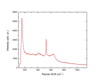
TiO2 mostly in the Anatase phase. In Figure 3.5, a typical micro-Raman spectrum of the larger micrometric grains of TiO2, showing a predominant Anatase phase.
In fact, the three Eg modes predicted for Anatase [Giarola 2010], a strong peak at 151 cm-1, a shoulder at about 200 cm-1 and a broad band at 633 cm-1, as well as one of the B1g mode at 409 cm-1 are clearly observable. The one-phonon peak of the c-Si substrate, occurring at
the 409 cm-1 Anatase mode. Finally, two–phonon scattering from Si substrate generates two weak and broad peaks at about 300 and 970 cm-1 in the observed spectrum. The large bandwidths of the modes and the frequency shifts with respect to the values commonly
re-ported in literature [Giarola 2010] could indicate small size crystal domains and strained
structures in the deposited TiO2.
Figure 3.5. Micro-Raman spectrum on a grain of TiO2 deposited on c-Si. Excitation source was the 633 nm line of He-Ne laser. A notch filter allowed the observation only above 150 cm-1 (CNR-LICRYL Laboratory , University of Calabria).
The deposition parameters were optimized in order to obtain the maximum of controlled
crystalline Anatase phase. More precisely, the crystalline structure was maximized by
set-ting 450 ms opening time and 1250 V discharge voltage.
3.1.3 X-ray Photoelectron Spectroscopy (XPS) Analysis of the Substrates
Before evaluating the substrates bioaffinity, a deep investigation about the surface nature
was necessary. In fact, as explained in Chapter 2 (Paragraph 2.1.2. Cell-Substrate Interac-tion and Bioaffinity Requirements in Microsystems Field), the phenotypic behaviour of cells strictly depends on material properties (i.e. hydrophobicity, charge, chemical
In this context, besides the SEM analysis which clearly revealed the nanometric structure
and porosity of the cluster assembled TiO2 films, the analysis of the substrates chemical composition represented another relevant step before the biological response assessment.
The atomic concentrations of TiO2 film and of the selected materials (Table 3.1) were de-termined by XPS [Barr 1994] (tilt 30°) analysis (Scienta ESCA 200 instrument equipped
with a hemispherical analyzer and a monochromatic Al KR (1486.6 eV) X-ray source in
transmission mode). A representative chemical composition of all analyzed ns-TiO2 films deposited on the different substrates is reported in Table 3.2.
Table 3.2. Atomic concentration of TiO2 film deposited by PMCS as determined by XPS surface analysis (tilt 30°), expressed in percentage (MiNALab-FBK).
Nanostructured film O (%) C (%) Ti (%)
TiO2 44.4 39.7 15.8
Chemical composition of substrates resulted as expected in terms of atomic concentration
(Table 3.3).
Table 3.3. Atomic concentration of the analyzed materials as determined by XPS (tilt 30°), expressed in per-centage (MiNALab-FBK).
Substrates O (%) C (%) N (%) Si (%) Ti (%) Au/Pt (%)
Ti (Sputtering) 43.1 41.9 - - 15.0 -
Si3N4 (PECVD) 33.9 16.4 12.3 37.3 - -
SiO2 (PECVD) 44.4 23.9 - 31.7 - -
Au (Electron beam) 19.8 50.7 - - - 29.5
However, XPS analysis revealed the presence of carbon contaminations with percentage
values ranging from 16% to 50%. It is a common evidence that samples exposed to the air
for a certain time before the XPS analysis can be affected by contaminations.
3.1.4 Materials Bioaffinity: Cell Viability and Morphology Studies
Once evaluated the chemical properties of the candidate materials (functionalized on one
half with ns-TiO2), the bioaffinity degree of the same substrates was studied.
Since each sample was characterized by both treated and non-treated areas, it was possible
to contemporarily investigate the bioaffinity degree of the same cell culture on these two
different surfaces.
After a deep cleaning of the substrates (sterilized in 70% EtOH and rinsed with deionised
H2O), bioaffinity was assessed by performing cell culture on different samples. For this purpose, the substrates were placed in a 12-well Tissue Culture PolyStyrene (TCPS)
mi-croplates (Falcon) and SKOV-3 human ovarian carcinoma cell line (American Type
Cul-ture Collection, ATCC) was cultivated in adhesion (5.000 cells/cm2) following the
stan-dard procedure on polystyrene (Biological protocols for SKOV-3 cell line maintenance and culture on substrates are reported in Appendix A, Paragraph 1). As control experiment, the same polystyrene microplates were used and cells were directly cultivated on them.
Sam-ples and controls were maintained at 37°C in 5% CO2 atmosphere.
Short-term viability assay (24 hours after plating) was performed by incubating cells with
0.5 µM Calcein AcetoxyMethylester (Calcein AM, Molecular Probes) for 10 min. Calcein
AM is a cell viability marker. It is a non-fluorescent compound able to cross the viable
cells membrane. Inside the cell it is hydrolyzed by endogenous esterase becoming a green
fluorescent anion molecule retained in the cytoplasm.
The result was observed on opaque substrates by means of a direct fluorescence
micro-scope (Leica DMLA), while an inverted micromicro-scope (OLYMPUS IX50) was employed for
polystyrene control materials inspection. A CCD digital camera (Leica DFC 420C) was
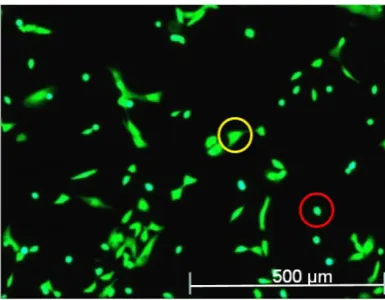
used in order to digitize images. Figure 3.6 shows the short-term viability assay result on a
Figure 3.6. Fluorescence microscopy image of SKOV-3 cells grown for 24 h on TCPS as control, after stain-ing with Calcein AM. 10X magnification.
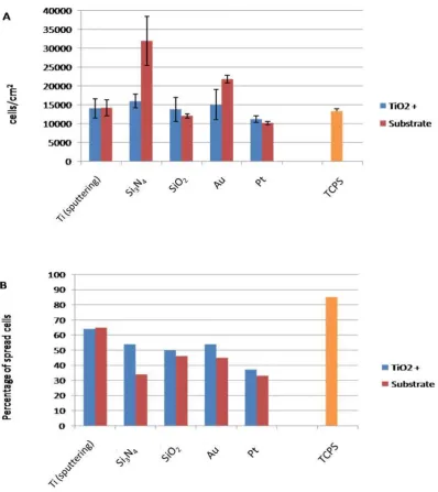
Results of Calcein AM tests obtained on the microfabricated and functionalized materials
are summarized in Figure 3.7. In general, these images reveal all a good bioaffinity of the
employed materials, with a more evident higher cell density on Si3N4. Moreover, a homo-geneous cell growth characterized every sample and no cellular debris were detected as
Since the Calcein AM assay is specific for the identification of viable cells, it represented a
useful tool for a precise cell density evaluation. A direct counting of labelled cells on
im-ages allowed to calculate the Viable Cell Density for each type of substrate:
Viable Cell Density = total amount of viable cells/cm2
In particular, an average