Please cite this article as: W. J. Lee, P. S. Goh, W. J. Lau, C. S. Ong, A. F. Ismail, Zwitterion Embedded Thin Film Composite Membrane for Oily Wastewater Treatment, International Journal of Engineering (IJE), IJE TRANSACTIONS B: Applications Vol. 31, No. 8, (August 2018) 1464-1472
International Journal of Engineering
J o u r n a l H o m e p a g e : w w w . i j e . i rZwitterion Embedded Thin Film Composite Membrane for Oily Wastewater
Treatment
W.J. Leea, P.S. Goh a*, W.J. Laua, C.S. Ongb, A.F. Ismaila
a Advanced Membrane Technology Research Centre (AMTEC), Universiti Teknologi Malaysia, 81310 Skudai, Johor, Malaysia b Department of Environment Technology and Management, College of Life Sciences, Kuwait University, Kuwait
P A P E R I N F O
Paper history:
Received 22 December 2017 Received in revised form 07 April 2018 Accepted 09 March 2018
Keywords:
Forward Osmosis
Thin Film Composite Membrane Oily Wastewater
Zwitterion
A B S T R A C T
Recent development in oil and gas industry increases the production and consumption of oil. The enormous amount of oily wastewater produced is urged to be treated, in order to prevent humanity and environment from being threatened. Membrane technology is an appealing alternative for oily wastewater treatment due to its design simplicity, energy efficiency and gentle environmental approach. In this study, a poly[3-(N-2-methacryloylxyethyl-N,N-dimethyl)-ammonatopropanesulfonate] (PMAPS) incorporated thin film composite (TFC) membrane with excellent anti-fouling properties was fabricated for oil removal from oily wastewater through forward osmosis process. PMAPS was blended with the polyethersulfone (PES) dope solution and casted into PES support layer. The TFC was fabricated via interfacial polymerization (IP) technique to form a thin film polyamide (PA) layer a top of a PES support layer. The PMAPS incorporated TFC membranes has been characterized for their morphology, surface hydrophilicity and charges. The incorporation of PMAPS was compatible with the PES polymer matrix hence lead to defect-free thin film formation. Prior to the hydrophilicity of PMAPS, the resultant 1% PMAPS-TFC membrane exhibited a high water flux of 15.12±0.3 L/m2.h and oil flux <0.1±0.08 g/m2.h, reverse salt flux of 3.93±0.4 L/m2.h under
Forward osmosis (FO) mode using emulsified oily solution as feed solution and 2M NaCl as draw solution using active layer-feed solution (AL-FS) orientation. A 99% of oil rejection was obtained. Also, PMAPS incorporated TFC membrane was able to outperform neat TFC membrane with lower fouling propensity for oily waste treatment.
doi: 10.5829/ije.2018.31.08b.39
NOMENCLATURE
Operating duration (min) V Volume of permeate (mL)
A Effective area of membrane (m2)
P Applied pressure difference (bar)
Y Salt permeability coefficient (Lm-2h-1bar-1) R
o Oil rejection (%)
Rs Salt rejection (%) Jo Oil flux (L m-2 h-1)
Cf Conductivity of feed (S) Jv Water flux (L m-2 h-1)
Cp Conductivity of permeate (S) Js Salt flux (L m-2 h-1)
Jo Flux determined at the beginning in the filtration Jo,FO Oil flux under FO mode (L m-2 h-1)
1. INTRODUCTION1
The recent development in oil and gas industries increased the consumption of oil. However, the technical and management developments which are not synchronized with the pace cause waste oil to be disposed directly into water without further treatment.
*Corresponding Author Email: peisean@petroleum.utm.my (P. S. Goh)
drinking water and groundwater and aquatic sources; threaten human’s health and lives; create atmospheric pollution; reduce crop production and destroy the natural landscape [2] Thus, the urge of treating oily wastewater is becoming increasingly more important.
There are several readily available technologies for oily separation. Flotation is considered a simple way of removing oil from wastewater. As wastewater is poured in the form of fine bubbles, the oil particles will adhere to the tiny air bubbles and will be suspended in the water, prior to the lower density of oil particles. Then the scum layer formed will be removed from water [3]. The advantages of flotation is high processing capacity, high separation efficiency and low sludge production. However, flotation also suffers from limitations such as potential manufacturing and repairing problems, as well as high energy consumption. Coagulation is another separation technology where emulsified and dissolved oil along with some difficult biodegradable polymers can be removed. Prior to its ability to destabilize and aggregate colloids, the popular is widely used. Besides, the advantage of being able to reach very high oil removal efficiency, up to 99% with the aids of aggregation zinc silicate (PISS) and anionic polyacrylamide (A-PAM) composite flocculant also causes its popularity [4]. However, in these approaches, repeated testing must be carried out to screen and choose the suitable chemical required to treat the complex wastewater composition. Apart from that, these processes suffer from high cost and can easily cause secondary pollution of water bodies. Biological treatment utilizes microbial metabolism to treat wastewater. As the water is dissolved, organic pollutants will be changed into harmless substances and stabilized [5]. Biological treatment is commonly used in activated sludge and biological filter methods. There are several advantages of biological treatment such as eco-friendly and high thermostability. However, the process is very time-consuming, which could take up from weeks to months [6]. Most of the methods above face high energy consumption or environmental barrier with stable emulsified oil prior to the size of oil droplets which are normally less than 20 μm because of the stabilizing effect from surfactants .
Membrane technology is an effective way to treat oily wastewater as it is effective to fully remove suspended solids and biological degradable organic components from wastewater. There are several types of membrane technologies commonly used to treat oily wastewater, such as ultrafiltration (UF), nanofiltration (NF) and reverse osmosis (RO). When the oil feed concentration is too high, UF is not able to scale down the oil concentration of oily wastewater to a disposable level. It requires a secondary treatment using NF and RO to further remove the residual oil [7-9]. All these processes require high pressure and high energy to work
on. To ensure continuous productivity, higher frequency of membrane cleaning as well as larger membrane area are also possibly required [10, 11]. Hence, a new technology namely forward osmosis (FO) which applies the similar principle as other membrane technologies has won itself an important seat in wastewater treatment. Instead of high hydraulic pressure of requirement to function well, FO utilizes the osmotic pressure gradient as the driving force to separate pure water from feed solution. Apart from that, FO is also deemed to have some other advantages compared to UF, NF and RO such as lower energy required, lower membrane fouling rate, easier fouling removal [12] and higher water recovery rate [13]. Consequently, FO has received in-depth studies throughout the recent years across various latent applications [14]. FO is good for oily removal as the process is not pressure driven thus membrane fouling would be lower. FO is also good in removing a wide range of impurities within the oily wastewater [15]. Although membrane fouling is relatively lower than other pressure-driven processes, its effect is still considered significant in FO thus need to be solved as to maintain the durability and prolong the life-span of the membrane [16].
significant improvements in salt rejection and water permeation flux. Additionally, the surface fouling in the TFC membrane is reported to be lower as well.
Based on the desired hydrophilic properties possessed by zwitterion, the objective of the current study was to investigate the effects of incorporation of zwitterion in the polymer substrate of TFC for oily wastewater treatment. Poly[3-(N-2-methacryloxyethyl- N, N-dimethyl)-ammonatopropanesulfonate (PMAPS) was the chosen zwitterion for the study as it exhibits oil detachment behaviour in both water and aqueous NaCl solution [23]. This is the first attempt of fabricating single-skinned zwitterionic TFC membranes for oily wastewater treatment. The effects of zwitterionic polymers on the oily wastewater treatment process were investigated based on the oil rejection rate and water flux.
2. EXPERIMENTAL
2. 1. Materials Polyethersulfone (PES) in pellet
form (Arkema), Polyvinylpyrrolidone40 (PVP40, Sigma Aldrich) and N-methyl-2-pyrrolidone (NMP, purity > 99.5%, RC1-Labscan) as addictive were used for
fabrication of membrane substrate.
m-Phenylenediamine (MPD) and trimesoyl chloride (TMC) from Sigma Aldrich were used to form PA a top PES substrate. To synthesize zwitterion properties polymer, 2-(dimethylamino) ethyl methacrylate
(DMAEMA, 95%), 2-bromoisobutyrate bromide,
diisobutylaluminium hydride (1.0 M in toluene), ethyl 2-bromoisobutyrate (EBiB, 98%), 1,3-propanesultone (99%), dipyridyl (Bpy, AR), 2-bromoisobutyryl bromide (98%), copper(I) bromide (CuBr, 99%) and 1-hexyl-3-methylimidazolium chloride (HMImCl) were purchased from Sigma Aldrich. Diethyl ether was purchased from RCl-Labscan. Sodium chloride (NaCl, Merck) was used as draw solution. sodium dodecyl sulfate (SDS, Sigma Aldrich) was used as emulsifying agent for mixing of crude oil and deionized (DI) water.
2. 2. Membrane Preparation The components
used to prepare polymer dope solution for fabrication of membrane substrate layer comprise of 18 wt.% PES, 1 wt.% PVP and 81 wt.% NMP. Different loadings of PMAPS, 1% and 5% of PMAPS were used in substrate formation as well. Steps and conditions applied during casting and post treatment of PES membrane are similar to casting procedures by Lau et al. [16]. To fabricate a TFC membrane, IP was performed, whereby PA layer was formed a top PES support layer using MPD and TMC monomers.
2. 3. Membrane Characterization FESEM (Supra 35VP, Carl Zeiss) was used for characterization of the
surface and cross-sectional morphologies of PMAPS-PES support layer and TFC. Morphological studies are significant as it can provide information about the structure of membranes which were used to describe membrane performance and determine possible defects formation. The thickness of TFC skin layer was also measured using FESEM. The membrane samples were prepared by freezing in liquid nitrogen, then fractured and placed onto the stud before being coated with gold using sputter-coating machine. To obtain the surface morphologies, scanning was done at a magnification of ×5k, operating at 2 kV, whereas the cross-sectional morphologies was determined at magnification of ×600 and/or ×20k which operates at 1 kV. To determine the roughness of PMAPS-PES substrate, Nanowizard 3 from JPK Instruments (Contact mode) was used. Samples were cut into 1cm × 1cm pieces and being sticked on a flat glass slide. Then it was sent for AFM scanning using contact mode. The scanning area was 10 μm × 10 μm. To detect the chemical compounds on the fillers and the membranes, FTIR (Frontier-GPOB, Perkin Elmer), was used to detect the characteristic bands of functional groups and specific bonds via infrared spectroscopy. Comparison of the infrared spectrum of modified membrane substrate with its neat counterpart eased the identification process by highlighting the odd infrared absorption bands. Analysis was done on the skin layers of the membrane substrate. Spectrum will be recorded from 600 cm-1 to 4000 cm-1. Water contact angle measurement was conducted using contact angle system OCA (708381-T, LMS Scientific). By the system, it was able to observe the movement of water across the membrane. The contact angle measurement and movement of water across membrane were used to identify the hydrophilicity of the membrane surface. A small rectangular piece of sample of around 3 mm × 70 mm length and width was cut off from the TFC membrane. It was then fixed on the platform and one water droplet was dropped on the surface of TFC each instance by adjusting the height of platform. Contact angle between membrane surface and water was observed and recorded using computer by software SCA20. 10 instances were repeated by adjusting the platform from side to side. Average values were obtained for the high accuracy.
2. 4. Pure Water Permeability, Salt Permeability
and Salt Rejection Test A commercial stirred
obtain a more accurate result, the test was repeated in triplicate and average reading was taken. The pure water permeability coefficient, denoted as X (Lm-2h-1bar-1) was calculated using Equation (1)
X= 𝑉×6𝐷
𝐴∆𝑡∆𝑃×1𝑑𝑑𝑑 (1)
where V is the volume of permeate (mL), A is the effective area of membrane (0.00146 m2), t is the operating duration (min), P is the applied pressure difference (bar).
For salt flux and salt rejection test, the DI water was used to compress the membrane for 30 min before carrying out the experiment. After that, the process was similar but only the DI water was replaced by 2000 ppm of NaCl solution. It was allowed to run for another 15 min to achieve a stabilized flux. 2 mL of salt permeate was collected and the time taken was recorded. The process was repeated thrice to get an average reading. The salt rejection was determined based on differences between feed and permeate conductivity using a conductivity meter (HC3010, Trans Instruments). The salt permeability coefficient, Y (Lm-2h-1bar-1) and salt rejection, Rs (%) were calculated using Equations (2) and (3), respectively.
Y = (2)
Rs = (3)
where Cp and Cf represent the conductivity of the permeate and the feed (S), respectively.
2. 5. Oil Flux and Oil Rejection Tests The steps
are completely similar to the previous tests. DI water and salt solution used were replaced with 1000 ppm of crude oil (Red Eagle, Malaysia) in water. The crude oil was mixed with SDS in a ratio of 1:9 in order to obtain a homogenous oil emulsion which was similar to steps reported in literature [24]. To obtain the oil rejection, the oil feed and permeate concentrations were determined using UV-vis spectrometer (DR2800, Hach). The absorbance was being measured at 273 nm which showed the peak where most absorbance occurred. The oil flux and oil rejection were calculated according to Equations (4) and (5)
Jo = (4)
Ro = (5)
where Cp and Cf represents concentration of oil permeate and oil feed (abs), respectively.
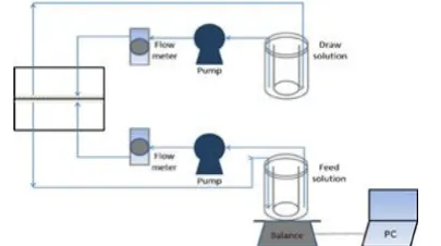
2. 6. Forward Osmosis Test The cross-flow FO cell where membrane was attached on has an effective membrane area of 20.02 cm2. The system was operated
at 1 bar throughout the process to circulate the FS and draw solution (DS) using two variable speed pumps. AL-FS orientation was being employed, with the temperature and velocity of FS and DS were fixed at ambient temperature and 32.72 cm/s, respectively. 1000 ppm of oily wastewater was used as the feed solution while 2.0 M of concentrated salt solution was used as the draw solution. A digital weight balance was placed at the bottom of draw solution tank to obtain a precise water flux. A fixed cross flow rate of 500 mL/min was used to circulate both FS and DS. Figure 1 further shows the complete setup for a FO system. Figure 2 shows crossflow profile of TFC membrane. The water flux was obtained by applying Equation (6):
Jv= (6)
where V is the volume change of the feed solution (mL), A is the effective area of membrane (0.002 m2)
t is the operating time interval (h).
Whereas, the reverse salt flux was calculated by applying Equation (7) based on change in salt concentration and volume of feed solution:
Js = (7)
where Cf (g/L) and V (mL) are the change in salt concentration in feed solution and volume of feed solution measured at the beginning and the end of time interval accordingly.
Figure 1. Schematic diagram of a bench-scale forward
osmosis setup for testing of the TFC membrane setup [25]
A conductivity meter was used to measure the conductivity of the feed solution and converted the respective values into concentration using a calibration graph. Also, the oil flux can be obtained using Equation (8)
Jo,FO = (8)
where Cd (g/L) and V (mL) are the change in oil concentration and volume of draw solution measured at the beginning and the end of time interval accordingly. The concentration of draw solution was obtained by converting the absorbance of the draw solution using UV-vis spectrometer (DR 2800, Hach).
3. RESULTS AND DISCUSSION
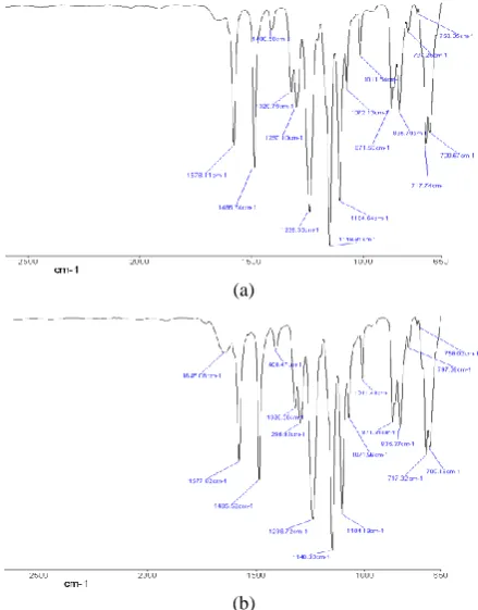
3. 1. Membrane Characterization The successful incorporation of PMAPS can be confirmed by observing the specific characteristic bands from Figure 3. According to Zhu et al. [26], the characteristic band of – O-C=C group which belongs to the PMAPS polymer is presented at around 1715 cm-1, as shown in Figures 3(b) and 3(c), while Figure 3(a) which represents neat substrate membrane does not have such characteristic band. Although the peak was not labelled, it however can be observed that as the PMAPS loading increases, the peak become more distinguish.
(a)
(b)
(c)
Figure 3. FTIR spectra of substrate membranes, (a) neat
substrate, (b) 1% PMAPS-PES substrate, (c) 5% PMAPS-PES substrate
The change in the surface water contact angle indicates the change of surface hydrophilicity. The 1% PMAPS-TFC membrane has a contact angle of 34.49±3.54 o while neat TFC membrane has a contact angle of 59.567±4.4 o. This indicates that the incorporation of PMAPS grants membrane surface with higher hydrophilicity. Meanwhile, the 5% PMAPS-TFC membrane has a contact angle of 42.32±12.29 o. The relatively large standards deviation is probably due to the uneven pore formation and pore size which causes water droplet to have different contact angles at different parts of membrane surface.
(a)
(b)
(c)
Figure 4. FESEM images of TFC membranes’ cross-sectional
morphology, (a) 1% PMAPS-TFC, (b) 5% PMAPS-TFC (c) neat TFC
(a)
(b)
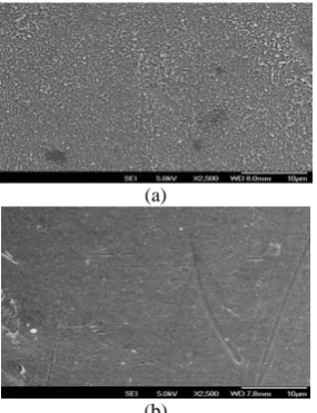
Figure 5. FESEM images of membranes’ surface, (a) TFC
surface with PA layer, (b) PES substrate surface
From the AFM images, the Ra parameter which indicates the surface roughness increases accordingly from neat membrane (Ra=38.22 nm), 1% PMAPS-TFC
membrane (Ra=65.97nm) to 5% PMAPS-TFC
membrane (Ra=99.61 nm). Hence, it is deduced that as the loading of PMAPS increases, the surface roughness of membrane increases as well.
(a)
(b)
(c)
Figure 6. AFM images of (a) neat TFC (b) 1% PMAPS-TFC
(c) 5% PMAPS-TFC
It also tallies to the previous deduction which states that excessive loading of PMAPS tends to cause uneven membrane pore distribution as the surface roughness is directly related to pore formation. The thickness of membranes however is not affected by the PMAPS loadings, but solely due to inconsistent membrane casting speed and strength. The thickness of the membranes are 4.39 µm, 6.98 µm and 2.92 µm in sequence of neat membrane, 1% PMAPS-TFC membrane and 5% PMAPS-TFC membrane.
3. 2. Oily Wastewater Treatment Performance
Testing Figures 7(a) and 7(b) show comparisons
(a)
(b)
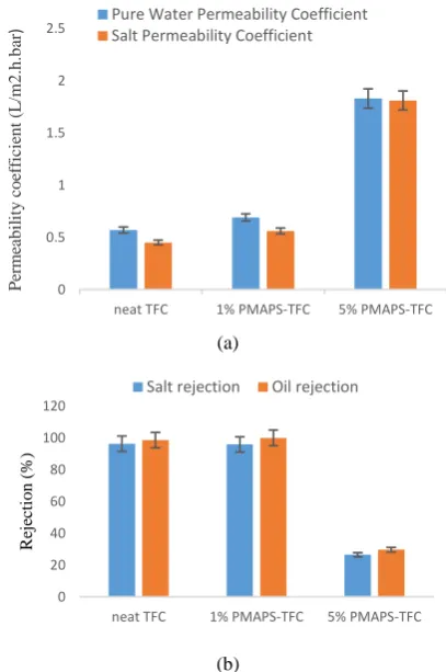
Figure 7. Transport properties of neat TFC and PMAPS-TFC
membranes, (a) pure water permeability coefficient and salt permeability coefficient and (b) salt rejection and oil rejection for DI water, 2000 ppm NaCl solution and 1,000 ppm emulsified oil solution tested under RO mode at 15 bar
Nonetheless, while comparing permeability coefficient with respect to rejection, it can be noticed that both neat TFC and 1% PMAPS-TFC membranes grant very high rejection rates which are 96.2% of salt rejection and 98.5% of oil rejection for neat TFC membrane, and 95.8% of salt rejection and 99.9% of oil rejection for 1% PMAPS-TFC membrane; meanwhile rejections for 5% PMAPS-TFC membrane is comparatively low, which are 26.5% and 29.6% for both salt and oil rejections. This indicates that PMAPS at high loading has negative effect on the thin film PA layer formation. The non-uniform pores distributed randomly across the membrane surface contributes to the poor performance of 5% PMAPS-TFC. From the results, it can be induced the substrate layer with uneven macroporous distribution upon the addition of 5% PMAPS has disrupted the polymerization of MPD and TMC, hence a defective PA selective layer was formed. Thus, to avoid the undesirable trade-off effect as observed in 5% PMAPS-TFC, the amount PMAPS zwitterion used must be in moderation during membrane formation. While comparing neat TFC membrane to 1% PMAPS-TFC
membrane, the higher permeability coefficients can be attributed to the enhanced hydrophilicity of PMAPS as evidenced from the contact angle measurement of the membranes’ surfaces.
Table 1 compares the flux performance between neat TFC membrane and PMAPS-TFC membrane. Using 1000 ppm of emulsified oil solution as feed solution while 2M NaCl as the draw solution under AL-FS mode, it can be observed that the 1% PMAPS-PES membrane grants higher water flux and reverse solute flux than neat TFC membrane. Moreover, while 1% PMAPS-PES membrane is capable in providing higher water flux (15.12 LMH) compared to neat membrane (12.54 LMH), it at the same time gives high quality water with purity > 99.9%.
TABLE 1. Flux performance of the neat TFC membrane and
PMAPS-TFC membrane Types of
Membranes
Water Flux,
Jv (LMH)
Reverse SoluteFlux,
Js (LMH)
Oil Flux, Jo (gMH)
Neat TFC 12.54 3.56 < 0.02
1%
PMAPS-PES 15.12 3.93 < 0.01
5%
PMAPS-PES 31.58 24.52 0.39
4. CONCLUSION
A PMAPS incorporated TFC membrane is effective in oil emulsion water treatment under FO mode. The successful PMAPS incorporation has been confirmed by obtaining the characteristic band of 1715 cm-1. 1% PMAPS-TFC has much lower water contact angle (34.49±3.54 o) than neat membrane (59.567±4.4 o) due to the great hydrophilicity of PMAPS. All the membranes have long-finger like structure and highly porous middle which eases the water transportation across the membrane. The higher the loading of PMAPS, the rougher the membrane surface. Apart from that, the zwitterionic properties of PMAPS helps to increase the membrane’s hydrophilicity and resulted in higher water flux of 15.12 LMH compared to neat membrane of 12.54 LMH using 2M NaCl as draw solution. At the same time, it is also able to provide very decent oil rejection up to 99.9% and oil flux of <0.01 gMH. Under RO mode, the pure water permeability coefficient and salt permeability coefficient of PMAPS-TFC membrane are also decent which are 0.69 and 0.56 LMH, respectively. However, excessive loading of PMAPS can cause non-uniform pores of different sizes distributed randomly throughout the membrane structure resulting in distorted membrane structure and properties thus poor performance. Characterizations from FESEM and AFM further prove the validity of this 0
0.5 1 1.5 2 2.5
neat TFC 1% PMAPS-TFC 5% PMAPS-TFC
P
er
me
ab
il
it
y
c
o
ef
fi
ci
en
t
(L
/m
2
.h
.b
ar
) Pure Water Permeability CoefficientSalt Permeability Coefficient
0 20 40 60 80 100 120
neat TFC 1% PMAPS-TFC 5% PMAPS-TFC
R
ej
ec
ti
o
n
(
%)
statement. The present study shows the feasibility of incorporating PMAPS into the TFC substrate via a facile blending method. Further studies on the antifouling properties will be reported in the near future.
5. ACKNOWLEDGEMENT
The authors would like to acknowledge the financial supports provided by Ministry of Higher Education (HiCOE Grant: 4J182) and Universiti Teknologi Malaysia (Research University Grant: 13H65).
6. REFERENCES
1. Huang, S., Ras, R.H. and Tian, X., "Antifouling membranes for oily wastewater treatment: Interplay between wetting and membrane fouling", Current Opinion in Colloid & Interface
Science, (2018).
2. Poulopoulos, S., Voutsas, E., Grigoropoulou, H. and Philippopoulos, C., "Stripping as a pretreatment process of industrial oily wastewater", Journal of hazardous materials, Vol. 117, No. 2-3, (2005), 135-139.
3. Moosai, R. and Dawe, R.A., "Gas attachment of oil droplets for gas flotation for oily wastewater cleanup", Separation and
purification technology, Vol. 33, No. 3, (2003), 303-314.
4. Zeng, Y., Yang, C., Zhang, J. and Pu, W., "Feasibility investigation of oily wastewater treatment by combination of zinc and pam in coagulation/flocculation", Journal of
hazardous materials, Vol. 147, No. 3, (2007), 991-996.
5. Kriipsalu, M., Marques, M., Nammari, D.R. and Hogland, W., "Bio-treatment of oily sludge: The contribution of amendment material to the content of target contaminants, and the biodegradation dynamics", Journal of hazardous materials, Vol. 148, No. 3, (2007), 616-622.
6. Ghasemian, P., Sharghi, E.A. and Davarpanah, L., "The influence of short values of hydraulic and sludge retention time on performance of a membrane bioreactor treating sunflower oil refinery wastewater", International Journal Of Engineering, Vol. 30, No. 10, (2017), 1417-1424.
7. Park, E. and Barnett, S.M., "Oil/water separation using nanofiltration membrane technology", Separation Science and
Technology, Vol. 36, No. 7, (2001), 1527-1542.
8. Kasemset, S., Lee, A., Miller, D.J., Freeman, B.D. and Sharma, M.M., "Effect of polydopamine deposition conditions on fouling resistance, physical properties, and permeation properties of reverse osmosis membranes in oil/water separation", Journal of
membrane science, Vol. 425, (2013), 208-216.
9. Bagheripour, E., Moghadassi, A. and Hosseini, S., "Preparation of polyvinylchloride nanofiltration membrane: Investigation the effect of thickness, prior evaporation time and addition polyethylenglchol as additive on membrane performance and properties", International Journal of
Engineering-Transactions C: Aspects, Vol. 29, No. 3, (2016), 280-287.
10. Hickenbottom, K.L., Hancock, N.T., Hutchings, N.R., Appleton, E.W., Beaudry, E.G., Xu, P. and Cath, T.Y., "Forward osmosis treatment of drilling mud and fracturing wastewater from oil and gas operations", Desalination, Vol. 312, (2013), 60-66. 11. Duong, P.H., Chung, T.-S., Wei, S. and Irish, L., "Highly
permeable double-skinned forward osmosis membranes for anti-fouling in the emulsified oil–water separation process",
Environmental science & technology, Vol. 48, No. 8, (2014),
4537-4545.
12. Mi, B. and Elimelech, M., "Organic fouling of forward osmosis membranes: Fouling reversibility and cleaning without chemical reagents", Journal of membrane science, Vol. 348, No. 1-2, (2010), 337-345.
13. Martinetti, C.R., Childress, A.E. and Cath, T.Y., "High recovery of concentrated ro brines using forward osmosis and membrane distillation", Journal of membrane science, Vol. 331, No. 1-2, (2009), 31-39.
14. Song, X., Wang, L., Tang, C.Y., Wang, Z. and Gao, C., "Fabrication of carbon nanotubes incorporated double-skinned thin film nanocomposite membranes for enhanced separation performance and antifouling capability in forward osmosis process", Desalination, Vol. 369, (2015), 1-9.
15. Zhang, S., Wang, P., Fu, X. and Chung, T.-S., "Sustainable water recovery from oily wastewater via forward osmosis-membrane distillation (fo-md)", water research, Vol. 52, (2014), 112-121.
16. Lau, W., Gray, S., Matsuura, T., Emadzadeh, D., Chen, J.P. and Ismail, A., "A review on polyamide thin film nanocomposite (tfn) membranes: History, applications, challenges and approaches", water research, Vol. 80, No., (2015), 306-324. 17. Liang, H.-Q., Hung, W.-S., Yu, H.-H., Hu, C.-C., Lee, K.-R.,
Lai, J.-Y. and Xu, Z.-K., "Forward osmosis membranes with unprecedented water flux", Journal of membrane science, Vol. 529, No., (2017), 47-54.
18. Tiraferri, A., Yip, N.Y., Phillip, W.A., Schiffman, J.D. and Elimelech, M., "Relating performance of thin-film composite forward osmosis membranes to support layer formation and structure", Journal of membrane science, Vol. 367, No. 1-2, (2011), 340-352.
19. Bagheripour, E., Moghadassi, A. and Hosseini, S., "Incorporated poly acrylic acid-co-fe3o4 nanoparticles mixed matrix polyethersulfone based nanofiltration membrane in desalination process", International Journal Of Engineering, Vol. 30, No. 6, (2017), 821-829.
20. Gholami, F., Zinadini, S., Zinatizadeh, A., Noori, E. and Rafiee, E., "Preparation and characterization of an antifouling polyethersulfone nanofiltration membrane blended with graphene oxide/ag nanoparticles", International Journal of
Engineering-Transactions A: Basics, Vol. 30, No. 10, (2017),
1425-1433.
21. Chan, W.-F., Marand, E. and Martin, S.M., "Novel zwitterion functionalized carbon nanotube nanocomposite membranes for improved ro performance and surface anti-biofouling resistance", Journal of membrane science, Vol. 509, (2016), 125-137.
22. Chan, W.-F., Chen, H.-y., Surapathi, A., Taylor, M.G., Shao, X., Marand, E. and Johnson, J.K., "Zwitterion functionalized carbon nanotube/polyamide nanocomposite membranes for water desalination", Acs Nano, Vol. 7, No. 6, (2013), 5308-5319. 23. Kobayashi, M., Terayama, Y., Kikuchi, M. and Takahara, A.,
"Chain dimensions and surface characterization of superhydrophilic polymer brushes with zwitterion side groups",
Soft Matter, Vol. 9, No. 21, (2013), 5138-5148.
24. Han, G., de Wit, J.S. and Chung, T.-S., "Water reclamation from emulsified oily wastewater via effective forward osmosis hollow fiber membranes under the pro mode", water research, Vol. 81, No., (2015), 54-63.
25. Chun, Y., Kim, S.-J., Millar, G.J., Mulcahy, D., Kim, I.S. and Zou, L., "Forward osmosis as a pre-treatment for treating coal seam gas associated water: Flux and fouling behaviour",
Desalination, Vol. 403, No., (2017), 144-152.
26. Zhu, Y., Zhang, F., Wang, D., Pei, X.F., Zhang, W. and Jin, J., "A novel zwitterionic polyelectrolyte grafted pvdf membrane for thoroughly separating oil from water with ultrahigh efficiency",
Journal of Materials Chemistry A, Vol. 1, No. 18, (2013),
Zwitterion Embedded Thin Film Composite Membrane for Oily Wastewater
Treatment
W.J. Leea, P.S. Goha, W.J. Laua, C.S. Ongb, A.F. Ismaila
a Advanced Membrane Technology Research Centre (AMTEC), Universiti Teknologi Malaysia, 81310 Skudai, Johor, Malaysia b Department of Environment Technology and Management, College of Life Sciences, Kuwait University, Kuwait
P A P E R I N F O
Paper history:
Received 22 December 2017 Received in revised form 07 April 2018 Accepted 09 March 2018
Keywords:
Forward Osmosis
Thin Film Composite Membrane Oily Wastewater
Zwitterion
هديكچ
شیازفا ار تفن فرصم و دیلوت زاگ و تفن تعنص رد ریخا هعسوت تسا هداد
. طیحم و تیرشب دیدهت زا یریگولج یارب
دوش یم دیلوت هک ینغور یاه بلاضاف زا یدایز رادقم تسیز یم هیفصت تایلمع دنمزاین
دنشاب . نیزگیاج یاشغ یروآ نف
یارب باذج فصت
هی طیحم یاه درکیور و یژرنا یرو هرهب ،نآ یحارط یگداس تلع هب ینغور بلاضاف یتسیز
دروم نآ
تسا هتفرگ رارق هجوت
.
یاشغ هعلاطم نیا رد
PMFP
اب
بلاضاف زا تفن فذح یارب یگتفرگ دض یلاع یاه یگژیو
.تسا هدش هتخاس سوکعم زمسا دنیارف قیرط زا یتفن
PMAPS
لولحماب
نیئتورپ
PES
طولخم
و هدش ناونع هیلا یتظافح PES لمع یم دنک . TFC
شور زا هدافتسا اب نویسازیرمیلپ یحطس هتخاس تسا هدش هیلا ات دیمآ یلپ کی یلااب رد ار
ظفاحم هیلا
PES
.دهد لیکشت یارب
هنومن
PMAPS
یاهاشغ لماش
TFC
،یژولوفروم راب و حطس یتیسیلیفردیه
تسا هدش لیلحت و هیزجتاه
.
تسویپ
PMAPS
یرمیلپ سیرتام اب
PES
کزان ملیف لیکشت هب رجنم و هدوب راگزاس نودب
دوش یم صقن
.
لیفوردیه زا لبق
ندوب PMAPS ، هنومن ۱ ٪
PMAPS-TFC
،ءاشغ نایرج بیترت هب تفن و بآ یلااب لااب
اب ربارب ۱۵ . ۱۲ ± ۰ . ۳ h . 2 m / L و ۰ . ۱ ± ۰ . ۰۸ .h 2 m / g ناشن دنهدیم سوکعم راش کمن لداعم ۰ . ۴۳ ± ۳ . ۹۳ h 2
L / m
تلاح رد
FO
و یکاروخ لولحم ناونع هب نویسلوما نغور لولحم زا هدافتسا اب
۲
MNaCl
لح هار ناونع هب هدش حرطم
لاعف لولحم هیلا هیذغت تهج
(AL-FS)
.
99 ٪
یزاس ادج تسد هب تفن تسا هدامآ ،نینچمه . PMAPS یاشغ لماش TFC یرتهب درکلمع هب تبسن یاشغ TFC هک
یارب یرتمک لیامت یزاس ادج
یتفن یاه بلاضاف ار
یم اراد دشاب .