Printed in The Islamic Republic of Iran, 2006 © Shiraz University
A NEW DIFFERENTIAL PROTECTION ALGORITHM BASED ON RISING
RATE VARIATION OF SECOND HARMONIC CURRENT
*M. E. HAMEDANI GOLSHAN
**AND H. SAMET
Dept. of Electrical and Computer Engineering, Isfahan University of Technology, Isfahan, I. R. of Iran Email: [email protected]
Abstract– In this paper, a new algorithm based on processing differential current harmonics is proposed for digital differential protection of power transformers. This algorithm has been developed by considering different behaviors of second harmonic components of the differential currents under fault and inrush current conditions. In the new method, a criterion function is defined in terms of the time variation of the second harmonic rising rate during instants after the occurring disturbance. By evaluating the signs of the criterion function for the three phases, the internal faults can be accurately recognized from inrush current conditions in less than a half-cycle after the occurrence of a disturbance; this is one advantage of the method. Another advantage of the proposed method is that the fault detection algorithm does not depend on the selection of thresholds. A suitable performance of this method will be demonstrated by the simulation of different faults and switching conditions on a power transformer. For this purpose, a small part of the Iran power system involving a power transformer and the transmission lines on both sides of the transformer has been considered. To include effective factors on differential current components, the elements of this power system have been precisely modeled in PSCAD/EMTDC.
Keywords– Transformer differential protection, differential current components, inrush current, fault current, criterion function
1. INTRODUCTION
The power transformer is an important component of power systems for which various protective schemes have been developed. The differential protective system establishes the main protection against short circuits occurring on transformer windings. This protective system should operate rapidly when internal faults occur. However, it should not operate under non-fault conditions such as a flowing inrush current. In digital differential relays, differential currents or other required signals are sampled and processed according to protective algorithms.
Most of the fault detection algorithms in the digital differential protection of power transformers are based on processing the harmonic content of the differential currents. These methods utilize the fact that the ratio of the second harmonic to the fundamental component of differential currents under inrush current conditions is greater in comparison to that under fault conditions.
To enhance the reliability of differential protection, several methods have utilized voltage signals as well as current signals [1]. In [2], a differential power method has been proposed to recognize the fault situation from inrush current conditions. The proposed method in [3] is based on the modal transform of voltage and current waveforms. Disadvantages of these methods include the need to use voltage transformers and increased protective algorithm calculation costs.
In another class of methods, fault conditions are recognized by the distortion characteristic of the differential current waveform. One of these methods operates via measurement of intervals between two
∗
Received by the editors January 4, 2004; final revised form April 4, 2006. ∗∗
successive peaks of a differential current waveform [4]. The operation criterion in another method is the duration in which the differential current waveform remains near zero [5]. Delayed fault detection is the disadvantage of this group of algorithms.
Various methods based on processing differential current harmonics have been proposed to detect internal faults occurring in power transformers. In some of these methods, differential current harmonics are used as inputs to a learned neural network [6]. The output of the neural network indicates the transformer situation. In [7], a set of developed fuzzy laws based on differential current harmonics has been proposed as a differential protection algorithm. The problem associated with these methods is the need to design neural networks or fuzzy laws, which require a huge number of learning patterns produced by simulations of various cases. Generally, practical and commercial differential relays detect internal fault events through evaluating one or more inequalities. Both sides of the inequalities are special combinations of differential current harmonics. These simple algorithms are divided into two main groups: harmonic restraint methods (HR) and harmonic blocking methods (HB). Various algorithms in these groups have been introduced in [8]. The performance of these algorithms is considerably affected by the selection of coefficients used in fault detection relationships. Usually, these coefficients are experimentally selected. In addition, the security of HR algorithms is greater than that of the HB methods under inrush current conditions, while HB methods detect fault conditions with less delay.
Recently, we have proposed a new algorithm based on processing differential current harmonics for the digital differential protection of power transformers [9]. This algorithm was developed by considering different behaviors of the second harmonic component of differential currents under fault and inrush current conditions. The method can recognize internal faults from inrush current conditions by evaluating the sign of four quantities, three criterion functions defined in terms of the time variation of the second harmonic of three-phase differential currents and their average. In this paper, in order to reduce the computation effort, a new and modified algorithm is proposed that does not need to evaluate the sign of the average of three criterion functions. For this purpose, a criterion function is defined in terms of the time variation of the second harmonic rising rate during instants after the occurring disturbance. By evaluating the sign of criterion function for three phases, the internal faults can be more accurately recognized from the inrush current conditions in less than the half-cycle after the occurrence of the disturbance. Similar to the algorithm in [9], another advantage of the proposed method is that the fault detection algorithm does not depend on the selection of thresholds. The suitable performance of this method will be demonstrated by the simulation of different faults and switching conditions on a power transformer. For this purpose, a small part of the Iran power system involving a power transformer and the transmission lines on both sides of the transformer has been considered. To include effective factors on differential current components, the elements of this power system have been modeled in PSCAD/EMTDC.
Following this introduction, the power system under study is described in section 2. In the next section, the characteristics of inrush and fault currents are compared in view of the second harmonic. Then, we illustrate the bases of the new method and the manner in which these characteristics are used to recognize faults from the inrush current. The capability of the proposed method is demonstrated via results obtained from various simulations in section 4.
2. THE POWER SYSTEM UNDER STUDY
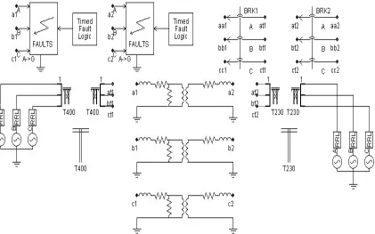
contribute. For this purpose, a small part of the Iran power system, including a power transformer 500 MVA, 400/230 kV, current transformers related to its differential protection, and transmission lines existing on both sides of the power transformer has been modeled in PSCAD/EMTDC. Modeling has been made so that the power system under study can be subjected to different conditions such as switching and different internal and external faults. The diagram of this power system is shown in Fig. 1.
Fig. 1. Diagram of the simulated power system
Windings of each side of the three-phase power transformer have a star connection with earthed neutrals. We will examine the capability of the proposed algorithm in the presence of a delta-connected tertiary winding in section 4. The magnetizing branch in the transformer equivalent circuit is modeled as a nonlinear voltage-current curve. To model current transformers, we have utilized the facilities of PSCAD/EMTDC developed for power transformer modeling.
The model used for 230kV and 400kV transmission lines is the more detailed model in which the parameters of lines are considered in a distributed form, so effects of the distributed parameters of transmission lines on inrush and short circuit current waveforms are included. The rest of the power system is modeled by the Thevenin equivalent circuits connected to transmission lines. In this manner, a suitable power system, along with a more detailed modeling, has been provided to extract disturbance current waveforms under different conditions of fault and inrush current. Thus we can accurately test the performance of the proposed algorithm under different conditions.
3. NEW METHOD TO DISCRIMINATE BETWEEN INRUSH AND FAULT CURRENTS
a) Different behavior of normalized second harmonic component of inrush and fault currents
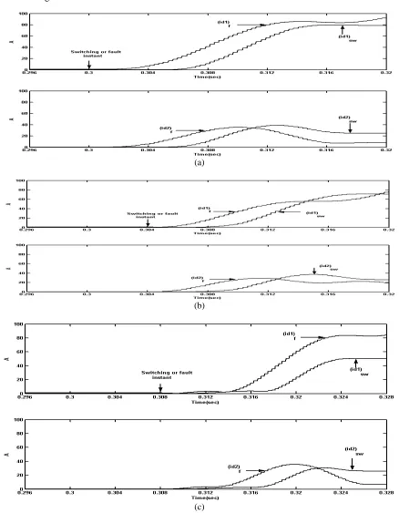
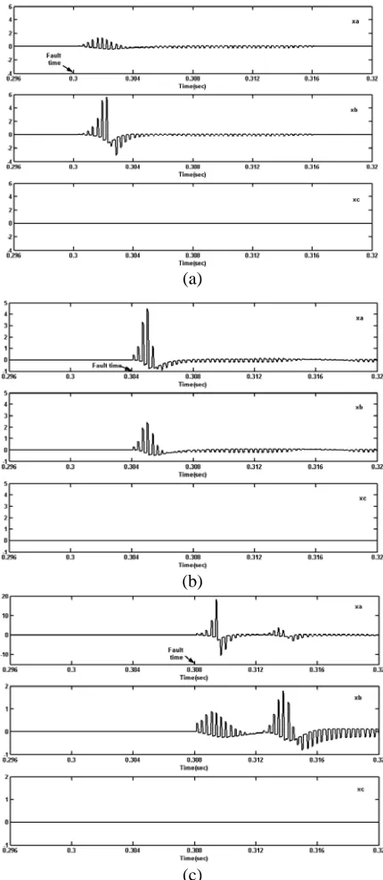
The fundamental component and second harmonic of differential currents have different behaviors under fault and inrush current conditions. Figure 2.a shows fundamental and second harmonic components of the differential current of phase A under the inrush current condition ((id1)sw,(id2)sw), and in the case of single phase to earth short circuit on the winding of phase A of the transformer ((id1)f,(id2)f ). Both switching and short circuit have occurred at timet =0.3s. For the purpose of comparison, fundamental and second harmonic components of differential currents related to switching conditions have been magnified thirty times. Different behavioral characteristics such as increase or decrease rates, the time variation of increase or decrease rates and the time of reaching the peak of similar components under different disturbance conditions can be easily observed. If switching or a fault occurs at other instants, then the characteristics of differential current components change somewhat, but the relative behavior of these components remains almost constant under fault and inrush conditions. This fact is seen in Figs. 2.b and 2.c, which show plots similar to Fig. 2.a for the occurrence of disturbances at times t =0.304sand
s 308 0
t = . respectively. It should be noticed that 400 samples per power frequency period are produced by simulations performed in PSCAD/EMTDC, but we use only 64 samples per cycle for extracting fundamental and second harmonic components of differential currents by Fourier transform. In other words, values of fundamental and second harmonic components calculated, for example, at time t =t1are assumed constant until the next six samples produced by simulations in PSCAD/EMTDC.
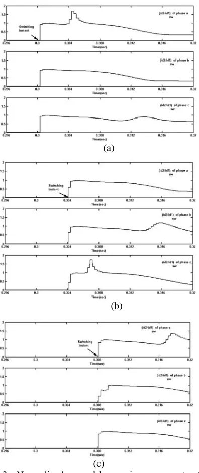
The magnitude of differential current components can be very different under the inrush current and fault condition as shown in Fig. 2. However, if the second harmonic component of the differential current are divided by the fundamental component of this current, the magnitude of the normalized second harmonic component will fall to a narrow band under all conditions. Thus, they can be easily compared. This point is observed in Figs. 3 and 4. The important observation from Figs. 3 and 4 is that the normalized second harmonic components ((id2 /id1)sw) of the three phases rise with the biggest rates just after switching, then the rising rates gradually reduce during the next instants. On the other hand, under internal fault conditions, the rising rate of the normalized second harmonic components ((id2/id1)f ) gradually increase during instants after the occurrence of the fault. These special characteristics do not depend on the instants of switching or the occurrence of faults. These behavioral characteristics of the normalized second harmonic component have been used in developing the new algorithm. Below, we will show how these characteristics can be used in the proposed fault detection algorithm.
b) Bases of the proposed fault detection algorithm
Based on the above explanations, it seems that the time variation of the rising rate of normalized second harmonic components during instants after an occurring disturbance is a suitable index for discriminating between internal faults and inrush current conditions. Thus, we define function
X
(
n
)
in then
th sample as follows:) 2 ( 2 ) 1 ( 2 ) ( 2 2 )
( = − − + Dn− n
D n
D I I
I n
X (1)
plots of
X
(
n
)
for inrush current and internal fault conditions given in Figs. 5 and 6 are respectively presented in Figs. 7 and 8.(a)
(b)
(c)
Fig. 2. Fundamental and second harmonic components of phase A differential current under inrush current
. conditions and internal fault. Switching and fault occur at time (a) t=.3s (b) t=.304s (c) t=.308s
(a) (a)
(b) (b)
(c) (c) Fig. 3. Normalized second harmonic components of
differential current of three phases under inrush current conditions. Switching occurs at time (a) t=.3s (b) t=.304s (c) t=.308s
Fig. 4. Normalized second harmonic components of differential current of three phases under single phase to ground (A-G) fault conditions. Fault occurs at time (a) t=.3s (b) t=.304s (c) t=.308s
c) Criterion function for discriminating between internal fault and inrush current conditions
As a consequence of the above observations, we define the criterion function for the fault detection algorithm as:
∑
= ⎟⎟⎠
⎞ ⎜⎜
⎝ ⎛
+ − = n
a
i i a
i X n
f
) 1 (
) ( )
( (2)
where a is the number of differential current samples corresponding to time, about 0.8 ms after switching or the internal fault instant, and
n
=
a
,
a
+
1
,
a
+
2
,
a
+
3
,...
In each samplen,
f
(
n
)
is a function of the area under curveX
(
n
)
. The first sample in the formula ofeliminates the initial errors introduced in values of fundamental and second harmonics of differential currents due to the harmonics extracting method. Here, it should be mentioned that to extract the frequency components of differential currents, we have utilized the signal processing capability of PSCAD/EMTDC. Specifically, on line FFT with 64 samples per period of power, frequency has been utilized. As time increases from the instant of the disturbance, the behavior of
X
(
n
)
function can be reversed. Term(
i
−
a
+
1
)
in the denominator of the criterion function is a weighting factor that increases with time. This term has been included to eliminate the effect due to the reversing behavior ofX
(
n
)
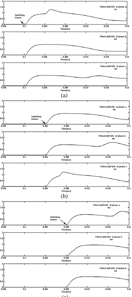
as time increases.Fig. 5. Filtered and normalized second harmonic components of differential current of three phases under inrush current conditions. Switching occurs at time (a) t=.3s (b) t=.304s (c) t=.308s
Fig. 6. Filtered and normalized second harmonic components of differential current of three phases under single phase to ground (A-G)fault conditions. Fault occurs at time (a) t=.3s (b) t=.304s (c) t=.308s
(a)
(b)
(c) (a)
(b)
Fig. 7. Functions Xn for differential current of three
phases under inrush current conditions. Switching occurs at time (a) t=.3s (b) t=.304s (c) t=.308s
Fig. 8. Functions Xn for differential current of three
phases under internal fault (A-G) condition. Fault occurs at time (a) t=.3s (b) t=.304s (c) t=.308s
d) Algorithm of the proposed method
The algorithm of the proposed method for internal fault detection is as follows:
I. Occurrence of disturbance (switching or fault) is detected. Various methods can be used to detect the disturbance. We do not consider how to detect disturbances in this paper.
II. If the bias characteristic indicates that the disturbance is an external fault, then the evaluation process will be finished; consequently, relay does not operate. Otherwise, the next step will be executed.
III. The functions
X
andf
of three phases of differential currents(
f
a,
f
b,
f
c)
are calculated fortimes after the occurrence of the disturbance.
(a)
(b)
(c)
(a)
(b)
IV. If the disturbance is a fault condition, then at least the sign of one of the functions
f
a,
f
b,
f
c will be positive. Under an inrush current condition, all of the functionsf
a,
f
b,
f
care negative.The simulation results have demonstrated that a fault condition can be recognized from an inrush current condition in less than a half-cycle after the occurrence of disturbance by determining the signs of three functions
f
a,
f
b,
f
c. Therefore, if at least the sign of one of these functions becomes positive in a half-cycle after the occurrence of a disturbance, then the disturbance is an internal fault and relay should send a trip command. Otherwise, relay should not operate.4. SIMULATION RESULTS
To demonstrate the security, dependability and suitable speed of the proposed method, different kinds of faults and switching cases have been simulated on the power system as introduced in section 2. In this section, results of these simulations are presented.
a) Simulation of different kinds of faults and switching conditions for the base case
As the first case, different kinds of fault conditions including single phase to ground, phase to phase and three phase faults have been applied to 230 kV and 400 kV windings of a power transformer at different phase-angles of the supplying voltage. We have considered ten different instants of a power frequency cycle for the occurrence of each kind of fault. Table 1 summarizes the results of applying the proposed algorithm to the differential current of three phases. The numbers included in the table show magnified values of criterion functions at some times about a half-cycle after the occurrence of a fault. It is observed that the sign of at least one of the criterion functions becomes positive in less than a half-cycle after the occurrence of a fault under all internal fault conditions.
For instance, criterion functions related to differential currents of the three phases for a single phase to ground fault (including phase A) occurred at the zero-crossing instant of phase A voltage waveform and 4ms and 8ms after this instant, are shown in Fig. 9. It is observed that the sign of functions
f
a,
f
bbecomepositive in less than a half-cycle after the occurrence of a fault. Thus, the digital differential relay operates and sends a trip signal.
Table 1 summarizes the results of applying the proposed algorithm to different switching conditions too. It is assumed that the power transformer has been energized at different phase-angles of the supplying voltage. The phase-angles correspond to instants 0, 1, 2, … 9 ms after zero-crossing time of supplying the voltage waveform.
Figure 10 shows the criterion functions for three different switching conditions. Switching has been made at the zero-crossing instant of the voltage waveform of one of the three phases and 4ms and 8ms after this instant. It is clearly observed that all of the three criterion functions take negative signs in less than a half-cycle after switching time and remain negative for the next time.
b) Effect of changing power system and transformer parameters on performance of the proposed algorithm
The simulation results have demonstrated that the proposed algorithm performance does not fail by changing transformer parameters such as the core shape, windings connections, adding tertiary winding and magnetization characteristics. For example, Table 2 indicates the results of applying the proposed algorithm to faults and switching conditions for the case in which the excitation current required for a given applied voltage is twice of that in the base case.
Table 1. Magnified values of criterion functions for different kinds of faults and switching conditions in the base case (t: disturbance occurrence instant)
Table 2. Studying effect of changing magnetizing characteristic of the power transformer on the proposed algorithm (Ifnew=2Ifold)
Table 3. Results of applying the proposed algorithm to a case that the short circuit capacities of the 400kV and 230kV power systems are 3000MVA and 1500MVA Fault
t fa fb fc t fa fb fc
a-g 4 5 0 a-g 15 4 0
a-b 4 30 7 a-b 16 3 3
a-b-g 4 30 11 a-b-g 16 3 3
.3
a-b-c 10 30 19
.305
a-b-c 3 3 5
a-g 6 11 0 a-g 41 4 0
a-b 6 28 9 a-b 28 4 3
a-b-g 7 28 11 a-b-g 40 4 2
.301
a-b-c 2 29 15 .306
a-b-c -13 4 13
a-g 12 17 0 a-g 93 6 0
a-b 11 19 11 a-b 18 5 3
a-b-g 12 19 12 a-b-g 82 5 19
.302
a-b-c 12 19 14
.307
a-b-c -90 5 33
a-g 8 8 0 a-g 17 3 0
a-b 6 2 5 a-b 2 21 3
a-b-g 6 2 5 a-b-g 16 8 14
.303
a-b-c 7 2 5
.308
a-b-c 31 6 40
a-g 4 2 0 a-g 2 1 0
a-b 3 -3 2 a-b 2 1 0
a-b-g 1 -3 2 a-b-g 2 21 11
.304
a-b-c -4 -3 1
.309
a-b-c 2 22 24
Switching
t fa fb fc t fa fb fc
.3 -17 -17 -17 .305 -17 -17 -17
.301 -14 -15 -15 .306 -15 -16 -16
.302 -13 -14 -14 .307 -14 -13 -14
.303 -14 -14 -14 .308 -14 -10 -14
.304 -15 -15 -15 .309 -15 -17 -15
Fault
t fa fb fc
a-g 3 4 0
a-b 3 18 5
a-b-g 4 18 7
.3
a-b-c 7 18 12
a-g 6 2 0
a-b 3 -1 1
a-b-g 2 -1 1
.304
a-b-c -4 -1 1
a-g 7 1 0
a-b 3 9 2
a-b-g 9 10 8
.308
a-b-c -22 8 37
Switching
t fa fb fc
.3 -17 -17 -17
.302 -13 -14 -14
.304 -15 -15 -15
.306 -15 -15 -16
.308 -14 -10 -14
Fault
t fa fb fc a-g 4 4 0 a-b 5 22 6
a-b-g 5 21 9
.3
a-b-c 7 21 15
a-g 8 3 0 a-b 7 -1 2
a-b-g 4 -1 2
.304
a-b-c -8 -1 2
a-g 11 3 0
a-b 2 6 10
a-b-g 11 6 10
.308
a-b-c -7 5 43
Switching
(a) (a)
(b) (b)
(c) (c) Fig . 9. Criterion functions calculated for internal single
phase to ground fault. The fault occurs at time a) t=.3s, b) t=.304s, c) t=.308s
Fig. 10. Criterion functions for a typical inrush current condition of transformer. The switching occurs
at, a) t=.3s, b) t=.304s, c) t=.308s
5. CONCLUSION
REFERENCES
1. Inagaki, K. & Higaki, M. (1998). Digital protection method for power transformers based on an equivalent circuit composed of inverse inductance, IEEE T-PWRD, 3(4), 1501.
2. Yabe, K. (1997). Power differential method for discrimination between fault and magnetizing inrush current in transformers, IEEE T-PWRD, 12(3), 1109.
3. Sidhu, T. S. & Sachdev, M. S. (1992). On line identification of magnetizing inrush and internal faults in three phase transformers, IEEE T-PWRD, 7(4), 1885.
4. Rockefeller, G. D. (1969). Fault protection with a digital computer, IEEE T-PAS, 98, 438.
5. Giuliante, A. & Clough, G. (1991). Advances in the design of differential protection for power transformers, proc. 1991 Georgia Tech. Protective Relaying Conf., 1, 1-12.
6. Bastard, P., Meunier, M. & Regal, H. (1995). Neural network-based algorithm for power transformer differential relays, IEE Proceeding C, 142(4), 386.
7. Wiszniewski, A. & Kasztenny, B. (1995). A multi-criteria differential transformer relay based on fuzzy logic, IEEE T-PWRD, 10(4), 1786.
8. Guzman, A., Zocholl, S., Benmouyal, G. & Altuve, H. J. (2001). A current-based solution for transformer differential protection- part 1: problem statement, IEEE T-PWRD, 16(4), 485.