Developing Reliable yet Flexible Software through
If-Then Model Transformation Rules
Abbas Rasoolzadegan
i*and Ahmad Abdollahzadeh Barforoush
iiDeveloping reliable yet flexible software is a hard problem. Although modeling methods enjoy a lot of
advantages, the exclusive use of just one of them, in many cases, may not guarantee the development of
reliable and flexible software. Formal modeling methods ensure reliability because they use a rigorous
approach to software development. However, lack of knowledge and high cost practically force developers
to use semi-formal methods instead. Semi-formal (visual) modeling methods, which are widely used in
practical large-scale software development, are not good enough for reliable software development. This
paper proposes a new approach to the development of reliable yet flexible software by transforming formal
and semi-formal models into each other. In this way, the advantages of both methods are incorporated in to
the software development process. The structured rules, proposed in this paper, transform formal and visual
models into each other through the iterative and evolutionary process. The feasibility as well as the
effectiveness of the proposed approach is demonstrated using the multi-lift system as a test case.
Keywords
Model transformation, flexibility, design patterns, UML, reliability, Object-Z
i *
Corresponding Author, A. Rasoolzadegan is with the department of Information Technology and Computer Engineering, Amirkabir University of Technology, Tehran, Iran (e-mail: rasoolzadegan, @aut.ac.ir).
ii A. Abdollahzadeh Barforoush is with the department of Information Technology and Computer Engineering, Amirkabir University of Technology, Tehran, Iran (e-mail: [email protected]).
1. INTRODUCTION
Studies show that the major causes of software failure are vague and incomplete elicitation, specification, analysis, validation, and verification of customer requirements [9], [11-12]. All activities during Requirements Engineering (RE) are expected to address the aforementioned causes in the software development life cycle. Moreover, in practice, software development suffers from premature emphasis on code which is not at the right level of abstraction to encourage thinking about problems and the design of their solutions. Contemporary literature recognizes the vital role of reliability and flexibility in software development [8-9]. Modeling plays a crucial role to develop reliable and flexible software through presenting the appropriate level of abstraction during the different phases of software development, ranging from RE to detailed design. Models are used to specify, analyze, validate, and verify the artifacts developed throughout the development cycle [9-10]. This is the idea behind Model-Driven Software Engineering (MDSE), an approach that advocates models, rather than code, as the primary artifacts of software development. The focus of MDSE is on modeling. In MDSE models are systematically transformed into code. MDSE is supported by two broad groups of modeling methods called formal modeling methods (FMMs) and semi-formal modeling methods (SFMMs).
FMMs are broadly defined as notations with accurate and unambiguous semantics and are supported by various tools. FMMs mathematically prove the consistency and completeness of activities during software development. Such proofs help detect all errors before they turn into defects. In addition, the correctness insured by proof is more comprehensive and reliable than the correctness guaranteed by test. These advantages facilitate the development of correct and reliable software.
Despite the above-mentioned advantages of FMMs, lack of knowledge and high cost restrict their use to the development of critical and high integrity software [9], [14]. The flexibility of software depends on the use of software engineering (SE) principles that are largely heuristic and are more akin to developers’ innovation, experience, and tacit (implicit) knowledge than their formal (explicit) knowledge [13]. In order to develop high-quality software, in general, and flexible software, in particular, the direct involvement of stakeholders, particularly designers, is needed. The review and analysis of formal models proves to be a difficult task for the stakeholders who are not familiar with the concepts of formal methods. This reduces the flexibility of software being developed.
main strengths of SFMMs: 1) intuitive and widely known notations, which strengthen and promote the interactions among project stakeholders such as analyzers and designers, 2) methodological support emphasizing problem decomposition, and 3) making it possible to exploit the heuristic and narrative principles of SE during the software development process, which increases the flexibility. However, their syntax and semantics are not enough for an effective verification of a software application. This weakness, in turn, causes some side effects such as lack of automated analysis and lower reliability.
A detailed report of the advantages and limitations of FMMs and SFMMs has been presented in [7]. A significant case study, called the multi-lift system, has also been taken as a test bed [4-5]. This system is a commonly used test bed which demonstrates the expressive power of different modeling languages in specifying concurrent, reactive systems. The significance of this case study lies in the complexity caused by inherent concurrent interactions in the system. The advantages and shortcomings of semi-formal and semi-formal modeling methods have been investigated by surveying the literature [7] and specifying the multi-lift system case study in an empirical manner [4]. This investigation shows that a combination of both methods would be required for the correct and complete specification, validation, and verification of requirements as well as the flexible and reliable design of solutions. Achieving high-quality software through such a combination seems sound. Although some valuable attempts have been made to integrate these methods to exploit the advantages of both formal and semi-formal modeling methods, there is a long way ahead to reach the promised goals [9-10], [59-60].
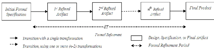
The problem to be addressed in this paper is to develop reliable yet flexible software [6]. Figure 1 illustrates the formal software development process, using FMMs. This process starts with an initial formal specification which abstractly states the stakeholders’ requirements. Then, the details of design are added to the initial specification through a gradual process (T), using formal refinement [9]. This process contains several intermediate artifacts refined by transformations andcontinues until producing the final product.
If the initial formal specification accurately represents the informal functional requirements of the stakeholders, using FMMs as the sole approach to software development guarantees high reliability as a non-functional requirement. However, FMMs do not necessarily help meet other non-functional requirements such as flexibility with a desired quality. The heuristic and narrative techniques of SE, such as design patterns, directly affect the flexibility of software. Effective use of these techniques entails developers’ innovation, experience, and tacit knowledge. Therefore, designers
should have an effective and direct involvement in the interval T indicated in Figure 1. In many cases, this involvement may not be possible due to designers’ lack of familiarity with formal languages. This problem reduces the flexibility of software during the formal software development process. All issues relating to FMMs have been discussed in [7].
A detailed report of the problem domain, the key terms that are required to communicate the scope, the contributions of this work, and the motivation are fully elaborated in [6-7]. This paper presents a new approach to solving the problem of the development of reliable yet flexible software. This approach enables the construction of formal models from semi-formal ones and vice versa in an iterative and evolutionary manner. The former is called formalization, and the latter is called visualization. We evaluate the proposed approach via the multi-lift system.
The rest of this paper is organized as follows: Section 2 describes the proposed approach. This approach utilizes a new bidirectional rule-based mechanism for model transformation between Object-Z and UML as well as some heuristic techniques of SE to ensure the desired reliability and flexibility. The proposed transformation mechanism is elaborated in this section. The process of developing a reliable and flexible multi-lift system through the proposed approach is presented in section 3. Section 4 investigates compares the related studies. Finally, section 5 draws conclusions and discusses future works.
2. THEPROPOSEDAPPROACH
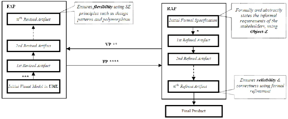
This work presents a new approach to the development of reliable yet flexible software through model transformation between Object-Z and UML. Figure 2 illustrates a schematic view of the proposed approach which consists of the following phases:
1. Reliability Assurance Phase (RAP) which supports formal specification and refinement in Object-Z. 2. Visualization Phase (VP) which transforms Object-Z
models into UML ones.
3. Flexibility Assurance Phase (FAP) which revises UML models from the viewpoints of design patterns and polymorphism.
Figure 1: Formal Software Development Process
In RAP, according to stakeholders’ requirements, the initial formal specification is produced as the first artifact, using Object-Z. The RAP contains several intermediate artifacts referred to as refined artifacts. The
th
i 1)
( artifact contains more details of design than the ith artifact. The details of design are gradually added to the artifacts through a process which involves several formal refinement steps. Formal refinement ensures the correctness of the produced artifacts. The newly refined formal artifact is passed to VP, as soon as the artifact needs to be reviewed by some SE heuristic techniques.
In VP, the input formal model is visualized in UML by a set of rules. More specifically, the input Object-Z specification is transformed into a UML class diagram. Class diagrams facilitate the process of reviewing the structure and the behavior of the software from the viewpoints of design patterns and polymorphism. The produced visual model is then passed to FAP.
In FAP, the initial visual model is gradually revised, using some heuristic techniques, i.e. some behavioral design patterns and polymorphism. This review improves the flexibility of the visual models [13]. Model refactoring is an appropriate way of preserving the behavior between the successive versions of the visualized models [60]. The last revised visual model is subsequently passed to FP.
In FP, the input class diagram is transformed into Object-Z specification using a set of rules. The produced formal model is passed to RAP, where the required details of design are gradually added to the input formal model, using formal refinement. This iterative and evolutionary process continues until a final product with a desired quality is achieved.
As illustrated in Figure 2, the proposed approach contains four transformation processes, namely formal refinement, visualization, model revision, and formalization. A model transformation in MDSE transforms an input model which conforms to a given meta-model into an output model that similarly conforms to a given meta-model. Based on the definition of model transformation, there are four kinds of transformation: 1) endogenous: the source and target meta-models are identical, 2) exogenous: the source and target
meta-models are different, 3) horizontal: the level of abstraction does not change, and 4) vertical: the level of abstraction changes. Formal refinement is an endogenous vertical transformation. Visualization and formalization are exogenous horizontal transformations. Model revision is an endogenous horizontal transformation.
Several rules in the phases FP and VP transform Object-Z specification into UML class diagram and vice versa. These rules cover all shared features of UML class diagrams and Object-Z specifications. These features are primary attributes, derived attributes, constants, operations, visibility, user-defined types, multiplicities, and initialization which constitute class, inheritance, generic inheritance, unidirectional association, bidirectionalassociation, aggregation, composition, and dependency which are different kinds of relationships, and associationclass and polymorphism. Since UML and Object-Z share basic object-oriented concepts, creating a systematic transformation between the two languages seems reasonable. Table 1 presents a detailed description of the proposed rules.
During FAP, design patterns are used to increase the flexibility and reusability of the structure and behavior of the software being developed. Behavioral design patterns, rather than structural and creational ones [13], are used in this phase. Among all behavioral design patterns, the focus is on Mediator, Observer, and Strategy.
The Mediator pattern defines an object named mediator. A mediator encapsulates how a set of objects, referred to as colleagues, interact. The Mediator pattern has the following benefits [13]:
Behavior is localized within a mediator rather than distributed among its several colleagues. Thus, behavior can be simply changed through subclassing a mediator without changing its colleagues.
A mediator decreases the coupling between its colleagues. Therefore, the mediator and its colleagues can be varied and reused independently.
Figure 2: A schematic view of the proposed approach
TABLE 1
BIDIRECTIONAL TRANSFORMATION RULES BETWEEN OBJECT-Z SPECIFICATION AND UML CLASS DIAGRAM
UML Object-Z
Class
Comments:
In Object-Z, a class contains state schema and operation schemas used to define state variables (primary and derived attributes) and operations, respectively.
In Object-Z, a class contains an INIT schema used to initialize state variables.
A constant, marked with {frozen} in UML, is represented in Object-Z as an axiomatic definition where its predicate expresses constraints on the constant introduced in its declaration.
Derived attributes, marked with / in UML, are distinguished from primary variables within Object-Z state schema through the Δ separator.
In UML and Object-Z, user-defined types such as T can be used. In Object-Z, the input and output variables of an operation are marked
with (?) and (!), respectively.
Initial State Schema User-defined Type
Operation Schemas State Invariant
(Predicate) Operation
s
Attributes
State Schema State Variables
(Declaration) Constant
Derived Attribute
Primary Attribute
Visibility List
Constant Definition Declaratio
n Predicate
Transformation Rules from UML into Object-Z:
If there is a UML class, then there is an Object-Z class with the same name.
If there is a feature (attribute or operation) marked with public (+) in a UML class, then the feature is added to the visibility list of the corresponding Object-Z class.
If there is a feature marked with private (-) or unadorned in a UML class, then the feature is not added to the visibility list of the corresponding Object-Z class.
If there is a primary attribute in a UML class, then a variable is declared with the same name within the state schema of the corresponding Object-Z class, above the separator (if any).
If there is a derived attribute in a UML class, then a variable is declared with the same name within the state schema of the corresponding Object-Z class, below the separator.
If there is a constant in a UML class, then a constant is declared with the same name within a separate constant definition schema of the
corresponding Object-Z class.
If there is an attribute such asattribute2 with the multiplicity greater than one in a UML class, then a variableis declared as a finite sequence of the same UML type, along with a cardinality predicate in the corresponding Object-Z class.
If there is an initial value such as t1 assigned to an attribute such as
attribute3 in a UML class, then the statement attribute3=t1 is added to the INIT schema of the corresponding Object-Z class.
If there is an operation in a UML class, then an operation is declared as an individual Object-Z operation schema with the same name, parameters, and return values within the corresponding Object-Z class.
If there is auser-defined type such as T declared as a finite set of values ({t1,t2}) in a UML class,then the statement T::t1t2 is defined as a free type within the corresponding Object-Z specification.
Transformation Rules from Object-Z into UML:
If there is an Object-Z class, then there is a UML class with the same name.
If there is a feature (attribute or operation) within the visibility list of a class in Object-Z, then the feature is marked with public (+) within the corresponding UML class.
If there is a feature, that is not in the visibility list of an Object-Z class then the feature is marked with private (-) within the corresponding UML class.
If there is a variable within the state schema of an Object-Z class, above the separator (if any), then a primary attribute is defined with the same name within the corresponding UML class.
If there is a variable within the state schema of an Object-Z class, below the separator, then a derived attribute with the same name is defined within the corresponding UML class.
If there is a constant declared within a constant definition schema of an Object-Z class, then a constant is defined with the same name within the corresponding UML class.
If there is an attribute as a finite sequence of a basic or user-defined type within Object-Z specification, then an attributeis defined with the same name and cardinality as an array of the same type within the corresponding UML class.
If there is a statement such as attribute3=t1 within the INIT schema of a class such as ClassA in Object-Z, then the initial value t1 is assigned to the attribute3 of ClassA in UML.
If there is an operation schema within Object-Z specification, then an operation is added to the corresponding UML class with the same name, parameters, and return values.
If there is afree type such as T with some distinct constants (t1t2) within Object-Z specification, then auser-defined type is declared as T{t1,t2} in UML.
Inheritance
Comments:
In Object-Z, overridden operations such as Operation1 are marked with
redef.
In UML, a subclass implicitly inherits all structural and behavioral features from its superclass.
In Object-Z, a subclass doesn't inherit the visibility list from its superclass. Thisenables a new interface to be defined.
Bidirectional Rules between UML and Object-Z:
If there is an inheritance relation between a subclass such as SubClass and a superclass such as SuperClass in a UML class diagram, then the name of the superclass ) SuperClass ( is stated immediately after the visibility list of the subclass )SubClass( inthecorresponding Object-Z specification and vice versa.
If there is an overridden operation such as Operation1 in a subclasssuch asSubClasswithin a UML class diagram, then the statement [redef Operation1] is stated immediately after the visibility list of the subclass )SubClass( inthecorresponding Object-Z specification and vice versa.
Generic Inheritance
Comment:
Generic inheritance is a mechanism for developing general-purpose structures.
Bidirectional Rule between UML and Object-Z:
If there is a generic inheritance within a UML class diagram between a superclass such as SuperClass with a generic type (
T
) and a subclass such asSubClass with a different type (
T
) then the statement SuperClass [T
] is stated immediately after the visibility list of the subclass )SubClass( in thecorresponding Object-Z specification and vice versa.Association
Unidirectional Association:
Bidirectional Association:
Comments:
In UML, an association relationship is represented as a line with an optional arrowhead which indicates the association direction in unidirectional relationships.
A UML association relationship may also include a notation at each end which indicates the multiplicity of the instances of the class attached to that end.
In a UML class diagram, an association relationship between two classes allows the objects of each of the two classes to have access to the objects of the other class depending on the association direction.Access may be: "sending a message", "invoking a method", or "calling a member function".
Bidirectional Rules between UML and Object-Z:
If there is a unidirectional association between two classes such as ClassA (at the arrowhead) and ClassB (at the tail of the arrow)in a UML class diagram, then in the state schema of ClassB, a variable is declared to identify an object of ClassA in the corresponding Object-Z specification and vice versa.
If there is a bidirectional association between two classes such as ClassA, with the multiplicity MA and the role as, and ClassB, with the multiplicity MB
and the role bsin a UML class diagram, then the state schemas of two corresponding Object-Z classes consists of 1) an attribute declared as a power set ( ) of the other class, 2) a constraint ensured actual links between instances of the two classes, and 3) a multiplicity constraint and vice versa.
Aggregation
Comments:
In a UML class diagram, an aggregation relationship is a kind of association which models "whole/parts" relationships.
In a UML class diagram, aggregation is represented as a hollow diamond on the side of the whole with a line that connects the whole to its parts. In an aggregation relationship, objects can exist independently.
The Object-Z notation for modeling an aggregation relationship is .
Bidirectional Rule between UML and Object-Z:
If there is an aggregation relationship between two UML classes such as ClassA (as the whole) referred to as a and ClassB (as the part)referred to as
bs, then the statements and is added to the state schema of the whole class (ClassA), respectively, as a declaration and a predicate in the corresponding Object-Z specification and vice versa.
Composition
Comments:
In a UML class diagram, a compositionrelationshipis a kind of an aggregation relationship, represented as a black diamond. In a composition relationship, the existence of each of its parts depends on the existence of its whole.
The Object-Z notation for modeling a composition relationship is©.
Bidirectional Rule between UML and Object-Z:
If there is a composition relationship between two UML classes such as ClassA (as the whole) referred to as a and ClassB (as the part)referred to as
bs, then the statements and are added to the state schema of the whole class (ClassA), respectively, as a declaration and a predicate in the corresponding Object-Z specification and vice versa.
Polymorphism
Comments:
Polymorphism isone of the basic principles of object-orientation which allows a variable to be declared whose value can be an object from any one of a given set of concrete classes that inherit from some abstract class.
Bidirectional Rule between UML and Object-Z:
If the relation of a UML class such as ClassA (referred to as a) with a hierarchy of classes such as AbstractClassB (referred to as b) and its childrenis based on polymorphism, then the statements and are added to the state schema of ClassA, respectively, as a declaration and a predicate within the corresponding Object-Z specification and vice versa.
Association Class
Comments:
In UML, an association class is attached to the corresponding association by a dashed line.
An association class contains information regarding the corresponding association relationship.
In UML and Object-Z, an association class is represented as a normal class.
An association class is often used for a many-to-one or many-to-many (*-*) association where the association itself has some attributes.
Bidirectional Rule between UML and Object-Z:
If there is an association class such as AssociationClassC attached to a primary associationwhich connects two UML classes such as ClassA (referred to as a) and ClassB(referred to as b),then
1)the declaration and the predicate are added to the state schema of ClassA, 2) the declaration and the predicate are added to the state schema of ClassB, and
3) the declarationsa: ClassA and b: ClassB and the predicates self a.band selfb.a are added to the state schema of AssociationClassC
within the corresponding Object-Z specification and vice versa.
Dependency
Comments:
In UML, dependencyis used to show that a class Client depends on another class (Supplier) for doing an operation Operation1. The class Client, placed at the tail of the arrow, depends on the class Supplier, placed at the arrowhead.
Transformation Rule from UML into Object-Z:
If a UML class (Client) includes an operation (such as Operation1)that depends on another class (Supplier),then in the corresponding Object-Z specification within Operation1 of Client, a variable is declared to identify an object of the class Supplier.
Transformation Rule from Object-Z into UML:
If there is a variable of Supplier type within Operation1 of Client in Object-Z, then a dependency relation is defined between Supplier and
Client in the corresponding class diagram such that Client is at the tail of the arrow.
The Observer pattern defines a one-to-many dependency between one object named subject and its dependent objects (observers). All observers are notified and updated automatically once the state of the subject changes. The benefits of the Observer pattern are as follows [13]:
It minimizes the coupling between a subject and its observers. A subject has the list of its observers. These observers conform to the interface of an abstract class named Observer. The subject knows only Observer, not all concrete classes of Observer.
It provides broadcast communication. A subject automatically broadcasts notifications to all its observers. The subject does not know how many dependent objects exist. It is only responsible for broadcasting notifications. Therefore, observers can be added or removed at any time in a flexible way. The Strategy pattern configures a class named context with one of several behaviors. The Strategy pattern has the following benefits [13]:
It provides a family of algorithms and behaviors as hierarchies of strategy classes for contexts to increase reusability.
It provides an alternative for subclassing. It encapsulates various algorithms in distinct strategy classes. This makes the algorithms have the ability to change or extend independently of the contexts easily. It eliminates conditional statements that are used for the selection of the desired behavior by encapsulating behavior in discrete strategy classes.
The proposed rule-based mechanism makes the use of formal refinement and SE heuristic techniques easy for developers to develop reliable yet flexible software.
3. CASESTUDY:MULTI-LIFTSYSTEM
We have been evaluated the proposed approach, using a non-trivial case study named multi-lift system. This section presents the results of this empirical evaluation [10]. The multi-lift system is controlled by a parallel, distributed, embedded, and real-time software. The software continuously processes the received information about passengers’ requests and lifts to move the lifts correct amount in the right direction. The multi-lift system, as a concurrent, reactive system, is a commonly test bed used for demonstrating the expressive power of modeling languages.
The multi-lift system that has been defined in this study consists of multiple lifts used in a building with multi-floors numbered from 1 to MaxFloor. Each floor has two direction buttons (except the top floor and the lobby). Passengers may press each of these buttons to go up or down. The top floor has only one down button. The lobby has only one up button. There is a panel of buttons named lift buttons inside each elevator each of which indicates a target floor. The door of an elevator is opened to allow passengers to enter or leave the car once the elevator stops in a floor. Each floor has an arrival sensor. Once an elevator reaches a floor, this sensor detects the elevator and stops the car. Each button can be pressed at any time. When a direction button is pressed in a floor, the button is turned on. Once an elevator with the same direction stops at the desired floor and opens the door, the button is turned off. Any pressed lift button is turned off when the lift visits the corresponding floor. This multi-lift system has all basic functions such as moving up and down, open and close doors, and pick up passengers. The central
controller of the system is responsible for controlling the lifts through their local controllers. Passengers interact with the lift system by pressing direction buttons (hall calls) or lift buttons (car calls).
Initially, all lifts stay on the standby floor. If a passenger enters a lift and presses the button that corresponds to the k-th floor, information about the request is sent to the central controller. Then the local controller of the lift moves the lift up to the k-th floor according to its dispatching strategy that has already been determined by the central controller. The dispatching strategy is determined for each lift according to some criteria such as manager policies and traffic mode [5]. When the lift arrives at the destination, the local controller opens the door for a certain period M seconds of time, then, closes it again, and the lift becomes idle or moves to the standby floor according to its strategy. Moreover, when a passenger on the m-th floor calls a lift by pressing the up or down button, the most suitable lift is moved to the m-th floor by the central controller and the door is opened on arrival. The passenger may press a lift button to reach his destination. If there is no passenger interaction on the control panel within M seconds, the lift will close the door and become idle on that floor.
The most suitable lift is selected by the central controller to respond to each of the external requests according to some criteria such as the current position and motion direction of the lifts. The central controller is evaluated according to various criteria such as average response time of passengers, percentage of passengers waiting more than 60 seconds, and power consumption. The central controller attempts to minimize the evaluation criteria; it is, however, difficult to satisfy all criteria at the same time. Therefore, the central controller is designed to meet each criterion at certain levels.
It is difficult to determine the most suitable elevator for the following reasons. First, the central controller is extremely complex; if a central controller manages n elevators and assigns p hall calls to the elevators, the controller considers p
n cases. Second, the controller must consider hall calls generated in the near future. Third, it must consider many uncertain factors, such as the number of passengers at the floors where hall calls and car calls are generated. Fourth, it must be possible for a system manager to change the control strategy. Some managers need to operate the system to minimize passenger waiting time while others want to reduce the power consumption. These factors increase the necessity of designing a flexible controller having the potential to change the control strategy dynamically.
approach in comparison with the case that only one of the aforementioned modeling methods (either formal or semi-formal) is used.
To meet the first criteria, initially, the Object-Z specification (
Z Object
M ) and UML class diagram (MUML) of the multi-lift system has been produced. By applying the proposed transformation rules to
Z Object
M and MUML,
'
UML M
and '
Z Object
M are respectively produced. Then MObjectZ and
UML
M are respectively compared with MObject' Z andMUML' .
The results of this comparison show that the correspondence ratio of these models is close to 1. The produced models have been presented, in detail, in [5].
The rest of this section evaluates the proposed approach from the viewpoint of the second criteria. Developing a reliable yet flexible multi-lift system using the proposed approach consists of the following steps: 1. The multi-lift system is initially specified using
Object-Z according to the given informal requirements. The initial formal specification is then refined formally to produce successive formal artifacts (in phase RAP). 2. At the time of reviewing the produced artifacts from the
viewpoints of some SE heuristic techniques, the last formal artifact is visualized in UML, using the proposed transformation rules (in phase VP).
3. Some SE techniques, i.e. some behavioral design patterns and polymorphism are used to revise the visualized model until achieving the desired flexibility (in phase FAP).
4. The last visual model is formalized, using the proposed transformation rules (in phase FP).
5. The formalized model is refined formally further until developing the final product (in phase RAP).
The simplified version of the models produced during these five steps is presented shortly. The fully-described version of the produced models has been comprehensively presented in [5]. The simplified version of the final artifact produced as the output of the first step is presented in Appendix A.
Appendix B illustrates the initial class diagram of the multi-lift system which corresponds to the above formal specification. Applying the proposed transformation rules to the above formal specification in the phase VP (the second step) results in the development of the initial class diagram. In order to show the amount of simplification made in the models presented in this section, as an instance, the full version of the initial class diagram is shown in Appendix C.
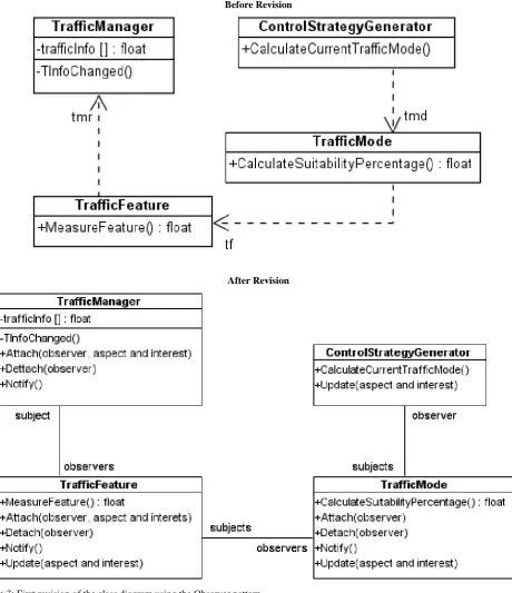
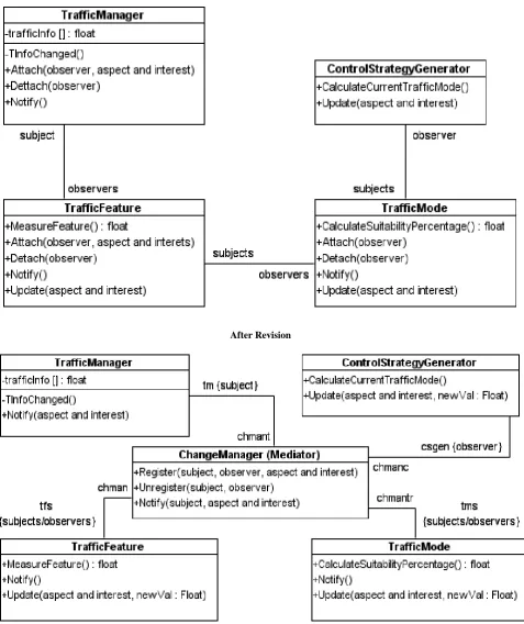
In the third step, by applying some SE techniques, i.e. the Observer, Strategy, and Mediator patterns and polymorphism to the initial class diagram of the multi-lift system, we discover which part is appropriate for revision by which technique. Figures 3 to 6 depict these parts before and after the revision.
As illustrated in the left column of Figure 3 (before
the revision), there are three dependencies between the objects of this part:
1. Whenever the traffic information (trafficinfo) managed by TrafficManager changes, the value of traffic features (objects of TrafficFeature) should be updated, using the method MeasureFeature.
2. Whenever the value of a traffic feature is updated, the suitability percentage of traffic modes (objects of TrafficMode) should be updated by the method CalculateSuitabilityPercentage.
3. Once the suitability percentage of a traffic mode is updated, the method CalculateCurrentTrafficMode of the class ControlStrategyGenerator determines the current traffic mode.
According to the application of the Observer pattern, this part is a suitable candidate for revision, using the Observer pattern. The right column of Figure 3 illustrates the revised version. In the Observer pattern, subjects implicitly know their observers. Any number of objects can observe a subject. Observers can be attached to subjects or be detached from them through the interface of subjects. Each subject sends a notification to its observers through calling their Update method whenever a change occurs to make the state of its observers consistent with its own. Moreover, an observer may ask the subject for information to reconcile its state with the state of the subject.
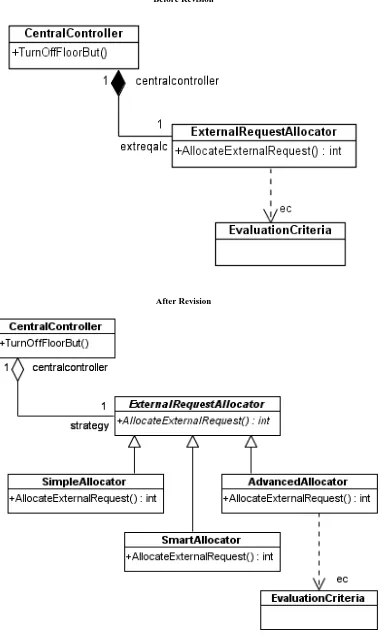
Figure 4 illustrates that the central controller (the class CentralController) contains an external request allocator (the class ExternalRequestAllocator). The role of such an allocator is to select the most suitable lift to respond to the current external request according to some parameters such as current values of the evaluation criteria (the objects of the class EvaluationCreteria). There are different strategies to respond to external requests according to various parameters such as managers’ policies (the association class ManagerPolicy) and the current traffic mode. These strategies need to change at run time according to values of the above-mentioned parameters. In order to meet the required flexibility for changing these strategies at run time, this part of the class diagram has been revised based on the Strategy pattern.
request of corresponding subject. The right column of Figure 5 illustrates the newly revised version of this part after applying the Mediator pattern.
Figure 6 shows the use of polymorphism in decreasing the coupling among objects which gives us the ultimate flexibility in extensibility. In polymorphism, more specific behaviors and structures are derived from less specific ones. Polymorphism allows us to define a common
interface of operations for objects of various types. This makes it possible to ask different objects to perform the same actions. In this revision, overriding has been used to realize the concept of polymorphism (the method press). Method overriding is where a subclass (such as LiftButton and AirButton) overrides the implementation of one or more of its parent's methods (the method press of the class Button).
Before Revision
After Revision
Before Revision
After Revision
Before Revision
After Revision
Figure 5: Third revision of the class diagram using the Mediator pattern
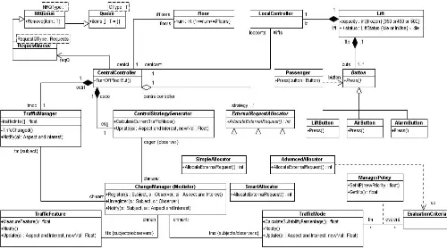
Figure 7 shows the final class diagram of the multi-lift system in a simplified form after applying the given behavioral design patterns and polymorphism to the initial one. The full version of the final class diagram is depicted in Appendix D. It is worth mentioning that all middle revisions of the multi-lift system's class diagram are fully
described in [5].
Before Revision After Revision
Figure 6: Fourth revision of the class diagram using Polymorphism
In the fifth step, the new formal specification has been refined further. The last refined formal specification of the multi-lift system has been presented in Appendix 4 in [5]. Thus, a flexible yet reliable multi-lift system has been specified using the proposed approach.
4. RELATED STUDIES
This work mainly focuses on the roles of modeling and model transformation in developing reliable yet flexible software. There have been several attempts in the area of model transformation with different purposes such as increasing the usability of formal models and increasing the accuracy of the semi-formal ones.
The work of Tilley [15] attempts to increase the usability of Z via line diagrams which represent Formal Concept Analysis (FCA). In response to the continued demand for tool support [10], [20-21], [62], as an alternative to increasing the usability of formal methods, this work develop a prototype tool for visualizing Z specifications based on FCA.
There have also been a number of approaches used to introduce graphical representations of Z specifications via UML [10]. The work of Sun, Dong, Liu, and Wang [62] provides an XML representation for the Z family of languages called ZML. ZML can be transformed into UML. A representative example is the work of Carrington and Kim [16]. Many approaches focus on the structural aspects of the specification. Kim and Carrington argue that, beyond the static structure of the specification, the dynamic nature and complex constraints must also be visualized for a full understanding of a specification. To do so, they propose two other graphical representations in addition to UML, one for the complex constraints and another for the operation schemas.
The use of formal methods has evolved over time. Initially, they were used with the aims of accuracy and well-defined semantics. When the tool support of formal methods was improved, approaches started to focus more and more on the use of formal methods for analysis and consistency-checking of semi-formal models. The studies by Evans and Clark [17] and Miao, Liu, and Li [18] combine Z and UML. However, these approaches focus on providing a formal basis for various aspects of UML in Z rather than visualizing Z specifications via UML. “Alloy” is a Z-related lightweight formal method with both textual and graphical components. Alloy offers a straightforward mapping from UML into a formal notation [19]. Lightweight formal methods provide “less than perfectly formal” or partial approaches for specification, validation, and testing [19]. Typically they make a trade-off between completeness and language functionality for efficiency. None of the approaches has achieved a full UML formalization. Instead, they focus on a restricted subset of the language. Most approaches do not even try to formalize all features of a diagram. They only focus on those features that are necessary for achieving their
purposes.
Studies in the area of method integration accompanied the evolution of SFMMs and FMMs. Initially, they focused on structured methods, then object-oriented ones and most recently on UML. There are several approaches to integrate structured methods (Yourdon, SSADM, etc.) with formal modeling languages such as VDM [22-23], Z [24-25], B [26], CCS [27], and algebraic-languages [28]. A more detailed study is given in [29]. The integrated approaches of structured methods try to do too much at once. They propose both the formalization of diagrammatic concepts and integration with structured methods. This affects the quality of formalization which is, in many cases, superficial. Integrated approaches of Object Oriented (OO) methods try to formalize the underlying concepts of object-orientation. There are some approaches to integrate OO methods with Z [30-35], Object-Z, B [36-42], [51], and CSP [43-46]. At this point, according to the goal of this work in transforming Object-Z specifications and UML class diagrams into each other, the already successful attempts to visualize the Object-Z specifications or to formalize models in Object-Z are discussed in more detail:
Metamorphosis is a method that integrates Object-Z with common features of OO methods [47]. It includes some translation rules for static and dynamic models. The method of Achatz and Schulte combines Fusion
with Object-Z [48].
Dupuy formalizes OO class models and state diagrams in Object-Z [49].
Chen and Miao visualize abstract Object-Z specification in UML diagrams [61].
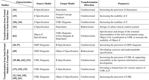
Kim and Carrington formalized UML class [3] and state diagrams [16], [50] in Object-Z; the mapping is also formally defined. However, this work does not formalize all features of class and state diagrams. Table 2 presents the related works that have been cited widely and are more relevant to the proposed approach. This table divides these studies into two categories: 1) the studies that transform formal models in B, Z, and Object-Z into semi-formal ones in FCA and UML, and 2) the studies that transform semi-formal models in OMT and UML into formal ones in B, Z, and Object-Z. In Table 2, the related studies have been identified by their source model, target model, transformation direction (unidirectional or bidirectional), and purpose(s). Unidirectional transformations are able to do transformation just in one direction. This means that a source model can be transformed into a target model though it cannot be transformed into a source model. Bidirectional transformations are executed in both directions.
use of the SE heuristic principles during the design process. There are also some attempts to integrate formal methods with design patterns [52-59]. All of these studies attempt to formalize some patterns of [13], but none of
them suggests the appropriate time and place for using the formalized behavioral patterns within the formal specification because of the heuristic nature of these patterns.
TABLE 2
IMPORTANT RELATED STUDIES IN THE AREA OF MODEL TRANSFORMATION
5. CONCLUSION AND FUTURE WORK
The widespread use of SFMMs helps use the heuristic techniques to develop highly flexible software. Despite all advantages of SFMMs, due to lack of well-defined semantics, SFMMs are not good enough for reliable software development. High-reliable software can be developed, using FMMs, which specify and verify software based on mathematical logic. Precise semantics allow FMMs to design the accurate models of software. However, their use has not been widely adopted due to lack of expertise and high cost.
The combination of both FMMs and SFMMs is necessary to develop reliable yet flexible software. FMMs and SFMMs can coexist within the same development and complement each other during the development process of software models. This coexistence is useful and provides many benefits. The formalization of diagrammatic languages like UML and visualization of formal models like Object-Z specifications are far from trivial. The contributions of this paper are summarized as follows: This work proposes a new approach to the development
of reliable yet flexible software through model transformation. The proposed approach uses both formal (Object-Z specifications) and semi-formal (UML class diagrams) models throughout the software development cycle. Object-Z specifications, using
formal refinement ensure the reliability of the artifacts being developed. UML class diagram makes the use of design patterns and polymorphism easy for designers to develop high-flexible artifacts.
Among all model transformation mechanisms, the proposed mechanism is the first approach which addresses all common features of Object-Z specifications and UML class diagrams.
This paper also presents a case study, which demonstrates the proposed approach. A reliable yet flexible multi-lift system, as a non-trivial case study, has been developed using the proposed approach. Table 3 compares the proposed approach with three most similar methods according to ten evaluation criteria. The first seven evaluation criteria are source model, target model, transformation direction, transformation mechanism, evaluation method, features supported, and purpose(s). The last three evaluation criteria respectively show which approach suggests some guidance to recognize 1) when to start or end each transformation, 2) what to do with each produced model, and 3) how to refine or revise each produced model.
In this work, the proposed approach is manually practiced during software development. In addition, the feasibility of the new approach is evaluated empirically, using the multi-lift case study according to the defined criteria. In the future, we will automate the proposed
Purpose(s) Transformation Direction Target Model Source Model Characteristics Studies
Increasing the precision of Statecharts Unidirectional Statecharts B Specification [41] T ra n sf o rma ti o n f ro m Fo rma l M o d el s to S emi -f o rma l On es
Increasing the usability of Z Unidirectional
Formal Concept Analysis Z Specification
[15]
Increasing the usability of Z Unidirectional
UML Diagrams Z Specification
[10], [16]
Design of safety-critical control systems Bidirectional
Statecharts Z Specification
[31]
Specification and design of the essential functionalities of the web environment using Object-Z & visualization in UML to increase the usability of Object-Z
Unidirectional UML Diagrams
(Class Diagram & Statechart) Object-Z
Specification [62]
Increasing the precision of OMT diagrams Unidirectional B Specification OMT Diagrams [36-37] T ra n sf o rma ti o n f ro m S emi -f o rma l M o d el s to Fo rma l On
es Developing a precise and understandable
specification Bidirectional
Object-Z Specification OMT Diagrams
[49]
Increasing the precision of UML & supporting traceability in the rigorous information system development
Unidirectional B Specification
UML Diagrams [39-40], [42], [51]
Providing a formal basis for various aspects of UML in Z
Unidirectional Z Specification
UML Diagrams [17], [19], [33]
Increasing the precision of UML Unidirectional
Object-Z Specification UML Diagrams
approach and prove its correctness and performance. To do so, we should establish formal transformation rules between the meta-models of Object-Z and UML based on
[16], [50]. We should also formalize the review process of class diagrams during applying the design patterns, using graph transformation [60].
TABLE 3
COMPARISON OF THE PROPOSED APPROACH WITH THE THREE MOST SIMILAR METHODS
6. REFERENCES
[1] Y. Chen and H. Miao, “From an Abstract Object-Z Specification to UML Diagram,” Information & Computational Science, vol. 1 (2), pp. 319-324, 2004.
[2] D. Roe, K. Broda, and A. Russo, A. “Mapping UML models incorporating OCL constraints into object-z,” Tech. Rep., Dept. Computing, Imperial College London, 2003.
[3] S. Kim and D. Carrington, “A Formal Mapping between UML Models and Object-Z Specifications,” in Proc. Formal Specification and Development in Z and B, UK, Lecture Notes in Computer Science, vol. 1878, Springer, 2000.
[4] A. Rasoolzadegan and A. Abdollahzadeh, “Empirical Evaluation of Modeling Languages Using Multi-Lift System Case Study,” in Proc. 8th annual Int. Conf. on Modeling, Simulation and Visualization Methods, Nevada, USA, 2011.
[5] A. Rasoolzadegan and A. Abdollahzadeh. (2011). Specifying a Parallel, Distributed, Real-Time, and Embedded System: Multi-Lift System Case Study, Tech. Rep., Information Technology and Computer Eng. Faculty, Amirkabir Univ. Technology, Tehran,
Iran. [Online]. Available:
http://ceit.aut.ac.ir/~86131901/Publications.htm
[6] A. Rasoolzadegan and A. Abdollahzadeh, “A New Approach to Reliable yet Flexible Software,” in Proc. 18th CAiSE Doctoral Consortium, London, United Kingdom.
[7] A. Rasoolzadegan and A. Abdollahzadeh, “A New Approach to Software Development Process With Formal Modeling of
Behavior Based on Visualization,” in Proc. 6th Int. Conf. on Softw. Eng. Advances (ICSEA), Barcelona, Spain, 2011. [8] R. N. Charette, “Why software fails,” IEEE Spectrum, vol. 42 (9),
pp. 42-49, 2005.
[9] D. Bjørner, Software Engineering III: Domains, Requirements, and Software Design, Springer, 2006.
[10] J. R. Williams, “Automatic Formalization of UML to Z,” MSc. thesis, Dept. Computer Science, Univ. York, 2009.
[11] R. Pressman, Software Engineering: A Practitioner’s Approach, 7th ed., McGraw Hill, 2009.
[12] I. Somerville, Software Engineering, 8th ed., Addison Wesley, 2006.
[13] E. Gamma, R. Helm, R. Johnson, and J. Vlissides, Design Pattern: Elements of Reusable Object-Oriented Software, Addison-Wesley Publishing Company, Fifth printing, 1995.
[14] J. Bowen, M. Hinchey, “Seven more myths of formal methods,” IEEE Software, vol. 12 (4), pp. 34–41, 1995.
[15] T. Tilley, “Formal Concept Analysis Applications To Requirements Engineering And Design,” Ph.D. dissertation, The Univ. Queensland, Australia, 2004.
[16] S. Kim and D. Carrington, “A formal meta-modeling approach to a transformation between the UML state machine and Object-Z,” in Proc. ICFEM 2002: Int. Conf. Formal Eng. Methods, vol. 2495 of LNCS, Springer, pp. 548-560, 2002.
[17] A. Evans, R. France, K. Lano, and B. Rumpe, “The UML as a Methods
Evaluation Criteria
[61] [62] [3] The Proposed Approach
Source Model Object-Z Specification Object-Z Specification Object-Z Specification Object-Z Specification
Target Model UML Class Diagram UML Class Diagram UML Class Diagram UML Class Diagram
Transformation
Direction Unidirectional Unidirectional Unidirectional Bidirectional
Transformation Mechanism
Informal & Imprecise Rules
Informal & Imprecise
Rules Formal Mapping Structured Rules
Evaluation Method Trivial Case Study Trivial Case Study N/A Non-trivial Case Study
Features Supported
Primary attributes, derived attributes, constants, operations, and initialization within the class, inheritance, unidirectional & bidirectional association, and aggregation
Attributes and operations within the class and inheritance
All common features of Object-Z specification and UML class diagram except constants, user-defined types, and initialization within the class, generic inheritance, aggregation, dependency, and polymorphism
All common features of Object-Z specification and UML class diagram enumerated in section 2, page 4
Purpose(s) Increasing the usability of Object-Z
Specification and design of the essential
functionalities of the web environment
Increasing the precision of UML
Developing reliable yet flexible software
Helps to know when to start or stop each transformation
N/A N/A N/A Propose a systematic process
elaborated on in section 2 Helps to know what to
do with each produced model
N/A N/A N/A
Refinement of Object-Z specifications & revision of UML class diagrams through a systematic process Helps to know how to
refine or revise each produced model
N/A N/A N/A
formal modeling notation,” in Proc. UML'98: Beyond the Notation, France, vol. 1618 of LNCS, pp. 336-348, 1998. [18] H. Miao, L. Liu, and L. Li, “Formalizing UML models with
Object-Z,” in Proc. ICFEM2002: Conf. on Formal Eng. Methods, Springer-Verlag, pp. 523–534, 2002.
[19] D. Jackson, I. Schechter, and I. Shlyakhter, “Alcoa: the Alloy constraint analyzer,” in Proc. the International Conf. on Softw. Eng., Limerick, Ireland, pp. 730–733, 2000.
[20] J. Bowen. (2003). The world wide web virtual library: The Z notation. [Online]. Available: http://www.zuser.org/z
[21] J. Sun, J. S. Dong, J. Liu, and H. Wang, “A formal object approach to the design of ZML,” Annals of Software Engineering, vol. 13, pp. 329–356, 2002.
[22] N. Plat, J. V. Karwijk, and K. Pronk, “A case for structured analysis/formal design,” in Proc. Formal Software Development Methods, vol. 552 of LNCS, pp: 81-105, 1991.
[23] J. Dick and J. Loubersac, “Integrating structured and formal methods: A visual approach to VDM,” in Proc. European Softw. Eng. Conf., vol. 550 of LNCS, pp. 37-59, 1991.
[24] F. Polack, “SAZ: SSADM version 4 and Z,” in Proc. Softw. Specification Methods: an overview using a case study, Springer, pp. 21-38, 2001.
[25] K. C. Mander, F. Polack, “Rigorous specification using structured systems analysis and Z,” Information and Software Technology, vol. 37 (5), pp. 285-291, 1995.
[26] N. Nagui-Raïss, “A formal software specification tool using the entity-relationship model,” in Proc. Entity-Relationship Approach, vol. 881 of LNCS, pp. 316-332, Springer, 1994.
[27] A. Galloway, “Integrated Formal Methods with Richer Methodological Profiles for the Development of Multi-Perspective Systems,” PhD thesis, Univ. Teesside, School of Computing and Mathematics, 1996.
[28] France, R.B. (1992) “Semantically extended data flow diagrams: A formal specification tool,” IEEE Trans. on Softw. Eng., vol. 18 (4), pp. 329-346.
[29] L. Semmens, R. B. France, and T. W. G. Docker, “Integrated structured analysis and formal specification techniques,” The Computer Journal, vol. 35 (6), 1992.
[30] A. Hall, “Using Z as a specification calculus for object-oriented systems,” in Proc. VDM '90, vol. 428 of LNCS, pp. 290-318, Springer, 1990.
[31] M. Weber, “Combining statecharts and Z for the design of safety-critical control systems,” in Proc. FME'96: 3rd Int. Symposium of Formal Methods Europe, vol. 1051 of LNCS, Springer, pp. 307-326, 1996.
[32] R. B. France, M. M. Larrondo-Petrie, “An integrated object-oriented and formal model environment,” Journal of Object-Oriented Programming, vol. 10 (7), pp. 25-34, 1997.
[33] R. B. France, E. Grant, and J. M. Bruel, “UMLtranZ: A UML-based rigorous requirements modeling technique,” Tech. Rep., Colorado State Univ., 2000.
[34] R. B. France, J. M. Bruel, M. M. Larrondo-Petrie, and E. Grant, “Rigorous object-oriented modeling: Integrating formal and informal notations,” in Proc. Algebraic Methodology and Softw. Technology, Berlin, vol. 1349 of LNCS, Springer, 1997. [35] J. M. Bruel and R. B. France, “Transforming UML models to
formal specifications,” in Proc. UML'98: Beyond the Notation, France, vol. 1618 of LNCS, Springer, 1998.
[36] E. Meyer and J. Souquiµeres, “Systematic approach to transform OMT diagrams to a B specification,” in Proc. FM'99, France, vol. 1708 of LNCS, pp. 875-895, 1999.
[37] P. Facon, R. Laleau, and H. P. Nguyen, “From OMT diagrams to B specifications,” in Proc. Softw. Spec. Methods: an overview using a case study, Springer, pp. 57-77, 2001.
[38] R. Laleau and F. Polack, “A rigorous metamodel for UML static conceptual modeling of information systems,” in Proc. CAiSE 2001: Advanced Information Systems Eng., vol. 2068 of LNCS, pp. 402-416, Springer, 2001.
[39] R. Laleau and F. Polack, “Coming and going from UML to B: a proposal to support traceability in rigorous IS development,” in Proc. ZB 2002: Formal Specification and Development in Z and B, Grenoble, vol. 2272 of LNCS, Springer, pp. 517-534, 2002.
[40] H. Treharne, “Supplementing a UML development process with B,” in Proc. FME 2002: Formal Methods - Getting it Right, vol. 2391 of LNCS, Springer, pp. 568-586, 2002.
[41] A. Hammad, B. Tatibouët, J. Voisinet, and W. Weiping, “From B specification to UML statechart diagrams,” in Proc. ICFEM 2002: Int. Conf. of Formal Engineering Methods, vol. 2495 of LNCS, Springer, pp. 511-522, 2001.
[42] C. Snook and M. Butler, “UML-B: Formal modeling and design aided by UML,” ACM Trans. Softw. Eng. Methodol, vol. 15 (1), pp. 92-122, 2006.
[43] B. Selic and J. Rumbaugh, “Using UML for modeling complex real-time systems,” Tech. Rep., ObjecTime, 1998.
[44] C. Fischer, E. Olderog, and H. Wehrheim, “A CSP view on UML-RT structure diagrams,” in Proc. Fundamental Approaches to Softw. Eng., vol. 2029 of LNCS, Springer, pp. 91-108, 2001. [45] G. Engels, J. M. Küster, and R. Heckel, “A methodology for
specifying and analyzing consistency of object-oriented behavioral models,” in Proc. 9th ACM SIGSOFT Symposium on Foundations of Softw. Eng., pp. 186-195, 2001.
[46] J. Davies and C. Crichton, “Concurrency and refinement in the UML,” in Proc. Refine 2002: the BCS FACS Refinement Workshop, vol. 70 (3) of Electronic Notes in Theoretical Computer Science. Elsevier Science, 2002.
[47] J. Araújo, “Metamorphosis: An Integrated Object-Oriented Requirements Analysis and Specification Method,” PhD thesis, Dept. of Computing, Univ. Lancaster, 1996.
[48] K. Achatz and W. Schulte, “A formal OO method inspired by Fusion and Object-Z,” in Proc. ZUM'97: The Z Formal Specification Notation, vol. 1212 of LNCS, pp. 91-111, 1997. [49] S. Dupuy, Y. Ledru, and M. Chabre-Peccoud, “Integrating OMT
and Object-Z”, in Proc. of BCS FACS/EROS ROOM Workshop, 1997.
[50] S. Kim and D. Carrington, “A formal model of the UML meta-model: The UML state machine and its integrity constraints,” In Proc. ZB 2002, Grenoble, vol. 2272 of LNCS, Springer, pp. 497-516, 2002.
[51] F. Bouquet, F. Dadeau, and J. Groslambert, “Checking JML specifications with B machines,” in Proc. ZB 2005, vol. 3455 of LNCS, Springer, pp. 434-453, 2005.
[52] A. Eden, “Precise specification of design patterns and tool support in their application,” PhD thesis, Dept. Comp Science, Tel Aviv University, 2000.
[53] A. Eden, “Formal specification of object oriented design,” in Proc. Int. Conf. on Multidisciplinary Design in Engineering, CSME-MDE, 2001.
[54] R. Raje and S. Chinnasamy, “elelepus - a language for specification of software design patterns,” in Proc. ACM symposium on Applied computing, pp. 600-604, 2001.
[55] A. Flores, R. Moore, and L. Reynoso, “A formal model of object-oriented design and GoF design patterns,” in Proc. FME 2001: Int. Symposium of Formal Methods Europe, vol. 2021 of LNCS, pp. 223-241, Springer, 2001.
[56] L. Reynoso and R. Moore, “GoF behavioral patterns: a formal specification,” Tech. Rep., The United Nations Univ., 2000. [57] S. Blazy, F. Gervais, and R. Laleau, “Reuse of specification
patterns with the B method,” in Proc. ZB 2003: Formal Specification and Development in Z and B, Turku, Finland, vol. 2651 of LNCS, Springer, pp. 40-57, 2003.
[58] S. Kim and D. Carrington “A rigorous foundation for pattern-based design models,” in Proc. ZB 2005: Int. Conf. of B and Z users, vol. 3455 of LNCS, Springer, pp. 242-261, 2005.
[59] T. Taibi, Design Pattern Formalization Techniques, UAE, IGI Publishing, Hershey, New York, 2007.
[60] J. Kong, K. Zhang, J. Dong, and D. Xu, “Specifying behavioral semantics of UML diagrams through graph transformations,” The Journal of Systems and Softw., vol. 82, pp. 292-306, 2009. [61] Y. Chen and H. Miao, “From an Abstract Object-Z Specification
to UML Diagram,” Journal of Information & Computational Science, vol. 1 (2), pp.319-324, 2004.
There are some deleted items in comparison with the initial formal specification.
There are some new items in comparison with the initial formal specification.