A STUDY OF FERRORESONANCE IN UNDERGROUND DISTRIBUTION
NETWORK FOR 15MVA, 33/11 kV INJECTION SUBSTATION
S. O. Koledowo
1,*, E. C. Ashigwuike
2and A. Bawa
31, 2, 3,
E
LECTRICAL ANDE
LECTRONICE
NGINEERINGD
EPT,
U
NIVERSITY OFA
BUJA,
G
WAGWALADA,
A
BUJA,
NIGERIA
E-mail addresses:
1[email protected],
2[email protected],
3[email protected]
ABSTRACT
This provides an overview of ferroresonance phenomena, modeling aspects and practical experience in recognizing and mitigating the effect of ferroresonance in the power network. In particular, we will present symptoms of ferroresonance. In this study, ferroresonance phenomenon are investigated under the modelling of the underground cable of 15 MVA, 33/11/0.415 kV with four feeders supply over 31 distribution transformers of Garki 1 service unit, Abuja, conducted using MATLAB/SIMSCAPE software package. The network is subjected to switching resulting in the formation of a series LC combination prone to ferroresonance. The waveforms and total harmonic distortion charts obtained are observed, analyzed and then used to design Harmonic filters which have been implemented to mitigate ferroresonance in the network. The simulated ferroresonance phenomenon was suppressed using Shunt Active Harmonic Filter connected in parallel to the network. A reduced harmonic content and dampened event when compared to a non-filtered event was observed. Application of Shunt Active Harmonic filter reduces ferroresonance effect by 67.743%.
Keywords: Ferroresonance, Transformer, MATLAB/Simscape, Harmonic Distortion, Power system Modelling,
Saturable inductor, Capacitance.
1.INTRODUCTION
Ferroresonance is a general term applied to a wide variety of resonance interactions involving capacitors and saturable iron-core inductor. During the resonance, the capacitive and inductive reactance are equal with opposite values, thus the current is only limited by the system resistance resulting in unusually high voltages and/or currents. Ferroresonance in transformers are more common than any other power equipment since their cores are made of saturable ferrous materials [1].
Resonance in transformer in power system first performed in 1907 by Joseph Bethenod while describing unusual coexisting operating point and oscillating in a series circuit with non-Linear Inductance and regarded it as “Phenomenon”. Ferroresonance was initially been regarded as a “phenomenon” due to its unpredictability and lack of understanding. The name “ferroresonance” was
coined in 1920 by Paul Boutherot. In the 1940s, R. Rudenberg performed the first extensive analysis with difference approach and in the 1950s C. Hayashi did a more comprehensive work on the phenomenon [2].
A much more understanding of the phenomenon was achieved in the 1980s by researchers such as G. W. Swift and D. C. Jiles when they emphasized that a prerequisite for resonance to occur is the nonlinear and hysteretic behavior of the transformer core. Researchers such as Smith, Kieny and Mork have later in the 1990s extended experimental and modelling studies that clearly indicates the chaotic features of the phenomenon [2].
Ferroresonance or nonlinear resonance is a type of resonance in electric circuits which occurs when a circuit consisting of a nonlinear inductance is fed from a source that has series capacitance when the circuit is subjected to a disturbance such as opening of a Vol. 39, No. 1, January 2020, pp.
219 – 227
Copyright© Faculty of Engineering, University of Nigeria, Nsukka,Print ISSN: 0331-8443, Electronic ISSN: 2467-8821
switch(s) [2]. It can result to overvoltage and overcurrent in an electrical power system and can pose a risk to both transmission and distribution equipment and also to the operational personnel [3]. Today, the connection of three-phase transformers through underground cables is growing fast in residential, commercial, industrial and even rural applications. Due to this increasing situation, the probabilities of having a series connected capacitance and a non-linear inductance, prone to ferroresonance, become more feasible. Not only is the cable capacitance an important factor to take into account in the transformers ferroresonance, but also other elements are completely necessary for ferroresonance to occur. Consequently, it is necessary to have a general idea about what would be the best preventive decisions to take in order to avoid unexpected surprise [4].
2.FERRORESONANCE PHENOMENON
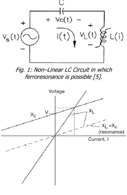
A Ferroresonance circuit includes series combination of saturable inductor, capacitor and linear resistor as shown in Fig.1. Ferroresonance occurs at a given frequency when one of the saturated core inductances matches with the capacitance of the network. The final effect is that there are several steady state overvoltage and overcurrent present. From the circuit in Fig. 1, let us assume that R is much smaller than |𝑋𝑐| and│XL│. Then Capacitive (XC) and
inductive (XL) reactance are assumed in full absolute
constant or linear, then, the magnitude of the current flowing in the circuit is approximately:
𝐼 = 𝑉
XL − Xc (1)
If Xc is to vary and hold R and XL at constant value.
When Xc = 0, the current flowing in the circuit is:
𝐼 = 𝑉
𝑋𝐿 (2)
When Xc is very large, the current becomes
negligible (negative value at the denominator) between these two extreme conditions, that is |𝑋𝑐|
=│XL│, the current becomes very large limited only
by the resistance R, then the equation becomes,
𝐼 = 𝑉
𝑅 (3)
This large current can lead to overvoltage [1]. However, if the value of XL varies assuming it is an
iron core transformer, then the possibility of XC to
match XL rises considerably. Figure 2 shows the
solution to the linear circuit. The intersection between the inductive reactance XL line and the capacitive
the voltage across the inductor (VL). However, when
XL is no longer linear, i.e it is a saturable inductor, the
reactance (XL) cannot be shown as a straight line. The
graphical result for non – linear circuit is shown in figure 3 [1].
Fig. 1: Non–Linear LC Circuit in which ferroresonance is possible [5].
Fig. 2: Graphical Solution for Linear Ferroresonance Circuit [6].
Fig. 3: Graphical Solution for Non- Linear Circuit [6].
From figure 3, it can be seen that there could be up to three intersection points between the capacitive reactance (XC) and inductive reactance (XL)
normal operation in the linear region of the magnetizing characteristics of the saturable inductor, where excitation current and flux are within the design limit.
At this point the inductor voltage (VL) is higher than
capacitance voltage (Vc). It is a non-ferroresonant stable operation point where steady state voltage across the inductor terminals. Intersection point “3” is a ferroresonant stable operation point in the saturation zone where VL is lower than Vc. This is a
capacitive situation, (XL-sat <Xc), where the flux
densities and excitation current are beyond the design limit. In contrast, the intersection point “2”, in the positive region, is unstable operating point since the source voltage increase follows a current decrease, thus violating the equilibrium theory [7].
3.UNDERGROUND CABLE DESCRIPTION Underground cables have the same basic parameters as overhead line: series, resistance, inductance, shunt capacitance and conductance. However, the value of the parameters and hence characteristics of cables differ significantly from those of overhead network for these reasons:
(i) The conductors in a cable are much closer to each other than are in the conductors of overhead lines.
(ii) The conductors in a cable are surrounded by metallic bodies such as shields, lead or aluminium sheets and steel pipe.
(iii) The insulating material between conductors in a cable is usually
impregnated paper, low viscosity oil or inert gas [8].
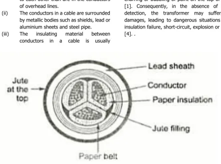
The cable connecting the station is a shielded single core three-phase underground cable of phase-to-phase voltage 11 kV rms value. A sectional view of the cable trefoil configuration is as shown in the figure.
The selected cable is a coaxial system made up an aluminium central conductor (core) in which the phase current circulates. This conductor is surrounded by an insulating envelope (paper insulation). An outside lead sheath plays at the same time the role of a references electrode, an evacuating path of the short-circuit current, a sheath barrier and a mechanical protection. The sheath is covered with an external synthetic material in polyethylene (black EP) [9].
4. SYMPTOMS OF FERRORESONANCE 4.1.Transformer heating and loud noise One of the reported symptoms of the high magnetic field is due to stray flux heating in parts of the transformer where magnetic flux is not expected. Since the core is saturated continuously, the magnetic flux will find its way into the tank wall and other metallic parts. One possible side effect is the charring or bubbling of paint on the top of the tank [1]. Consequently, in the absence of a quick detection, the transformer may suffer severe damages, leading to dangerous situations such as insulation failure, short-circuit, explosion or even fire [4]. .
4.2.High sustained overvoltage
One of the most of the precarious consequences of the ferroresonant phenomenon is the damaging level of overvoltage that may lead the electrical system components (cables, switchgear, transformers and surge arresters) to a sudden failure with disastrous consequences. The most important factor to get to know the possible overvoltage level is the transformer winding connection. The magnitude of the overvoltage reported for grounded transformers rise up to 2.5 p.u. In contrast, the situation in ungrounded transformers may become more worrying, with 5 p.u. and higher magnitudes [4].
4.3.Electrical Equipment Damage
The other main component that has to cope with the ferroresonant threat is the surge arrester. The overvoltage levels and the energy involved under ferroresonant conditions may be too high to be absorbed reliably. Therefore, both sides of the transformer can be affected somehow and those arresters involving customer appliances and those located in the distribution network can too be affected. Accordingly, many end-user facilities can also be affected and even be seriously damaged, such as computer and other consumer appliances, office equipment, factory machines, etc. [4].
4.4.Power quality problems, due to the distortion of current and voltage waveforms. The high harmonic distortion of ferroresonant voltage and current waveforms usually lead the electric system to have several power quality problems. A good example of this would be flicker, as a consequence of the wild voltage fluctuation in figure 5. The customer circuit appliances that may be affected by this distorted voltage waveform may vary, from the light bulbs flicker to some electronic appliances, even shortening their expected life [4].
Fig. 5: Typical ferroresonant overvoltage [7].
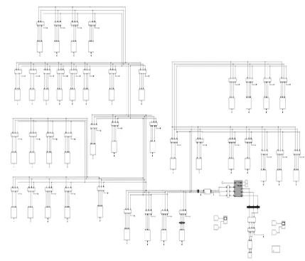
5. MODELLING AND SIMULATION OF THE INJECTION SUBSTATION, GARKI 1 SERVICE CENTRE, ABUJA
Modelling and simulation for ferroresonance in distribution network with appropriate circuit parameters obtained from the station under study were realized using MATLAB-SIMSCAPE is represented in the figure 6.
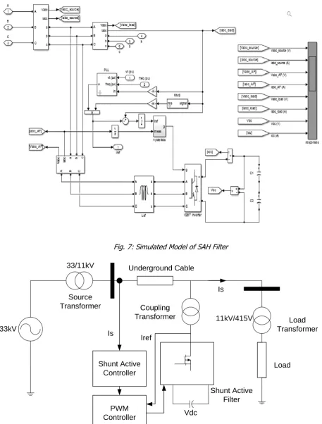
The simulated model of the Shunt Active Harmonic Filter designed and applied in this study as shown in the Figure 7 for the purpose of mitigating the effect of ferroresonance phenomenon (harmonics) in the network.
This Filter as shown in figure 7 is a device which generates the similar harmonic as generated from the source but out of phase by 180⁰. This Active filter measures the current supplied to the load and compares it with a set reference (a harmonic free current) and generates an error current. The objective of this filter is to ensure that this error current is minimal. To achieve this, a Phase Locked Loop (PLL) in the figure 7 generates a reference sinusoidal source current which is in phase and has the same root means square (rms) gain as the load current. It then compares the load current with this reference current in order to reduce this error. This generated current is then fed to a hysteresis controller. Hysteresis Current Control (HCC) technique is basically an instantaneous feedback current control method of Pulse Width Modulation (PWM), where the actual current continually tracks the command current within a hysteresis band.
Hysteresis band (HB) is the possible boundary of the compensating current. This current deviates between upper and lower hysteresis limits. Hysteresis current controller will generate pulses in such a manner that inverter output current will follow the reference current that generates gating current that would control the Insulated Gate Bipolar Transistor (IGBT) Inverter. IGBT inverter generate the error current between the load current and the reference current. This generated current by IGBT is 180° out of phase
with the source current, in an effort to cancel the harmonic present in the source. This active filter can be likened to a collection of individual active filters tuned to a particular cut-off frequency but connected in parallel. The Inductor connected to the IGBT provide the reactive component and the Vdc capacitors
𝐼𝐻= ∑ 𝐼𝑟𝑒𝑎𝑙+ 𝑗𝐼𝑟𝑒𝑎𝑐𝑡𝑖𝑣𝑒 𝑁
𝑖=0
(4)
Figure 8 shows the basic scheme of shunt active harmonic filter connected to the network through coupling transformer.
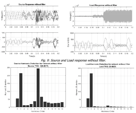
It is observed from Fig. 9 that before 0.06s, the waveforms of both Voltage and Current are smooth and accurate without any eruption. The Voltage is in the region is 10 kV before 0.06s while it is observed that after 0.06s, the ferroresonance effect appeared with disrupted amplitudes at high frequency values (harmonics) and then goes on until 0.1s when a large amplitude appears and it grows towards double the initial value at the source. At the load side, it is also observed that the voltage is at 10 kV (0.1*105) before
0.06s and rose to 25 kV at 0.06s, a higher amplitude of the voltage and current variation occur until 0.1s as a result of the capacitive nature of the underground cable. Charging and discharging of capacitive nature of the underground cable account for the jump
resonance from one steady state to another as it occurred in 0.06s, 0.1s, 0.14s and 0.18s.
Total Harmonic distortion is the summation of all harmonic components of the voltage or current waveform compared against the fundamental component of the voltage or current wave [10] and is given as:
𝑇𝐻𝐷 =√(𝑉2
2+ 𝑉32+ 𝑉42+ ⋯ … + 𝑉𝑛2)
𝑉1 × 100% (5)
The Total Harmonic Distortion in percentage for the network during ferroresonance were depicted in Fig. 10. The Total Harmonic Distortion of source current in the network without filter is 126.901% while that of load Total Harmonic Distortion for network without filter shown is 26.692%. This abruptly reduction in harmonic distortion was as a result of many resistive loads and transformer grounding that absorbed large amount of harmonics.
Fig. 7: Simulated Model of SAH Filter
33kV
Source Transformer
Load Transformer Coupling
Transformer Underground Cable
Shunt Active Filter Shunt Active
Controller
PWM Controller
Iref Is
Is
Vdc 33/11kV
11kV/415V
Load
Fig. 8: Shunt Active Filter connected to the line
6.FERRORESONANCE MITIGATION
The Ferroresonance phenomenon leads to distortion waveform (harmonics). It is found that this unwanted harmonic can increase the current in power system
It is also found that this harmonics distortion can result to dielectric stress which is dangerous for electrical equipment i.e failure, reduction in performance and breakdown of insulation in an underground cable.
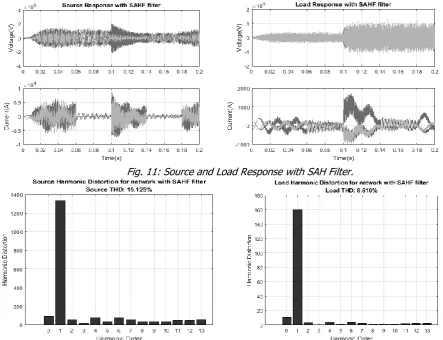
Due to these effects of ferroresonance observed as a result of high harmonic distortion content in the waveform, this phenomenon needs to be reduced to the manageable level to avoid stresses on equipment and enhancing safety of the system. The filter circuit in figure 6 was applied and the result is as shown in figure 11.
The Figure 11 shown the waveform generated after application of Shunt Active Harmonics filter. It is observed that it takes effect at exactly 0.06s started reducing the harmonics distortion at exactly the expected time. At 0.06s, it generated compensation current which is out of phase (180⁰) to the harmonic generated by ferroresonance in the system. At 0.1s, it generated higher opposite compensation current because of high harmonic generated by ferroresonance at that time and it stabilized the voltage to be nearly 11 kV. Any voltage above 11kV
is considered as overvoltage which is as a result of ferroresonance.
From the Charts in Fig. 12 the Total Harmonic Distortion for source reduces from 126.90% to 15.125% while that of the load reduces from 26.692% to 8.610%. This filter reduced the harmonic content by 88.081% at the source and 67.743% at the load. The percentage (%) reduction in Harmonic distortion for both the source and load were calculated from total harmonic distortion. Comparison of Total Harmonic Distortion (%) and percentage reduction for source and load before and after insertion of Shunt Active Harmonic Filter as shown in the Table 1.
Table 1: Total Harmonic Distortion in % Before and After SAH Filter
Source Load Before 126.901 26.692
After 15.125 8.610
% Reduction 88.081 67.743
Fig. 9: Source and Load response without filter.
Fig. 11: Source and Load Response with SAH Filter.
Fig. 12: Source and Load Harmonic Distortion with SAH filter
7.CONCLUSION
In this research work, the ferroresonance phenomenon are considered under the modelling of the Garki 1 service centre network of 33/11 kV in Abuja, Nigeria, using MATLAB/SIMSCAPE. It was also discovered that ferroresonance phenomenon can occur when the station breaker is open or during switching event. The effectiveness of shunt active harmonic filter for harmonic suppression during ferroresonance event which was determined through simulation result.
The reduction of total harmonic distortion content for the source and load from (126.901%, 15.125%) to (26.692%, 8.610%) respective was achieved. This represent about 88.0815% and 67.743% harmonic reduction for the source and load respectively. As such, the Shunt Active Harmonic filter if developed is recommended for implementation in the distribution network to suppress ferroresonance to manageable levels in Nigeria because the result (8.610% Total harmonic distortion) obtained complied with IEEE-519 standard of harmonic control [10].
8. REFERENCES
[1]. Santoso, S, Dugan, C. R and Nedwick, P. “Modeling Ferroresonance Phenomena in an Underground Distribution System,”
International Conference on Power Systems Transients (IPST), Rio de Janeiro, Brazil, June 24-28, 2001, pp 1-6.
[2]. Engdahl, G. “Ferroresonance in Power System: Literature Study,” Royal Institute of Technology, Stockholm, Sweden, number 457, November, 2017.
[3]. Valverde, V. et al. “Behavioral patterns in voltage transformer for ferroresonance detection”, Electrotechnical Conference (MELECON), 16th IEEE Mediterranean, March 25-28, 2012, pp 1-4.
[4]. Buigues, G et al. “Ferroresonance in three– phase power distribution transformers: Sources, consequences and prevention,”19th International Conference on Electricity Distribution, Vienna, Spain, 2007, pp 1-4. [5]. Ferracci, P. “Ferroresonance”. Cahier
[6]. Abdul-Malek, Z, Mehranzanir, K, Salimi B and Afrouzi, H. N “Investigation of ferroresonance mitigation Techniques in voltage Transformer using ATP-EMTP Simulation” Jurnal Teknologi, University Teknologi, Malaysia, Vol. 64, Number 4, October 2013, pp 85-95.
[7]. Ta-Peng, T and Chia-Ching, N. “Analysis of ferroresonant overvoltage at Maanshan Nuclear Power Station in Taiwan”. IEEE Transactions on power delivery, Vol. 21, No 2, 2006, pp 1006-1012.
[8]. Prabha, K. Power System Stability and Control, McGraw-Hill Inc., United State of America, 1994.
[9]. Aloui, T, Ben Amar, F and Abdallah, H. H “ Modelling of a three-phase underground power cable using the distributed parameters approach” 8th Intermational Multi-conference on Systems, Signals and Devices, Vol.1, 2011, pp 411-416.
![Fig. 5: Typical ferroresonant overvoltage [7].](https://thumb-us.123doks.com/thumbv2/123dok_us/9983106.1986620/4.595.55.279.638.742/fig-typical-ferroresonant-overvoltage.webp)