The 3D Passive Position Research for
Three-Element Array in 0~359°
ZHENG Enming
University of Chinese Academy of Science, Beijing, China Email:[email protected]
CHEN Xinhua and SUN Changyu
Institute of Acoustics, Chinese Academy of Science, Beijing, China Email:[email protected]
Abstract—Three-element array is often used for measuring the distance between the object and the reference element. Cooperating with other devices or increasing the number of elements, the three-element array may achieve 3D (3D: three-dimensional) passive position. To the problem of 3D passive position of three-element array, this paper provides a method achieving three-dimensional passive position based on the underwater acoustic channel propagation characteristics in 0~359°. At the same time, the method can solve the y-axis fuzzy direction of the linear three-element array without prior knowledge. The numerical analysis and simulation show that this paper can well complete three-dimensional passive position, especially
for the shallow watershort-range target.
Index Terms—three-element array, underwater acoustic channel, three-dimensional passive position
I. INTRODUCTION
Because the active location need transmitter signal equipment and is easy exposure, the passive position technology of underwater target becomes one of the hot issues in sonar technology. The typical passive position method is achieved by measuring TDD (TDD: The time delay difference) of differential elements receiving signals [1]-[7]. But three-element array is used for the two-dimensional position [1]-[7], and doesn’t relate to the 3D passive position of targets, especially for the line three-element array [6]. In this paper, we can achieve 3D passive position of three-element array by the propagation characteristics of the underwater acoustic channel [8]-[13] and virtual element. The method can solve the fuzzy direction of the y-axis [14] comparing to the line three-element array without prior knowledge, and also reduces the installation difficulty of the line array. This paper achieves high-precision 3D passive position through the correlation method and interpolation
Manuscript received December 9, 2012; revised May 20, 2013. This work is supported by National Ocean Community Foundation of China (No. 60675025).
method [15], [16].The TDD between virtual element and real element is distinguished by the expert system [17]. Numerical analysis and simulation show that the method can achieve 3D passive position in 0~359° , especially for shallow water short-range targets.
II. NON-LINEAR THREE-ELEMENT ARRAY POSITION PRINCIPLE AND ALGORITHM
A. Underwater Acoustic Channel Propagation Characteristics
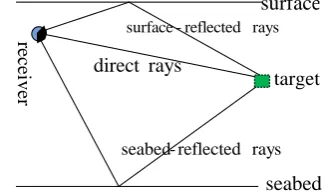
Because of multi-path effect of underwater acoustic channel, the target radiating signals may contain the direct rays, the surface-reflected rays, the seabed- reflected rays, the surface seabed-reflected rays, and the seabed surface-reflected rays when they arrive the receiving elements [8]-[13]. This paper will give a method that can achieve 3D passive position of three-element array by the propagation characteristics of the underwater acoustic channel and virtual element. Fig. 1 is sound rays Fig that contains the direct rays, the surface-reflected rays, the seabed- reflected rays.
surface
seabed target
receiver
rays direct
rays reflected -seabed
rays reflected -surface
Figure 1. Sound rays Fig of underwater acoustic channels
According to Fig. 1, we can use the Eq. (1) denote the relationship between target radiating signals and receiver receiving signals.
1
( ) N ( ) ( ), 1, 2,3
j i i j ij
x t
A s t tt j (1)where, ( ) j
and ij
A denotes the element
j
receiving the amplitudevalue of the ray
i
,andt
ij denotes the time delay of theelement
j
receiving the rayi
, and s t( )denotes thetarget radiating signals, and (tti) denotes the response function of the underwater acoustic channels, and
N
denotes the number of rays that arrive the receiver array elements through underwater acoustic channels.B. Non-linear Three-element Array Position Principle
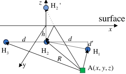
According to the section A, this paper provides a virtual element by the middle element through the sea surface. The virtual element receiving signal is the surface-reflected signal of the middle element. Fig. 2 is the three dimensional position schematic diagram of the three-element array based on underwater acoustic channel propagation characteristics.
A( , , )
x y z
3
H
1H
2H
2H '
h
d
R
y
x
z
d
d
surface
Figure 2. The 3D passive position schematic diagram of the three-element array in 0~359°
where, A( , , )x y z denotes the target, and 1
H ( , ', )d d h ,
2
H (0, 0, )h ,H (3 d, 0, )h denote three receiving elements, and H '(0, 0,2 h) denotes virtual element of H (0, 0, )2 h , and d, d', h denote coordinate parameters, and R denotes the distance between A( , , )x y z and
2
H (0, 0, )h . We can use (2.1)—(2.4) denote the distance between A( , , )x y z and
2
H (0, 0, )h , H ( , ', )1 d d h ,
2
H '(0, 0,h), H (3 d, 0, )h in Eq.(2) 2 2 2 2
2 2 2 2
21
2 2 2 2
23
2 2 2 2
22
( ) , (2.1)
( ) ( ') ( ) ( ) , (2.2)
( ) ( ) ( ) , (2.3)
( ) ( ) , (2.4)
x y z h R
x d y d z h R c
x d y z h R c
x y z h R c
(2)
where,21 ,22,23 denote the time delay difference between H ( , ', )1 d d h , H '(0, 0,2 h) , H (3 d, 0, )h and H (0, 0, )h , and
c
denotes the sound speed. The partAccording to the Eq. (2) and Eq. (3), we can get the coordinate value of x-axis, y-axis, z-axis as Eq. (4).
2 2
23 23
2 2 2 2
21 23 21 23
2
22 22
2
, (4.1) 2
2 ' 2 ( )
, (4.2) 2 '
2
, (4.3) 4
R R R d
x
d
d d R R R R R
y
d
R R R
z h (4)
We can use (2.1), (4.1), (4.3), (4.3) solve the distance R as the Eq. (5), (6).
whenA60:
1 2 3 4 5
6
A A A A A
R
A
(5)
whenA60:
1 2 3 4 5
6
A A A A A
R
A
(6)
where,A1,A2,A3,A4,A5,A6are shown as Eq.(7) .When
Ris known , we can useRand Eq. (4.1), (4.3), (4.3) solve the three-dimensional coordinates of the target.
2
1 23 4 23 2 3
1 2 2 2
2 2 2
1 2 4
2 2 2 2
2 2 2
3 23 22
3 2 2 2
2 2 2 4
2 2 2 2
2 2
2 3 4 22
5 1 23
2 2 2 2 2
2 2 2 2 2 2
3 22
6 23
4 2 '
' 4 1
4 ' 4
'
' '
'
2 4
'
2 ' 2 '
2 2
B R B R B B
A
d h d
B B B
A
d d h
B R R
A
d d h
A d h d
B B h d B R d d
A B R h d
B d h d R d
A h d R d h d
(7) where, 1
B,B2,B3,B4are shown as Eq. (8).
2 2
1 23
2 2 2 2
2 23 21
3 23 21
2 2
4 22
' 2
2( )
4
B R d
B R R d d
B R R
B R h
(8)
Similarly, we can image the virtual element 1 H ' ,
3
H ' from the elementH ,1 H based on the sea surface. 3 Then according to the Eq. (5) to (8), we can get
A( , , )x y z .
We can calculate the differential coefficient for (4.1), (4.3), (4.3), then obtain the position error as the Eq. (9).
2
23 23 23 23 23
2
23 23 21 21 21 23 21 23
2 2 2
2 2 2
2 2
2 2 2 2 2
2 '
2 2 ( ) '
'
R R R R R d R R R d d
x
d
d d R R R R R R R R R R
y
d
d R R R R R d
III. THE NUMERICAL ANALYSIS
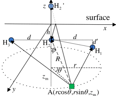
In order to verify that the method can realize 3D passive position in 0~359° , we use Fig. 3 as the simulated target track for numerical simulation.
3
H
1
H
2H
2H '
h
d
R
y
x
z
d
d
m
A( cos , sin ,
r
r
z
)
mz
r
surface
Figure 3. The figure of simulated target track
Where, rRsin
denotes the horizontal radius of the target, and cosm
z R denotes depth of target, and R denotes the distance between target and H , and 2
denotes the pitch angle of target, and denotes azimuth of target.A.3D Passive Position in 0 ~ 359
In order to simulate position effects of the actual target, in this paper, we use 2 ~ 5 kHz white noise as target
radiating signal. Target radiating signal becomes the direct rays and the sea surface-reflected rays arriving the receiver. The amplitude of the direct rays and the sea surface-reflected rays is calculated by spherical wave propagation characteristics. The TDD between the elements is calculated by path difference between the target and each element. The signal-to-noise ratio is
6 dB
SNR , and sound speed is c1500 m/s, and the sample rate is fs250 kHzof target radiating signal, then the receiver’s sample rate isfs25 kHz.So original TDD error is
2 μs, but the receiver’s TDD error is
20 μs if only using correlation method. We can use correlation method and10 times frequency domain interpolation get the high- precision TDD[15], [16].s C E[ ( ) ( )]
FC fft(C ) , 2; 1, 2, 3 C ifft(FC ,10 )
i j i j
i j i j
i j i j
x x x t x t
x x x x i j
x x x x f
(10)
Where,Cx xi j is the result of the correlation between i
element receiving signalx ti( )and jelement receiving
signal ( ) j
x t , and E[] is the mathematical expectation
function, andfft()is the Fourier transform function, and ifft() is the inverse Fourier transform function. So the accuracy ofC
i j
x x is increased by 10 times comparing the accuracy of Cx xi j.Through the expert system [17], we can obtain the time delay differences21,23,22.
In order to observe the details of the target position, Fig. 4 shows the result of 3D passive position by 100 times independent statistics when r500 m.
Figure 4. The position results when d15,h10,d' 2 ,r500 m, 30 ~ 150, 210 ~ 330
According to Fig. 4, we can find that the method can achieve the 3D passive position in 0~359° , because the projection aperture in the y-axis direction is relatively small, the position accuracy is not high in the x-axis direction. But we can use cross array solve the low position accuracy in the x-axis direction.
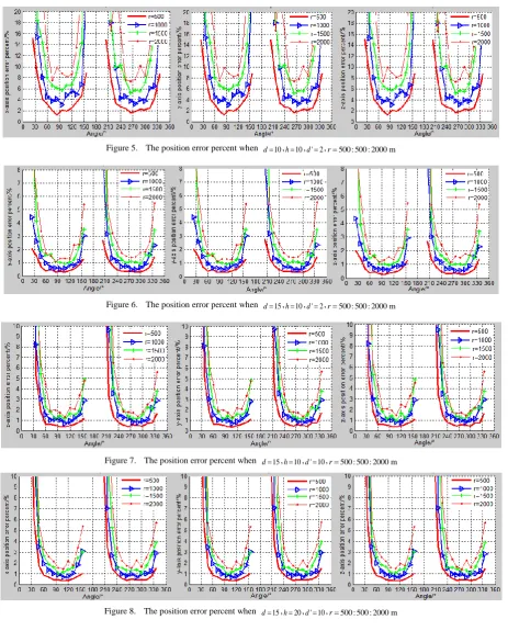
In order to show that the elements position has impact on 3D passive position results, we will give the numerical simulation results from the following four aspects.
1) Assuming the coordinate parameters are d10, 10
h , ' 2d , Fig. 5 is position errors.
2) Assuming the coordinate parameters are d15, 10
h , ' 2d , Fig. 6 is position errors.
3) Assuming the coordinate parameters are d15, 10
h , ' 10d , Fig. 7 is position errors.
4) Assuming the coordinate parameters are d15, 20
Figure 5. The position error percent when d10,h10,d' 2 ,r500 : 500 : 2000 m
Figure 6. The position error percent when d15,h10,d' 2 ,r500 : 500 : 2000 m
Figure 7. The position error percent when d15,h10,d' 10 ,r500 : 500 : 2000 m
Figure 8. The position error percent when d15,h20,d' 10 ,r500 : 500 : 2000 m
According to the results of Fig. 5 — Fig. 8, we can get the following conclusions:
1) The position accuracy becomes worse as the distanceRbecomes larger. Especially,when d is small (comparing Fig. 5 with Fig. 6).
2) Because the element H is located in the fourth 1
quadrant in the simulation, as d' becomes larger, the 2,4 quadrants position accuracy becomes better, and the
3) The parameter hhas a small impact on the position accuracy (comparing Fig. 7 with Fig. 8).
4) The position accuracy of x-axis direction and y-axis direction becomes better asd becomes larger, especially for shallow water short-range targets (comparing Fig. 5 with Fig. 6).
results prove that the parameter d in x-axis direction has a great impact on position accuracy, so high position accuracy need large d. According to spatial correlation radius of noise signal and convenient installation,d is not too large.
IV. CONCLUSION
This paper uses multi-path effect of underwater acoustic channel propagation characteristics and virtual element to obtain the 3D passive position formula of the non-linear three-element array, and solve the fuzzy direction of the y-axis without prior-knowledge. Numerical simulation has verified that this method can effectively achieve 3D passive position in 0~359° especially for shallow water short-range targets in
30 ~150鞍 and 210 ~330鞍 . At the same time, we can fuse the redundant data to achieve better position. But to the problem of x-axis direction being not good in this paper, we can increase the element in y-axis to solve. We need further explore for three-element array achieving same precision in0~359°.
REFERENCES
[1] Q. H. Li, Digital Sonar Design Theory, Hefei: Anhui Education Publisher, 2003, pp. 350-359.
[2] W. Zhou, L. J. Men, and J. D. Mei, “Experimental research on passive near field ranging of a three-sensor array in shallow water,” Journal of Harbin Engineering University, vol. 30, no. 5, pp. 547-551, 2009.
[3] W. Zhou, J. Y. Hui, and J. D. Mei, “Experiment of passive ranging for three-sensor array in shallow sea and post processing,” ACTA ACUSTICA, vol. 34, no. 3, pp. 217-222, 2009. [4] W. Zhou, “Study and analysis of three sensor array passive ranging of near target in shallow water,” M. Eng. dissertation, Harbin Engineering University, 2008.
[5] J. Liang, Y. Yu, and X. Y. Yan, “Passive position theory and validating of ternary array,” Ship Electronic Engineering, vol. 29, no. 5, pp. 144-145, 2009.
[6] L. P. Wei, Y. Chen, and G. Chen, “Application of unequally-spaced and non-linear three-hydrophone array in underwater acoustic coplanar target passive localization,” Applied Acoustics, vol. 28, no. 6, pp. 447-453, 2009.
[7] L. Badriasl, K. Dogancay, and S. Arulampalam, “3D passive localization in shallow water using bearing and multipath time-delay measurements,” ISSNIP, pp. 473-478, 2011.
[8] D. B. Kilfoyle and A. B. Baggeroer, “The state of the art in underwater acoustic telemetry,” IEEE Journal of Oceanic Eng., vol. 25, no. 1, pp. 4-27, 2000.
[9] Newell O. Booth, Ahmad T. Abawi, and Phil W. Schey, “Detectability of low-level broad-band signals using adaptive matched field processing with vertical aperture arrays,” IEEE Journal of Oceanic Engineering, vol. 25, no. 3, pp. 296-313, 2000.
[10] L. Wei, F. Xu, and H. X. Sun, “Research and simulation on underwater acoustic communication channel,” Technical Acoustics, vol. 27, no. 1, pp. 25-29, 2008.
[11] Y. Lan, X. H. Zhang, and X. Xiong, “Modeling and simulation on shallow water acoustic multi-path channels,” SHIP SCIENCE
AND TECHNOLOGY, vol. 28, no. 9, pp. 120-122, 2010.
[12] J. Y. Hui and X. L. Sheng, Underwater Acoustic Channel, 2nd edited, Beijing: National Defense Industry Press , 2007. [13] J. Yang and F. Xu, “A new method for the underwater acoustic position: virtual short baseline position,” in Proc. ICIEA 2009, pp.3910-3912.
[14] Y. H. Wei, X. H. Chen, and H. B. Yu, “A method for underwater 3-D passive,” Applied Acoustics, vol. 27, no. 4, pp. 268-272. 2008.
[15] L. J. Chen, “Auto-Correlation multipath time delay estimation and its experimental results,” Journal of Southeast University, vol. 28, no. 1, pp. 18-23, 1998.
[16] Q. Huang, “Bispectrum time delay estimating based on correlation,” ACTA ACUSTICA, vol. 28, no. 1, pp. 57-60, 2003. [17] J. Yang, “The studies on passive tracing of underwater moving
target,” D. Eng. dissertation, Harbin Engineering University, 2007.
ZHENG Enming (1985 - ), received the B.S. degree in 2009, from Harbin Engineering University. Now, He is currently working toward the Ph.D degree of the Institute of Acoustics, Chinese Academy of Sciences (IACAS), Beijing, China.
His research interests lie in signal processing and detection, signal processing for underwater acoustic communications and positions. Alpha
CHEN Xinhua (1978 - ), received the B.S. degree in 1999 and the Ph.D. degree in 2004, from Harbin Engineering University, Harbin, China. He read postdoctoral from 2004 to 2006 in the Institute of Acoustics, Chinese Academy of Sciences (IACAS), Beijing, China.
He has dedicated to the research the development of vector hydrophone, signal processing technology of sound pressure and velocity, array engineering technology, array signal processing techniques, underwater acoustic positioning technologies as well as the sound of water against technology and other aspects of the work.
SUN Changyu (1954 - ), graduated from Peking University, Department of Electronics, underwater acoustic physics in 1981, then was assigned to work at the Institute of Acoustics, Chinese Academy of Sciences and studied in RIKEN, Japan in 1992-1994.
Now he is the Director, and researcher of the Institute of Acoustics, Chinese Academy of Sciences, the water acoustics technical director researchers, doctoral tutor, fellow of the Acoustical Society of China, and Japan Science and Technology Exchange Association, Signal Processing Industry Association governing.