Volume-7 Issue-1
International Journal of Intellectual Advancements
and Research in Engineering Computations
Fuzzy controlled based PV Statcom for solar forms
E.Edison Selvaraj
1, M.Kumar
2, M.Suriyamoorthy
2, M.Karthick
2, E.Ambetkar
21
Assistant Professor/EEE
2UG Scholar
Department of EEE, The Kavery Engineering College, Salem.
ABSTRACT
Power system performance may be defined as the performance study of power system during normal operating condition, fault condition and after removal of fault. A novel concept of utilizing a photovoltaic (PV) solar farm inverter as STATCOM, called PV-STATCOM using fuzzy controller is proposed in this paper, for improving stable power transfer limits of the interconnected transmission system. During daytime, the inverter capacity left after real power production is used. During different operating conditions system has different real and reactive power flow which is required to be controlled to enhance the system power transfer capability, transient stability and reduce the losses in the system. For this purpose, recent trend is the use of FACTS control devices. The PV-STATCOM improves the stable transmission limits substantially in the night and in the day even while generating large amounts of real power. The main function of the LCL filter is to reduce high-order harmonics on the output side; however poor design may cause a distortion increase. Here we are using the fuzzy controller compared to other controllers i.e. The fuzzy controller is the most suitable for the human decision-making mechanism, providing the operation of an electronic system with decisions of experts. Power transfer increases are also demonstrated in the same power system for: 1) two solar farms operating as PV-STATCOMs and 2) a solar farm as PV-STATCOM and an inverter-based wind farm with similar STATCOM controls. By using the fuzzy controller for a nonlinear system allows for a reduction of uncertain effects in the system control and improve the efficiency. By using the simulation results we can analyze the proposed method.
Index Terms:
Damping control, Flexible ac transmission systems (FACTS), inverter, Photovoltaic solar power systems, Fuzzy logic controller, Reactive power control, STATCOM, Transmission capacity, Voltage control, Wind power systemINTRODUCTION
The main sources of energy sources of renewable energy are solar, wind, rain, tides, waves and geothermal heat. These renewable energy sources are providing backup in electricity generation and rural (off-grid) energy services. Though these renewable energy sources are not much cost effective in comparison to traditional conventional energy sources. FLEXIBLE AC transmission system being increasingly considered to increase the avail-stem (FACTS) controllers able power transfer limits/capacity (ATC) of existing transmission lines [1]–[4], globally. New
research has been reported on the nighttime usage of a photovoltaic (PV) solar farm (when it is normally dormant) where a PV solar farm is utilized as a STATCOM–a FACTS controller, for performing voltage control, thereby improving system performance and increasing grid connectivity of neighboring wind farms. Solar Photovoltaic is a system which uses solar panels for converting solar energy to electrical energy. Photovoltaic effect is a phenomena in which electrons are excited into a higher state of energy by photons of light due to which these electrons act as a charge carrier for the flow of current. New
voltage control has also been proposed on a PV solar farm to act as a STATCOM for improving the power transmission capacity. This paper proposes novel voltage control, together with auxiliary damping control, for a grid-connected PV solar farm inverter to act as a STATCOM both during night and day for increasing transient stability and consequently the power transmission limit. This paper describes about a technology which utilizes PV solar farm as a STATCOM during night time. This technology of utilizing a PV solar farm as a STATCOM is called “PV-STATCOM.” It utilizes the entire solar farm inverter capacity in the night and the remainder inverter capacity after real power generation during the day, both of which remain unused in conventional solar farm operation. Similar STATCOM control functionality can also be implemented in inverter-based wind turbine generators during no-wind or partial wind scenarios for improving the transient stability of the system. In this paper a simple open-loop control method has been presented such that PV solar plant could be used as STATCOM, in dark periods without sunlight, to control the voltage or for load reactive power compensation and voltage control. This work improves the power factor, which enhances the efficiency of the line and reduces the losses of the line due to reduction in load current. This paper also presents the comparative simulation study of STATCOM with PI controller and fuzzy controllers and hence shows that performance of STATCOM is better with fuzzy controller in comparison with PI controller.. The improvement in the stable power transmission limit is investigated for different combinations of STATCOM controllers on the solar and wind farm inverters, both during night and day. [1-3]
Need of renewable energy system
With high population growth and economic development in the world, there is a very high demand for energy. Traditional fossil sources such as oil, coal are costly and have a serious pollution to the environment. To have sustainable growth and social progress, it is necessary to meet the energy need by utilizing the renewable energy resources like wind, biomass, energy, co-generation, etc. In sustainable energy system,
energy conservation and the use of renewable source are the key paradigm. The need to integrate the renewable energy like Fuel cell energy into power system is to make it possible to minimize the environmental impact on conventional plant. There has been an extensive growth and quick development in the exploitation of Fuel cell energy in recent years. The individual units can be of large capacity up to 2 MW, feeding into distribution network, particularly with customers connected in close proximity. Today, more than 28,000 Fuel cell generating turbine are successfully operating all over the world. [4-6]
In the fixed-speed Fuel cell turbine operation, all the fluctuation in the Fuel cell speed are transmitted as fluctuations in the mechanical torque, electrical power on the grid and leads to large voltage fluctuations. During the normal operation, Fuel cell turbine produces a continuous variable output power. These power variations are mainly caused by the effect of turbulence, Fuel cell shear, and tower-shadow and of control system in the power system. Thus, the network needs to manage for such fluctuations. The power quality issues can be viewed with respect to the Fuel cell generation, transmission and distribution network, such as voltage sag, swells, flickers, harmonics etc. However the Fuel cell generator introduces disturbances into the distribution network. [7-10]
One of the simple methods of running a Fuel cell generating system is to use the induction generator connected directly to the grid system. The induction generator has inherent advantages of cost effectiveness and robustness. However induction generators require reactive power for magnetization. [11, 12]
proposed for improving the power quality which can technically manages the power level associates with the commercial Fuel cell turbines.
Scope of the project
The scope of the project is to have sustainable growth and social progress, it is necessary to meet the energy need by utilizing the renewable energy resources like wind, biomass, energy, co-generation, etc In sustainable energy system, energy conservation and the use of renewable source are the key paradigm. The need to integrate the renewable energy like Fuel cell energy into power system is to make it possible to minimize the environmental impact on conventional plant. The integration of wind-energy energy into existing power system presents a technical challenges and that requires consideration of voltage regulation, stability, power quality problems. For that this project should be given the solution
Steps of implementation
In the present work shunt active filter & battery energy storage system are considered to achieve the objectives of the compensation of harmonic current generated by a Non-Linear load & maintained stand alone supply for the critical load.
The objectives of the project are:
To simulate the Micro Wind-Energy power generation unit with battery energy storage to provide uninterrupted power supply to critical load by using MATLAB.
To maintain Unity power factor and power quality at the point of common coupling bus as per IEC-61400-21.
Unity power factor and power quality at the point of common coupling bus.
Real and reactive power support from Fuel cell generator and batteries to the load.
Stand-alone operation in case of grid failure.
Existing system
In this project we used harmonics reduction by using harmonics compensation techniques by using PI controller .it so not adaptive control so error solution will not be accurate. And response time for compensating harmonics is high. When a voltage and/or current waveform is distorted, it causes abnormal operating conditions in a power system such as:
Voltage Harmonics can cause additional heating in induction and synchronous motors and generators.
Voltage Harmonics with high peak values can weaken insulation in cables, windings, and capacitors.
Voltage Harmonics can cause malfunction of different electronic components and circuits that utilize the voltage waveform for synchronization or timing.
Current Harmonics in motor windings can create Electromagnetic Interference (EMI).
Current Harmonics flowing through cables can cause higher heating over and above the heating that is created from the fundamental component.
Current Harmonics flowing through a transformer can cause higher heating over and above the heating that is created by the fundamental component.
Current Harmonics flowing through circuit breakers and switch-gear can increase their heating losses.
RESONANT CURRENTS which are created by current harmonics and the different filtering topologies of the power system can cause capacitor failures and/or fuse failures in the capacitor or other electrical equipment.
Disadvantages
For this system cant eliminates 3rd and 9th harmonics in active power filters
Delay compensation is not considered
Proposed method
Delay compensator has include advancing angle of the current regulator output voltage as well as discrete current regulator design. Fuzzy controller has influencing in this system for compensate the Harmonics. This paper presents a method to identify power system impedance in real-time using signals obtained from grid connected power electronic converters. The proposed impedance estimation has potential applications in Fuel cell/distributed energy systems, STATCOM, and solid state substations.
The design of STATCOM parameters are considered an optimization problem according to
the time domain-based objective function solved by a fuzzy controller that has a strong ability to find the most optimistic results associated with small disturbances imposed by power converters and determine the net impedance back to the source. A data capture period of 5 ms is applied to an accurate impedance estimation which provides the possibility of ultra fast fault detection The paper describes how the proposed method would enhance the distributed generation operation during faults.
Advantages of proposed system
3rd and 9th harmonics can be eliminated in proposed system.
Possible to compensate the harmonics up to NYquist level.
Working and reliability
Power quality and reliability cost the industry large amounts due to mainly sags and short-term interruptions. Distorted and unwanted voltage wave forms, too. And the main concern for the consumers of electricity was the reliability of supply. Here we define the reliability as the continuity of supply. As shown in figure: 3.1, the problem of distribution lines is divided into two major categories. First group is power quality, second is power reliability. First group consists of harmonic distortions, impulses and swells. Second group consists of voltage sags and outages. Voltage sags is much more serious and can cause a large amount of damage. If exceeds a few cycle, motors, robots, servo drives and machine tools cannot maintain control of process.
PV array based statcom simulation
The PV based STATCOM modelled in chapter 3 as shown in figure 5.9, is used here for validating its ability in increasing the system stability during fault condition.
System description
Power quality and reliability
Both the reliability and quality of supply are equally important. For example, a consumer that is connected to the same bus that supplies a large motor load may have to face a severe dip in his supply voltage every time the motor load is switched on. In some extreme cases even we have to bear the black outs which is not acceptable to the consumers.
There are also sensitive loads such as hospitals (life support, operation theatre, and patient database system), processing plants, air traffic control, financial institutions and numerous other data processing and service providers that require clean and uninterrupted power. In processing plants, a batch of product can be ruined by voltage dip of very short duration. Such customers are very wary of such dips since each dip can cost them a substantial amount of money.
Operation
A STATCOM is build with Thyristors with turn-off capability like GTO or today IGCT or with more and more IGBTs. The static line between the current limitations has a certain
steepness determining the control characteristic for the voltage. The structural and operating characteristics shown in the Figure: 3.3.The STATCOM is connected to the power system at a PCC (point of common coupling), through a step-up costep-upling transformer, where the voltage-quality problem is a concern. The PCC is also known as the terminal for which the terminal voltage is UT. All required voltages and currents are measured and are fed into the controller to be compared with the commands.
The controller then performs feedback control and outputs a set of switching signals (firing angle) to drive the main semiconductors witches of the power converter accordingly to either increase the voltage or to decrease it accordingly.
A STATCOM is a controlled reactive-power source. It provides voltage support by generating or absorbing reactive power at the point of common coupling without the need of large external reactors or capacitor banks. Using the controller, the VSC and the coupling transformer, the STATCOM operation is illustrated in Figure: 3.3.
STATCOM operation in a power system
The charged capacitor Cdc provides a DC voltage, Udc to the converter, which produces a set of controllable three-phase output voltages, U in synchronism with the AC system. The synchronism of the three-phase output voltage with the transmission line voltage has to be performed by an external controller. The amount of desired
The reactive power exchange between the converter and the AC system can also be controlled. This reactive power exchange is the reactive current injected by the STATCOM, which is the current from the capacitor produced by absorbing real power from the AC system.
Where, Iq is the reactive current injected by the STATCOM
UT is the STATCOM terminal voltage
Ueq is the equivalent Thevinen‟s voltage seen by the STATCOM
If the amplitude of the output voltage U is increased above that of the AC system voltage, UT, a leading current is produced, i.e. the STATCOM is seen as a conductor by the AC system and reactive power is generated. Decreasing the amplitude of the output voltage below that of the AC system, a lagging current results and the STATCOM is seen as an inductor. In this case reactive power is absorbed. If the amplitudes are equal no power exchange takes place.
Fig. 3.4 Phasor diagrams for STATCOM applications.
A practical converter is not lossless. In the case of the DC capacitor, the energy stored in this capacitor would be consumed by the internal losses of the converter. By making the output voltages of the converter lag the AC system voltages by a small angle, δ, the converter absorbs a small amount of active power from the AC system to balance the losses in the converter. The diagram in Figure: 3.4 illustrates the phasor diagrams of the voltage at the terminal, the converter output current and voltage in all four quadrants of the PQ plane.
RESULTS AND DISCUSSIONS
Performance analysis of grid power
A critical load is considered as a nonlinear load for the simulation of the system. The
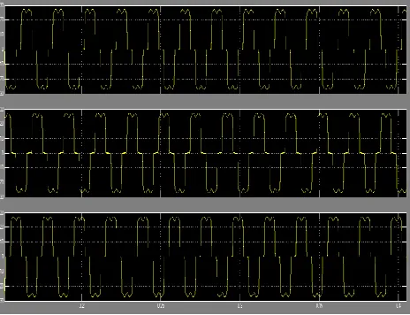
Fig 6.1. Simulated waveforms for compensation of harmonic current drawn by six pulse Rectifier. (a) DC Bus voltage
During this mode the inverter will support the critical load in the absence of source voltage. Due to the unavailability of source, the inverter will supply the full load current in this duration. Fig 6.1 Shows the DC bus voltage and R phase load, converter and grid current before and after harmonic compensation
Conclusion and future enhancements
The proposed micro-Fuel cell energy conversion scheme with battery energy storage, with an interface of inverter in current controlled mode for exchange of real and reactive power support to the critical load. The hysteresis current controller is used to generate the switching signal for inverter in such a way that it will cancel the harmonic current in the system. The exchange of Fuel cell and energy power is regulated across the dc bus having energy storage and is made available under the steady state condition. This also allows the real power flow during the instantaneous demand of the load. The scheme maintains UPF and also harmonic free source current at PCC in the distributed network. The
suggested control system is suited for rapid injection or absorption of reactive/real power flow in the power system. The battery energy storage provides rapid response and enhances the performance under the fluctuation of wind-energy output and improves the voltage stability of the system.
This scheme is providing a choice to select the most economical real power for the load amongst the available wind-battery-conventional resources and the system operates in power quality mode as well as in a stand-alone mode. Thus the proposed scheme in the grid connected system fulfils the power quality requirements and maintains the grid voltage free from distortion and harmonics.
Future enhancements
The proposed a STATCOM control scheme for grid connected hybrid Fuel cell and energy power energy system to improve power quality is using for conventional control of PID controller, which is compensate critical load and reactive power demand.
REFERENCES
[1]. M. A. H. El-Sayed, "Substitution Potential of Wind Energy in Egypt", International Journal of Energy Policy, 30, 2002, 681- 687,.
[3]. E. Muljadi and C.P. Butterfield, “Dynamic Model for Wind Farm Power Systems,” Global Wind Power Conference, Chicago, Illinois, 2004.
[4]. J.J.Brey, A. Castro, E. Moreno and C. Garcia, "Integration of Renewable Energy Sources as an Optimized Solution for Distributed Generation," 28th Annual Conference of the Industrial Electronics Society 4, 2002, 5-8.
[5]. F. De Campos, A. A. Penteado," Wind Energy Generation Simulation with Asynchronous Generator Connected to ENERSUL distribution System", IEEE/PES Transmission and Distribution Conference and Exposition: Latin America (IEEE Cat. No. 04EX956), 2004, 149-154.
[6]. R.Teodorescu, F. Blaabjerg, M. Liserre and A.V. Timbus, „Overview of Control and Grid Synchronization for Distributed Power Generation Systems‟, IEEE Transactions on Industrial Electronics, 53, 2006, 1398-1409. [7]. M.H. Nehrir, C. Wang and S.R. Shaw, “Fuel Cells: Promising Devices For Distributed Generation”, IEEE
Power and Energy Magazine, 4(1), 2006, 47-53.
[8]. M.M.A. Mahfouz, A. M.Amin and E. Yousef ,”Improvement the Integration of Zafarana Wind Farm Connected to Egyptian Unified Power Grid”, UPEC 2011, Soest, Germany, 2011, 5-8.
[9]. EG&G Technical Services, Inc., Fuel Cell Handbook (Seventh Edition), U.S. Department of Energy Office of Fossil Energy, National Energy Technology Laboratory P.O. Box 880, Morgantown, West Virginia 2004, 26507-0880.
[10]. S. Nawar,”Design and Control of Fuel Cell for Transportation Application”, M Sc Thesis, Cairo University, Faculty of Engineering, 2009, (Supervisors: M. El-Sayed, eta).
[11]. C. Schauder, H. Meta, “Vector Analysis and Control of Advanced Static VAR Compensators” IEE Generation, Transmission and Distribution proceeding, 140(4), 2002.