IJEDR1702163
International Journal of Engineering Development and Research (www.ijedr.org)969
PLL based method for control of grid connected
inverter for unbalanced grid frequency
1
Rutvik Desai,
2Smit Patel,
3Priyanka Patel
1U.G. student, 2U.G. student, 3Assistant professor 1,2,3 Electrical engineering department,
1,2,3Chhotubhai Gopalbhai Patel institute of technology, Bardoli, India
________________________________________________________________________________________________________ Abstract— The increase interest in renewable energy production together with higher and higher demand from the energy distribution companies regarding grid energy injection and grid support in case of a failure raises new challenges in terms of control for DC systems. Due to the above mentioned, grid side inverter control is one of the main issues in decentralized power production units. In order to feed power to utility a GCI is required as interfacing equipment. This paper deals with the design and implementation of PLL based control method for the grid connected inverter. The control method should give less THD in inverter O/P current and the inverter O/P current should be in phase with grid voltage so it gives unity power factor operation. The PLL based control technique for grid-connected inverter is simulated using MATLAB software. The case of unbalanced grid frequency is considered and simulated using MATLAB software package. This method works well with variation in grid frequency and give minimum THD and Unity Power Factor.
Index Terms—Phase Lock Loop (PLL), Grid Connected Inverter (GCI), Unbalance Frequency
________________________________________________________________________________________________________
I.INTRODUCTION
Solar, wind and hydro are renewable energy sources that are seen reliable alternative to conventional energy sources. Consequently, the control structures of grid connected inverter as an important section for energy conversion and transmission should be improved to meet the requirements to grid interconnection. Alternative energy sources such as fuel-cell, photovoltaic, wind power etc. requires a grid-connected inverter as interfacing, equipment to feed the AC power to utility. Now-a-days renewable energy sources are becoming more popular just because of their various advantages & applications. In order to generate power to utility, a grid connected inverter is required.
Fig.1 Grid connected inverter
As shown in Fig.1 DC voltage source is connected to voltage source inverter (VSI) and LC filter is connected to the output side of the VSI to reduce the output current harmonics. Inter phasing reactor is connected in series with LC filter to limit the high starting current and the output is supply to the grid. [6]
IJEDR1702163
International Journal of Engineering Development and Research (www.ijedr.org)970
Low line current distortion and high power factor. Usually the inverter is controlled so as to generate the output current in phase with the grid voltage to achieve the maximum active output power by minimizing the reactive output power.
High efficiency. The overall efficiency of alternative energy generation will be highly dependent on the efficiency of the inverter.
High switching frequency. The inductors of the output filter can be smaller.
Simple circuitry. Low cost and high reliability should be achieved.[6]
II.CONTROL METHOD
Fig.2 shows the control method based on PLL to control grid connected inverter.
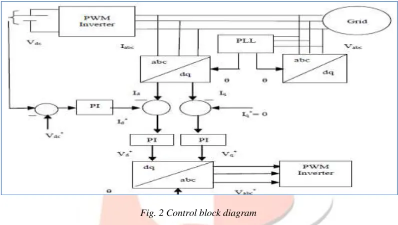
Fig. 2 Control block diagram
In this control method the inverter output current and grid voltage are taking as reference into the abc to dq block, this abc to dq block known as a Park transformation. This Park Transformation is converted three phase reference frame into two phase rotating frame. The two phase current component is Id, First Id taking a zero as reference and second Id is taking a Vdc as reference, then it’s two components are taken into the PI controller. PI controller is use into the PLL as a error tuning. Then it will be connected with the Dq to abc block. This block known as an inverse Park Transformation. It is converted two phase rotating frame into the three phase reference frame and it will supply to the PWM inverter.[2]
A. PLL
The words PLL means “Phase- Locked Loop”, PLL is a control system that generates an output signal whose phase is related
to the phase of an input signal. While there are several differing types, it is easy to initially visualize as an electronic
circuit consisting of a variable frequency oscillator and a phase detector. The oscillator generates a periodic signal, and the phase detector compares the phase of that signal with the phase of the input periodic signal, adjusting the oscillator to keep the phases
matched. Bringing the output signal back toward the input signal for comparison is called a feedback loop since the output is "fed
IJEDR1702163
International Journal of Engineering Development and Research (www.ijedr.org)971
Fig. 3 PLLA PLL is a feedback system that includes a VCO, phase detector, and low pass filter within its loop. Its purpose is to force the VCO to replicate and track the frequency and phase at the input when in lock. The PLL is a control system allowing one oscillator to track with another. It is possible to have a phase offset between input and output, but when locked, the frequencies must exactly track.[5]
B. Benefits of PLL
Eliminates the problem of frequency drift.
Increase battery life of product
Less manufacturing cost
PLL System are very important in generating accurate and stable frequency.
III.SIMULATION AND RESULTS
A. Simulink model
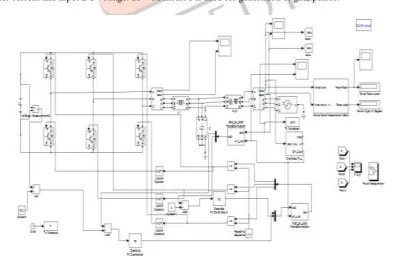
Fig.4 shows the Simulink model of grid connected inverter control using PLL. Constant DC voltage is given as an input. In three phase voltage source inverter, 6 IGBTs are used. L-C filter is used to reduce harmonics. Interfacing reactor is used and inverter currents are fed to the grid as shown in Simulink model.
In control method PLL is used to track the desired frequency, Park and clarke transformations are done in order to individually control the inverter current and input DC voltage. SPWM method is used for generation of gate pulses.
IJEDR1702163
International Journal of Engineering Development and Research (www.ijedr.org)972
B. Waveforms and results for constant DC and balanced grid frequencyI. Parameters
• Vdc=676V; • Vac=230v; • f=50Hz • R=0.4ohm; • C=0.01 microF; • L1=200 mH • L2=0.1mH; II. Waveforms
Fig.5 Inverter output current and grid voltages
III. Results:
Fig.6 THD analysis
IJEDR1702163
International Journal of Engineering Development and Research (www.ijedr.org)973
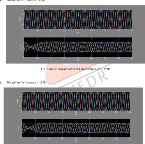
C. Waveforms and results for unbalanced grid frequencyI. Parameters
• Vdc=676V; • Vac=230v;
• f1=50Hz at time 0 to 0.2 sec. • f2=48/52Hz at time 0.2 to 0.3 sec. • R=0.4ohm;
• C=0.01 microF; • L1=200 mH • L2=0.1mH;
II. Waveforms for frequency= 48 Hz
Fig. 7 Inverter output current and grid voltages for f=48 Hz
III. Waveforms for frequency= 52 Hz
IJEDR1702163
International Journal of Engineering Development and Research (www.ijedr.org)974
IV. ResultsIn case of unbalance grid frequency, this control system gives near to unity power factor operation, as inverter output currents are in phase with grid voltages as shown in waveforms.
IV.CONCLUSION
This control method based on PLL gives THD less than 5% and power factor is unity. Also in case of grid frequency Unbalance, SPWM control with PLL method gives power factor near to unity.
ACKNOWLEDGEMENT
The authors sincerely thank to Electrical Engineering Department, Chhotubhai Gopalbhai Patel institute of technology, Bardoli.
REFERENCES
[1] Y. Xue and L. Chang,”Close-Loop SPWM Control for Grid-Connected Buck-Boost Inverters”, 35th Annual IEEE Power Electronics Specialists Conference, pp. 3366-3371, Germany-2004.
[2] A. Abobakr and A. Zekry. “Three phase grid connected inverter”, PhD thesis. Cairo, Egypt: Ain-Shams University, 2008. [3] Qingrong Zeng and Liuchen Chang. “Study of Advanced Current Control Strategies forThree-Phase Grid-Connected
PWM Inverters for Distributed Generation.” Toronto, Canada : IEEE Conference on Control Applications, 2005
[4] Ahmed Abdalrahman ,AbdalhalimZekry and Ahmed Alshazly , ” Simulation and Implementation of Grid-connected Inverters”, International Journal of Computer Applications , Volume-60, December 2012 ISSN: 41-49.
[5] K. De Brabandere and T. Loix,”Design and Operation of a Phase-Locked Loop with Kalman Estimator-Based Filter for Single-Phase Applications”, IEEE Conference, pp. 525-530, Belgium-2006.