Article
Experimental Study on the Heat Transfer
Characteristics of the Enhanced Fin-Tube Heat
Exchanger Applied a Coiled Turbulator
Sun-Joon Byun 1, Sang-Jae Lee 2, Jae-Min Cha 2, Zhen-Huan Wang 2 and Young-Chul Kwon 3,*
1 Thermal & Fluid System Group, Korea Institute of Industrial Technology, 89 Yangdaegiro-gil, lpjang-myeon, Seobuk-gu, Cheonan-si, Chungcheongnam-do 31056, Korea; bjky21@korea.ac (S.-J.B.)
2 Department of Mechanical Engineering, Sunmoon University,70 sunmoon-ro 221 beon-gil, Tangjeong-myeon, Asan-si, Chungcheongnam-do 31460, Korea; heattube@sunmoon.ac.kr (S.-J.L.);
jaemin-cha@naver.com (J.-M.C.); huan_2014@nate.com (Z.-H.W.)
3 Division of School of Mechanical and ICT Covergence Engineering, Sunmoon University, 70 sunmoon-ro 221 beon-gil, Tangjeong-myeon, Asan-si, Chungcheongnam-do 31460, Korea;
yckweon1@sunmoon.ac.kr (Y.-C.K.)
* Correspondence: yckweon1@sunmoon.ac.kr; Tel.: +82-41-530-2396
Abstract: This study presents the comparison of heat transfer capacity and pressure drop characteristics between a basic fin-tube heat exchanger and a modified heat exchanger with the structural change of branch tubes and coiled turbulators. All experiments were carried out using an air-enthalpy type calorimeter based on the method described in ASHRAE standards, under the heat exchanger experimental conditions. 14 different kinds of heat exchangers were used for the experiment. Cooling and heating capacities of the turbulator heat exchanger were excellent, compared to the basic one. As the insertion ratio of the coiled turbulator and the number of row increased, the heat transfer performance increased. However, the capacity per unit area was more effective in 4 rows than 6 rows, and the cooling performance of the 6 row turbulator heat exchanger (100% turbulator insertion ratio) was down to about 6% than that of 4 row one. As the water flow rate and the turbulator insertion ratio increased, the pressure drop of the water side increased. This trend was more pronounced in 6 rows. In the cooling condition, the pressure drop on the air side was slightly increased due to the generation of condensed water, but was insignificant under the heating condition. The power consumption of the pump was more affected by the water flow rate than the coiled turbulator. The equivalent hydraulic diameter of a tube by the turbulator was reduced and then the heat transfer performance was improved. Thus, the tube diameter was smaller, the heat flux was better.
Keywords: capacity; cooling and heating; fin-tube heat exchanger; pressure drop; turbulator
1. Introduction
In the present era, the demand for a pleasant living condition has increased with the advancements in technology. This demand leads to a drastic rise in energy usage, which also brings about an issue of energy resource depletion and environmental damages. These critical issues are currently being addressed through a varying array of approaches. As energy usage increases for both personal and industrial purposes, efforts are being made to increase the energy consumption efficiency in the field of heating, ventilating, and air conditioning (HVAC) systems to minimize its effects on the environment.
The miniaturization of electronic communication and other mechanical devices leads to issues, such as increased heat release rate per unit area and further spatial limitations. Accordingly, various studies on reducing weight and enhancing the heat exchanger performance are being performed to address such issues [1,2]. The heat transfer performance and efficiency can be enhanced by improving the tube and fin structure and further developing the related optimal design principles of the heat exchanger. Fin-tube heat exchangers are often used in industrial boilers, vehicle radiators, and HVAC and cooling systems. Hence, vigorous researches are being conducted to increase the heat exchanger performance.
The heat transfer process in a fin-tube heat exchanger comprises the heat transfer of latent and sensible heat. With the latent heat process, the state of the working fluid changes and the sensible and latent heats coexist. Meanwhile, with the sensible heat process, the state of the working fluid does not change. Considering these processes, the fin-tube heat exchanger form must be redesigned. In a basic fin-tube heat exchanger, many long tube circuits are connected to a multi-branch. Complex branch tubes are often used depending on the use case of the heat exchanger. The heat transfer efficiency is heavily affected by the latent heat transfer performance. Thus, various tube circuits must be implemented along with the tube and the branch tube circuit design for the maximum latent heat transfer performance. However, with the heat exchangers that use the sensible heat process, the tube circuit must be kept short and simple to optimize the performance of the heat exchanger.
2. Experimental setups and procedure
2.1. Subsection
In this research, standard branch tubes in a basic fin-tube heat exchanger were changed to vertical straight and U-bend ubes. Furthermore, the heat transfer performance of the modified turbulator heat exchanger with a coiled turbulator implemented had been explored. To compare the turbulator heat exchanger with a basic fin-tube heat exchanger, a psychrometric calorimeter (air-enthalpy type) and a constant temperature water bath were used. Figure 1 depicts the psychrometric calorimeter and the schematics of the experimental setup.
Figure 1. Schematics of the psychrometric calorimeter.
Psychrometric calorimeter is composed of a suction type chamber, constant temperature water bath, air sampling unit, and a data acquisition system. All components other than the constant temperature water bath is situated in the constant temperature and constant humidity chamber. The air flow to the heat exchanger that is installed on the immediate inlet of the constant temperature and humidity chamber is controlled by a HVAC system. The HVAC system, which is set up in the chamber, provides fine control over the inlet air condition (temperature, humidity). The dry/wet temperature of the chamber inlet/outlet is measured by the air sampling unit. The flow rate on the air side is controlled by the suction fan and the subsequent motor controller that resides on the rear end of the chamber. The pressure drop of the air side is measured by the differential pressure nozzle in the chamber. The temperature of the water that flows to the tube in the heat exchanger is controlled and monitored by the chiller and heater PID control within the constant temperature water bath. The dry/wet temperature of the chamber inlet/outlet is measured by the air sampling unit. The flow rate on the air side is controlled by the suction fan and the subsequent motor controller that resides on the rear end of the chamber. The pressure drop of the air side is measured by the differential pressure of nozzle in the chamber. The temperature of the water that flows to the tube in the heat exchanger is controlled and monitored by the chiller and heater PID control within the constant temperature water bath. The error range of the temperature is known to be ±0.3℃. The flow rate of the water inflow is controlled by varying the rpm of the pump. The inlet/outlet temperature and pressure of the heat exchanger is measured by installing a RTD and a pressure transmitter, and the flow rate is measured by a turbine flow meter (measurement precision of <0.5%). The psychometric calorimeter is designed within the international standards stated in the ASHRAE [16] and the capacity of the air side remains within ±1.0% deviation at steady state. The reproducibility is within ±0.5%.
heat exchanger performance. Once the air temperature, the air flow rate, the water inlet temperature and the water flow rate reaches stead state, the temperature difference of the water inlet /outlet is monitored until it stabilizes within ±0.2℃. Then, the flow rate, dry/wet temperature, and pressure difference for air, and the flow rate, the inlet/outlet temperatures of water are measured. Detailed specifications are shown in Table 1. Regarding the experimental conditions of the heat exchanger, the temperature conditions on the air side is controlled by KS C 9306 [17] while the water side uses KS B 6377 [18] to control the temperature condition (cooling and heating).
Figure 2 depicts the schematics of the constant temperature bath and the experimental setup. The constant temperature bath installed on the outside of the constant temperature and constant humidity chamber uses the water as the operated fluid to measure the performance of the heat exchanger. The inlet temperature on the water side is controlled using a PID, which provides accuracy within the range of ±0.3℃. A 6.0 HP pump is also implemented that allows the maximum water flow rate to be up 50 LPM .
Figure 2. Schematics of the constant temperature bath.
(a) (b)
Figure 3. Schematics of the basic and the turbulator heat exchangers. (a) Basic heat exchanger and tube structure; (b) Coiled turbulator heat exchanger and tube structure.
Figure 3 shows the internal structures of the basic heat exchanger and the turbulator heat exchanger used for the experiment. The turbulator heat exchanger shows similar structure with the exception of the vertical straight tube of the head and the 2 row branch tube structure at the rear end. Also, the heat exchanger performance depending on the existence of a coiled turbulator, which magnifies the turbulence effect of the fluid flow within the tube, is compared. To compare the
T P
capacity depending on the insertion ratio of the coiled turbulator, experiments are carried out at 0, 25, 50 and 100% insertion ratios.
In total, 14 different kinds of heat exchangers were used for the experiment, and the details of the basic heat exchanger and the turbulator heat exchanger are listed in Table 2. Furthermore, the heat exchanger performance depending on the existence of a coiled turbulator, which magnifies the turbulence effect of the fluid flow within the tube, were compared.
Table 1. Heat exchanger experimental conditions.
Item
Air side (KS C 9306) Water side (KS B 6377)
Temperature (℃) Flow rate (m3/min)
Inlet temperature(℃)
Flow rate (kg/min)
Cooling condition
27.0 ± 0.3 (dry bulb) 19.5 ± 0.2 (wet bulb)
20
7.0 ± 0.2 5, 10, 15, 20 Heating
condition
18.0 ± 0.3 (dry bulb)
13.0 ± 0.2 (wet bulb) 60.0 ± 0.2 5, 10, 15, 20
Table 2. Specifications of the basic and the turbulator heat exchangers.
Item Dimensions Front
Area (m2)
Fin pitch (mm) Fin type Number of rows Tube diameter (mm) Tube thichness (mm) Insertion ratio (%)
Basic 380(L) x 420(H) x 330(D)
0.16 8 Slit 4, 6
12.7 0.3 -
Turbulator 15.9 0.4 0, 25,
50, 100
Figure 4 shows the shape of the coiled turbulator (4 rows, 6 rows) applied in this experiment. The thickness (t) and the pitch (p) of the coil are 1.2 and 8.0 mm. And the diameter (d) of the insert coil is 12.1 and 15.1 mm. Figure 5 depicts the turbulator heat exchanger section of 4 rows and 6 rows depending on the coiled turbulator insertion ratio. With the 0% coiled turbulator insertion ratio of heat exchanger, only the branch tube shape was changed from the fin-tube heat exchanger. Lastly, depending on the insertion ratio of the coiled turbulator within the tube, the coiled turbulator type were categorized into 0, 25, 50 and 100%.
Insertion ratio of the coiled turbulator
0% 25% 50% 100%
(a)
(b)
Figure 5. Schematics of heat exchanger section for the coiled turbulator insertion ratio. (a) 4 rows; (b) 6 rows.
2.2. Experimental method
The cooling and heating capacity of the heat exchanger is calculated through the method suggested in KS C 9306 and KS B 6377, which uses the measured air temperature of the inlet and the flow rate and temperature of the outlet. All data signals are collected and transformed using the DAQ system. The DAQ system then converts the signal using GPIB, and sends it to the computer. Once the temperature and flow rate of air and the inlet temperature and air flow rate of water comes to a steady state, and the temperature fluctuation is less than ±0.2℃. Data such as air flow rate, inlet/outlet dry and wet temperature, pressure difference of air, water flow rate and inlet/outlet temperature is collected in 3 second intervals for 30 minutes. Further calculations are made using arithmetic mean method.
For accurate comparison of the basic fin-tube heat exchanger and the fin-tube heat exchanger with modified tube structure and added turbulator, the specifications of the fins and tubes for all heat exchangers were set to be exactly the same. To address the reliability for the experimental results, the error for the heat balance for air and water side is set to maximum error range of ±4.0%. Furthermore, a wattmeter was used to measure the consumption power of the pump due to the water flow rate of both the basic fin-tube heat exchanger and the turbulator heat exchanger.
2.3. Data reduction
The inlet/outlet temperature and the flow rate measured for the air side and the water side were used to obtain the capacity of the air side and the water side using equations (1) and (2). The mean capacity was calculated from the arithmetic average of the capacity of the air side and the water side. The measured values and the fluid properties were used to calculate the capacity of the heat exchanger.
= , − , (1)
The inlet/outlet of the water side passes through the air side and the heat exchanger tube, which passes through the front area of the heat exchanger. The pressure difference was determined by measuring the inlet/outlet pressure of the water side. Equations (3) and (4) were used to calculate the value.
∆ = , − , (3)
∆ = , − , (4)
To secure the reliability for this experiment, the following heat balance was used for the measured capacity of the air and the water side.
% = − × 100 (5)
In this section, Q, m, h, C, and T represents the capacity, mass flow rate, enthalpy, specific heat and temperature, respectively. The subscripts a, w, i, o and p indicates air, water, inlet, outlet and static pressure.
3. Results and Discussion
Figure 6 shows cooling capacities on 4 row and 6 row basic and coiled turbulator heat exchangers according to the change in water flow rates. In the case of the 4 row heat exchanger, cooling capacities of the basic heat exchanger were about 2,193 to 4,772 W and those of the coiled turbulator heat exchanger with 0% turbulator insertion ratio were about 2,334 to 5,077 W, at water flow rates of 5 to 20 kg/min. On the other hand, cooling capacities of the turbulator heat exchanger (0, 25, 50 and 100% turbulator insertion ratio) were improved by about 6.4, 13.5, 24.8 and 41.0%, respectively, compared with the basic heat exchanger, at the water flow rate of 20 kg/min. At the same water flow rate, the cooling capacity of the turbulator heat exchanger is improved more than that of the basic heat exchanger because of the arrangement structure of branch tubes and the turbulence effect due to the coiled turbulator inserted in tubes.
Figure 6. Cooling capacities on the heat exchanger for water flow rate.
basic heat exchanger and the turbulator heat exchanger, those of the turbulator heat exchanger (0, 25, 50 and 100% turbulator insertion ratio) were improved by about 6.7, 13.5, 26.9 and 44.9%, compared with the basic heat exchanger, at the water flow rate of 20 kg/min. Comparing these results with the cooling capacity of the turbulator heat exchanger, cooling capacity of the 6 row turbulator heat exchanger is about 40.8% higher than that of the 4 row heat exchanger. And as the insertion rate of the coiled turbulator increases, the improvement of the cooling capacity is larger. This is due to the heat transfer augmentation by the turbulent flow caused by the coiled turbulator inserted in tubes and the increase in the heat transfer effect by the sensible heat and latent heat between the inflow moist air and the heat exchanger.
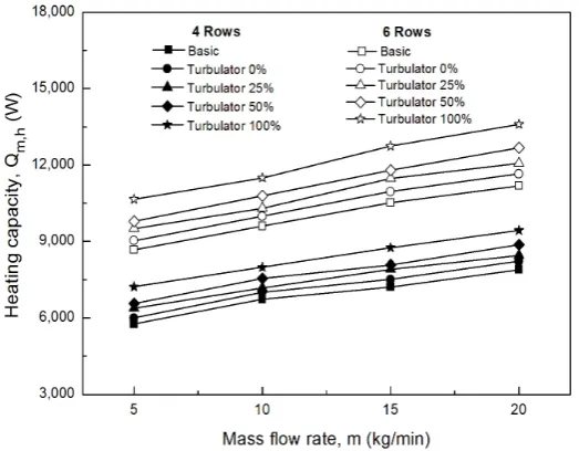
Figure 7 shows heating capacities of 4 row and 6 row basic heat exchangers and turbulator heat exchangers according to water flow rates. Heating capacities of the 4 types of the turbulator heat exchanger (0, 25, 50 and 100% turbulator insertion ratio) were compared with those of the basic heat exchanger in water flow rates of 5 to 20 kg/min. As the water flow rate increased, the heating capacity was improved. Heating capacities of the 4 row basic heat exchanger were about 5,751 to 7,891 W and those of the 4 row turbulator heat exchanger with 0% turbulator insertion ratio were about 5,990 to 8,220 W, at water flow rates of 5 to 20 kg/min. Also, the heating capacity of the 6 row basic heat exchanger were about 8,663 to 11,183 W and those of the 6 row turbulator heat exchanger (0% turbulator insertion ratio) were about 9,024 to 11,649 W, at the same water flow rate. Based on the 4 row basic heat exchanger, at the water flow rate of 20 kg/min, the heating capacity of the 6 row basic heat exchanger increased by about 41.7%. Those of 4 row and 6 row turbulator heat exchangers (0% turbulator insertion ratio) were improved by about 4.2 and 47.6%, respectively. At the same water flow rate (20 kg/min), the heating capacity improvement of the turbulator heat exchanger (50% turbulator insertion ratio) increased by about 12.5% at the 4 row basic heat exchanger and by about 60.6% at the 6 row one. This means that the heat transfer performance of the heat exchanger is improved applying the coiled turbulator to the basic heat exchanger. As can be seen from the experimental conditions, the heating capacity is greater than the cooling capacity (Figure 6). This is because the difference in temperature between water and the inflow air is greater than about 20℃
under the heating condition. That is, the larger the temperature difference between two fluids is, the better the heat exchange ability is.
Figure 7. Heating capacities on the heat exchanger for water flow rate.
(a)
(b)
Figure 8. Pressure drops of the water side and consumption powers for water flow rate. (a) 4 rows; (b) 6 rows.
Figure 9 shows pressure drops of the air side on the basic and turbulator heat exchangers under cooling conditions. Pressure drops of the air side on 4 row basic and turbulator heat exchangers were about 0.06 to 0.08 kPa but the fluctuation width on the water flow rate change did not appear much. However, pressure drops of the air side on the turbulator heat exchanger were larger than that of the basic one. At the same water flow rate, the pressure drop increased as the insertion rate of the coiled turbulator increased. Under cooling conditions, condensed water can easily be generated on the surface of the fin-tube heat exchanger. If the convective heat transfer performance in the tube is increased by the coiled turbulator inserted in tubes, the amount of condensed water generated on the surface of the fin-tube heat exchanger is increased, and as a result, the inflow moist air flowing through the heat exchanger is disturbed and the fluid flow around the tube bundle is changed. Pressure drops of the 6 row heat exchanger showed a similar tendency to those of the 4 row heat exchanger, at water flow rates of 5 to 20 kg/min. At the turbulator insertion rates of 0, 25, 50 and 100%, pressure drops of the air side were increased to about 0.1 to 0.15 kPa and were slightly larger than those of the 4 row heat exchanger. This is because the heat exchanger area of the air side on the 6 row heat exchanger is increased by about 50% than that of the 4 row heat exchanger, and the latent heat region at the tube bundle within the heat exchanger is relatively increased. Therefore, condensed water influencing the air flow within the heat exchanger was generated more than the 4 row heat exchanger. Also, as the insertion ratio of the coiled turbulator in tubes increased, the pressure drop of the air side increased somewhat. And condensed water of 4 row and 6 row turbulator heat exchangers increased to about 34 and 42% respectively, compared with the basic heat exchanger. That is, the increase in the amount of condensed water under the cooling condition indicates that the heat transfer performance due to the increase in the latent heat effect is improved.
Figure 9. Pressure drops of the air side for water flow rate under the cooling condition.
exchanger compared to the 4 row heat exchanger is considered to be due to the pressure loss by the flow friction induced by the increase of the heat transfer area of the air side.
Figure 10. Pressure drops of the air side for water flow rate under the heating condition.
Figure 11 shows cooling heat fluxes (heat transfer rate per unit area) and consumption powers of the pump for outer diameters of 12.7 and 15.9 mm. Figure 11(a) shows that cooling heat fluxes of the 4 row basic heat exchanger and the turbulator heat exchanger (100% turbulator insertion ratio) with outer diameters of 12.7 and 15.9 mm are about 322.2, 454.5, 284.2 and 400.8 kW/m2, respectively,
at the water flow rate of 20 kg/min. As the tube diameter decreases, the heat flux is improved. Therefore, when the coiled turbulator is inserted into the tube, the equivalent hydraulic diameter of the heat exchanger is reduced, thereby improving the heat transfer performance. In addition, the heat transfer performance of the turbulator type with the coil inserts than the basic type is more effective due to the enhancement of convective heat transfer by the turbulent generation effect in the tube. The consumption powers of the pump increased as the water flow rate increased, but the change in the tube diameter and the influence on the insertion of the coiled turbulator were insignificant.
Figure 11(b) shows that cooling heat fluxes of the 6 row basic heat exchanger and the turbulator heat exchanger (100% turbulator insertion ratio) with outer diameters of 12.7 and 15.9 mm are about 294.3, 426.7, 261.0 and 378.3 kW/m2, respectively, at the water flow rate of 20 kg/min. Since the heat
transfer area of the air side on the 6 row heat exchanger is larger than the 4 row one, the cooling heat flux of the 6 row one is higher than that of the 4 row one. Based on the 4 row basic heat exchanger at the water flow rate of 20 kg/min, the cooling heat flux of the turbulator heat exchanger (100% tubulator insertion ratio) increased by about 41.0% at the diameter of 12.7 mm and increased by about 24.3% at the diameter of 15.9 mm. In case of the 6 row heat exchanger, the cooling heat flux on the turbulator heat exchanger (100% turbulator insertion ratio) increased by about 44.9% at the diameter of 12.7 mm and increased by about 28.5% at the diameter of 15.9 mm.
heat transfer, and it is considered that the increase width of the heat transfer will gradually decrease even if the water flow rate is increased.
(a)
(b)
Figure 11. Cooling heat fluxes and consumption powers for outer diameter. (a) 4 rows; (b) 6 rows.
Figure 12 shows heating heat fluxes and power consumptions of the pump for the outer diameters of 12.7 and 15.9 mm. Figure 12(a) shows that heating heat fluxes of the 4 row basic heat exchanger and the turbulator heat exchanger (100% turbulator insertion ratio) with outer diameters of 12.7 and 15.9 mm are about 532.8, 636.8, 469.9 and 561.6 kW/m2, respectively, at the water flow rate
Figure 12(b) shows heating heat fluxes of the 6 row basic heat exchanger and the turbulator heat exchanger (100% turbulator insertion ratio) with outer diameters of 12.7 and 15.9 mm are about 503.3, 612.1, 446.3 and 542.7 kW/m2, respectively, at the water flow rate of 20 kg/min. The heat transfer area
of the air side on the 6 row heat exchanger is larger than that of the 4 row one. Therefore, the total capacity is large, but the heat flux can be varied. The capacity of the 6 row heat exchanger is excellent in 12.7 mm outer diameter, but the 4 row heat exchanger is more excellent in 15.9 mm outer diameter. This is because the heat transfer efficiency is continuously improved with increase in heat transfer area when the heat exchanger is changed from 4 row to 6 row in the case of 12.7 mm outer diameter. On the other hand, in the case of 15.9 mm outer diameter, the total capacity increases due to the increase of the heat transfer area, but the heat flux decreases. And then the heat transfer efficiency becomes lower than the area increase ratio on the capacity. That is, the heat flux according to the change in the outer diameter is larger in 6 row than in 4 row, and that decreases as the outer diameter
(a)
(b)
is larger. Based on the 4 row basic heat exchanger at the water flow rate of 20 kg/min, the heating heat flux of the turbulator heat exchanger (100% turbulator insertion ratio) increased by about 19.5% at the outer diameter of 12.7 mm and decreased by about 5.4% at the outer diameter of 15.9 mm. In case of the 6 row heat exchanger, the heating heat flux increased by about 21.6% at the outer diameter of 12.7 mm and decreased by about 7.8% at the outer diameter of 15.9 mm. In results of the heating experiment, the heating heat flux increased almost linearly, but the tendency to slow down the increase in heat flux shown in the cooling experiment above water flow rate of about 15.0 kg/min was insignificant.
Figure 13 shows pressure drops of the water side for the outer diameter (12.7 and 15.9 mm) under heating conditions. When the water flow rate is 20 kg/min, pressure drops of the basic heat exchanger are about 2.8 and 1.98 kPa when those of the turbulator heat exchanger (100% turbulator insertion ratio) are about 4.7 and 3.2 kPa, respectively. Under the same water flow rate, the pressure
Figure 13. Pressure drops of the water side for the outer diameter under the heating condition.
drop increases by the turbulator inserts in tubes, and that decreases when the tube outer diameter is large. From the pressure drop experiments in 4 and 6 rows, the pressure drop increases as the tube outer diameter decreases and the water flow rate increases. And the pressure drop increases linearly with the increase of the water flow rate when the turbulator insertion ratio is 100%. This is because the pressure loss increases due to the increase of the turbulator insertion rate and the flow rate.
Figure 14 shows pressure drops of the air side for the outer diameter (12.7 and 15.9 mm) under cooling conditions. When the water flow rate was 20 kg/min, pressure drops of the 4 row basic heat exchanger were about 0.07 and 0.063 kPa when those of the turbulator heat exchanger (100% turbulator insertion ratio) were 0.08 and 0.065kPa, respectively. The changes in the outer diameter and the water flow rate was slightly different, but the pressure drop of air side mass very low compared to the pressure drop of the water side. In the 6 row exchanger, the pressure drop increased as the water flow rate increases. However, the pressure drop due to the variation of the outer diameter and the application of the turbulator was somewhat larger than those of the 4 row heat exchanger.
At the water flow rate of 20 kg/min, pressure drops of the basic heat exchanger were about 0.13 and 0.11 kPa when those of the turbulator heat exchanger (100% turbulator insertion ratio) were about 0.15 and 0.12 kPa, respectively. The 6 row heat exchanger has a larger heat transfer area than the 4 row heat exchanger, which facilitates condensate generation on the heat exchanger and the tube surface under cooling conditions. It narrows the flow path on the air side of the heat exchanger and interrupts the air flow. As a result, the pressure drop becomes large.
5. Conclusions
This paper describes the comparison of heat transfer capacity and pressure drop characteristics between the basic fin-tube heat exchanger and the modified heat exchanger with the structural change of branch tubes and coiled turbulators. The complicated zig-zag branch tubes were not applied and the coiled turbulators inside tubes were inserted. All experiments were carried out using the air-enthalpy type calorimeter. The total 14 experiments were performed for the heat exchanger type (basic, coiled turbulator), the row (4 and 6 rows), the diameter (12.7 and 15.9 mm), the turbulator insertion ratio (0, 25, 50 and 100%), the water flow rate (5, 10, 15 and 20 kg/min) and the experimental condition (heating, cooling). The cooling and heating capacity of the heat exchanger is calculated through the method suggested in KS C 9306 and KS B 6377. From the present experimental work, the following conclusions are summarized as follows:
(1) Cooling and heating capacities of the turbulator heat exchanger (0, 25, 50 and 100% turbulator insertion ratio) were improved by about 6.4 to 41.0% and about 6.7 to 44.9% for 4 rows, about 4.2 to 19.5% and about 4.2 to 21.6% for 6 rows, compared with the basic heat exchanger. The cooling and heating capacity of the 6 row turbulator heat exchanger were about 40.8% and about 44.2% higher than those of the 4 row one at 100% turbulator insertion ratio. As the insertion ratio of the coiled turbulator and the number of row increased, the heat transfer performance increased.
(2) As the water flow rate and the turbulator insertion ratio increased, the water pressure drop increased. Pressure drops of the turbulator heat exchanger (0, 25, 50, 100% turbulator insertion ratio) increased by about 14.3 to 67.9% for 4 rows, about 23.8 to 59.5% for 6 rows, compared with the basic heat exchanger. Pressure drop of the turbulator heat exchanger of the 6 rows were about 42.6% higher than those of the 4 rows at 100% turbulator insertion ratio. Also, in the cooling condition, the pressure drop on the air side was slightly increased due to the generation of condensed water, but was insignificant under the heating condition. The power consumption was more affected by the water flow rate than the coiled turbulator.
were down to about 3.9% (for 12.7 mm) and about 3.4% (for 15.9 mm) than those of 4 rows. Also, the pressure drop increases by the turbulator inserts in tubes, and that decreases when the tube outer diameter is large. The tube equivalent hydraulic diameter by coiled turbulators was reduced and then the heat transfer performance was improved.
Acknowledgments: This work was supported by the Sun Moon University Research Grant of 2015.
Nomenclature
Cp specific heat (J/kg·K)
h convective heat transfer coefficient (W/m2·K) m mass flow rate (kg/min)
P pressure (kPa
)
△P pressure drop (kPa
)
q heat flux (W/m2
)
Q capacity (W)T temperature (℃
)
Subscripts
a air
c cooling
h heating
i inlet
o outlet
m mean
w water
References
1. Wang, C.C.; Tao, W.H.; Chang, C.J. An investigation of the air side performance of the slit fin-and-tube heat exchangers, Int. J. Refrig. 1999, 22, 595–603.
2. Du, Y.J.; Wang, C.C. An experimental study of the air-side performance of the super slit fin-and-tube heat exchangers, Int. J. Heat Mass Transf. 2000, 43, 4475–4482.
3. Wang, C.C.; Lee, W.S.; Sheu, W.J. A comparative study of compact enhanced fin-and-tube heat exchangers,
Int. J. Heat Mass Transf. 2001, 44, 3565–3573.
4. Dejong, N.C.; Jacobi, A.M. An experimental study of flow and heat transfer in parallel-plate arrays: local, row-by-row and surface average behavior, Int. J. Heat Mass Transf. 1997, 40, 1365–1378.
5. Lee, J.D.; Yun, J.Y. Research review for parametric characteristics on heat exchanger, Trans. Korean Soc. Mech. Eng. 1993, 33, 1, 936–941.
6. Yun, J.W.; Yun, J.Y.; Kim, M. Numerical study on the characteristics of flow an heat transfer in finned tube heat exchanger, Trans. Soc. Air-Con. Refrig. Eng. 1996, 25(2), 137–150.
7. Kang, H.C. Fin efficiency of the heat exchanger, Trans. Soc. Air-Con. Refrig. Eng.1999, 1151–1121.
8. Lee, M.K.; Chang, K.S.; Kweon, Y.C.; Yun, J.W. Development on new fin of fin-tube heat exchanger for A/C system, Proc. Soc. Air-Con. Refrig. Eng. 2002, 153–158.
9. Lee, J.H.; Lim, M.K; Kang, H.C. Forced convection characteristics of V type circular-finned tube heat exchanger, Proc. Soc. Air-Con. Refrig. Eng.2009, 1348–1354.
10. Kim, N.H.; Youn, B.; Webb, R.L. Heat transfer and friction correlations for plain fin and tube heat exchangers, Proc. 11th Int. Heat Transf. Conf. 1998, 6, 209–213.
12. Chang, H.S.; Chun, Y.W.; Chung, I.K. Study on performance of plate fin-oval tube heat exchanger with vortex generators, Proc. Korean Soc. Mech. Eng. 2005, 345–350.
13. Jin, D.H.; Na, B.; Jang, D.Y.; Yun, J.Y. Study on the heat transfer and pressure drop characteristics in the plain fin heat exchangers with round tube, Proc. Soc. Air-Con. Refrig. Eng. 1999, 306–309.
14. Kurtbaş, İ.; Durmus, A.; Eren, H.; Turgut, E. Effect of propeller type swirl generators on the entropy generation and efficiency of heat exchangers, Int. J. Thermal Sciences 2007, 46, 300–307.
15. Yakut, K.; Sahin, B. The effects of vortex characteristics on performance of coiled wire turbulators used for heat transfer augmentation, Appl. Eng. 2004, 24, 2427–2438.
16. ASHRAE Standard, Methods of testing forced circulation air cooling and air heating coils, 1978, 33-78. 17. Korean Standard Association, KS Air conditioner: KS C 9306, 2007.
18. Korean Standard Association, KS Fan coil units: KS B 6377, 2009.