Variable Laser Wall-plug Efficiency
Shamanta Hoque Shammi, Columbia University
Abstract— in most studies reported in literature, a flat, constant coefficient is used to convert the amount of optical power required at the input of an optical link into the effective power consumption. This constant coefficient approach is very simple to apply but not accurate, since laser efficiencies are dependent on the optical output power in addition to the operating temperature. In this paper the relationship between laser wall plug efficiency and optical power output is investigated and the effect of this variance on optical links and on-chip laser source electric power consumption is presented.
I. INTRODUCTION
It is often important to quantitatively asses the quality, performance and characteristics of laser sources. This is often done through evaluating certain significant parameters from which it can be determined how well a laser source is performing. One of the most significant parameter of an electrically pumped laser, is the Laser Wall-plug Efficiency, which is the measure of how efficiently a laser source is converting electrical power into optical power. Even though, often a constant value of wall-plug efficiency is associated with a laser, in reality it varies significantly with the optical power output. The laser wall-plug efficiency also has high variance with change in temperature. Therefore, it is crucial to understand and take this variance into consideration for optimal laser performance.
II.LASER SOURCE
The manner in which a Laser’s wall-plug efficiency varies with optical power output and with temperature, depends significantly on the laser source structure and its operating principles. For the purpose of this project two kind of semiconductor laser sources are used to derive these relationships.
A. Diode Laser
A diode laser (fig.1.a) consists of a p-n diode with an active region where electrons and holes recombine resulting in light emission. It contains an optical cavity where stimulated emission takes place. The laser cavity consists of a waveguide terminated on each end by a mirror. Photons, which are emitted into the waveguide, can travel back and forth in this waveguide provided they are reflected at the mirrors. The distance between the two mirrors is the cavity length (L) [4]. B. Vertical Cavity Surface Emitting Laser
A vertical cavity surface emitting laser (VCSEL) (fig.2.b) is a specialized laser diode that has promising application in fiber optic communications by improving efficiency and increasing data speed. It can be monolithically integrated and, unlike edge emitting laser diode, the VCSEL emits its coherent energy perpendicular to the boundaries between the layers.
The inner cavity containing the amplifying layers is surrounded by electrically conductive layer stacks that form the laser mirrors which provide optical feedback. VCSELs designed for emission wavelengths in the 850 to 980 nm spectral range require about 8 µm of epitaxial grown material, whereas the active region is composed of just a few quantum wells (QWs) with some ten nm thickness. The pin-type doping configuration is similar to conventional edge-emitting lasers (EELs). In the most simple device layouts, electric current is injected from ohmic contacts on the top epitaxial side and the backside of the substrate [5], [6]. Even though currently some of 980, 850 and 780 nm devices are commercialized into light wave systems, aiming exploring applications, 1300-1550 nm y Usually have small diverging angle, low threshold current and single laser mode output. The structure can be easily
integrated in two-dimensional array configuration [4]. All these advantages make VCSEL an ideal candidate for integrated photonics Network on chip (NoC). Therefore, it is important to study the true wall-plug efficiency of VCSEL.
Fig.1- (a) Schematic representation of an index guided Diode Laser and its diverging output beam profile [4]. (b) Schematic representation and operation of a VCSEL [5].
Output optical power (mW)
Fig.2- Wall plug efficiency of different models of VCSEL for certain optical power output.
(b) (a)
12 10
8 4
2 0
850 nm VCSELwith 3x3 gm2 oxide
aperture 963 nm
Lithigraphic oxide-free VCSEL(4µm diameter)
6
VCSEL array with… ALGaAs/GaAs
VCSEL
15.00% 10.00% 5.00% 0.00%
AIGalnP-based 650 nm VCSEL 975-nm VCSEL
20.00%
Oxide- confined 850- nm VCSEL (3.5 μm oxide aperature)
25.00%
Oxide confined 850nm VCSEL array
VCSEL Output Power vs. Wall-plug Efficiency for different Models and different material used. 1550 nm InP-
based VCSEL
40.00% 35.00% 30.00%
2
∆
the Light vs. Current (L.I) curve. It is given by
∆𝐼𝐿
project, this value is simply taken from the laser’s
λq
III.LASER WALL PLUG EFFICIENCY DERIVATION
To understand how the laser’s wall plug efficiency depends on optical output power and temperature, it is important to understand each characteristic parameters of the laser that determine these values. Fig 2 shows how different models of VCSEL have different wall plug efficiencies.
A. Wall-plug efficiency
The wall-plug efficiency (η𝑊𝑃𝐸) of an electrically pumped laser is the ratio of the laser’s optical output power (𝑃𝑜) to the consumed electrical input power [3].
C. Electrical Input Power
terminals [3] and calculated as:
𝑃𝐼𝑁 = 𝐼2𝑅𝑠 + 𝐼𝑉𝑑 (5) [3]
𝑅𝑠 and 𝑉𝑑 represents the series resistance and the diode voltage respectively.
D. Dependence on temperature(Diode laser)
Semiconductor lasers’ parameters has strong dependence on temperature. The threshold current (𝐼), external differential
η𝑊𝑃𝐸 =𝑃𝑜 (1) [3]
𝐼𝑁
B. Optical Output power
quantum efficiency (η𝑑) temperature as follows:
ℎ
and diode voltage (
𝑇
𝑉𝑑) varies with
The optical output power is given by 𝑃𝑜 = η𝑖 η𝑑 ℎ𝑐 (𝐼 − 𝐼𝑡ℎ) (2) [3]
η - Laser’s external Differential Quantum Efficiency is dependent on the cavity length. It is experimentally measured from the slope (∆ )of
𝐼𝑡ℎ = 𝐼𝑡ℎ0𝑒𝑇𝑜 (6) [3] −𝑇
η𝑑 = η𝑑0𝑒𝑇η (7) [3]
𝐼𝑡ℎ0and η𝑑0are threshold current and differential
quantum efficiency projected to a reference
∆𝑃
η𝑑 = 2 ( ∆𝐼
𝐿
λq ) [
ℎ𝑐] (3) [2]
temperature. To and Tη are the characteristic
temperatures of the threshold current and the differential quantum efficiency respectively. T is the
∆𝑃
-The slope efficiency at cavity length L. In this laser’s operating temperature. 𝐾𝐵 is Boltzmann constant and 𝐼𝑠 is the diode’s reverse bias saturation current and T.
specification.
η - Laser’s internal quantum efficiency is a measure of the efficiency of a laser in converting electron-hole pairs (injected current) into photons (light) within the laser diode structure [2]. It is given by
E. Dependence on temperature (VCSEL)
The threshold current of VCSEL varies differently with temperature. Because of the shorter longitudinal cavity length and relatively large diameter (~ 10-20µm) VCSEL emission consists of a single longitudinal mode, with possibly multiple transverse mode [8].Thus, the lasing wavelength in a VCSEL 1
= 1 [1 + α𝑖
𝐿] (4) [2] is determined by the Fabray-Perot resonance defined by its
η𝑑 η𝑖 1
ln (𝑅) distributed Bragg reflector (DBR) mirrors and not by the wavelength with maximum gain. Because the gain peak of the quantum well emission and the resonance of the DBR mirrors α - The internal loss of the laser waveguide. Due to
this loss, not all the photons generated inside the laser cavity find their way to the outside to contribute to the output light emitted from the mirror facets. Its value is determined experimentally through measuring the slope of the linear fit link to the inverse of external differential quantum efficiency versus cavity length data.
R-is the reflectivity of the mirror facets of the laser. In this project a typical 𝐺𝑎𝐴𝑠/𝐴𝑙𝐺𝑎𝐴𝑠 based laser, R=0.31 is considered [2].
ℎ, 𝑐𝑎𝑛𝑑𝑞 - Planck’s constant, the speed of light and the elementary electric charge respectively. λ- The operating wavelength of the laser.
I and 𝐼𝑡ℎ- the drive and threshold current respectively.
change at different rates with temperature, the threshold current (Ith) is a minimum at some temperature (𝑇𝑚𝑖𝑛), where the peak of the quantum well emission coincides with the DBR resonance [7]. Thus the threshold current is given by,
𝐼𝑡ℎ(𝑇) = α + β(T − 𝑇𝑚𝑖𝑛)(8), [6]
α is the minimum threshold current, which the VCSEL can achieve; this occurs roughly at the temperature which causes the cavity resonance to overlap the peak gain [6].
𝑇𝑚𝑖𝑛 is the temperature at which this minimum
threshold current occurs [6].
β is related to the threshold current change for a given temperature change, which is affected by the degree of the spectral alignment between the peak gain and cavity resonance as temperature varies. It is influenced by the quantum well design and overall effective index
𝑉𝑑 =𝐾𝐵𝑇 ln (𝐼) (7) [3]
𝑞
of the cavity, and it can serve as a relative measure of the temperature sensitivity in VCSELs analogous to
for edge-emitting lasers [6].
Since 𝐼𝑡ℎ, 𝜂𝑑 and 𝑉𝑑𝑎𝑟𝑒 functions of temperature, naturally the Wall-plug efficiency (η𝑑) also becomes a function of
the temperature.
IV. PHEONIXSIM MODELS FOR WALL PLUG EFFICIENCY CALCULATION
A. Diode laser model
The diode laser model defines the characteristic parameters of the diode laser (laser operating wavelength, threshold current, external differential quantum efficiency, internal loss, series resistance, operating temperature, diode reverse bias saturation current, laser cavity length, threshold current characteristic temperature, differential quantum efficiency and characteristic temperature) and contains methods that
calculates the derived parameters (laser drive current, internal quantum efficiency, temperature dependent threshold current, temperature dependent internal quantum efficiency,
temperature dependent diode voltage, electrical power input, and wall plug efficiency).
B. VCSEL model
The VCSEL model defines the characteristic parameters (laser operating wavelength, external differential quantum efficiency, internal quantum efficiency, minimum threshold current, minimum threshold current corresponding
temperature, minimum threshold current change per unit temperature, series resistance, diode voltage, and differential quantum efficiency characteristic temperature) of the diode laser and contains methods that calculates the derived parameters (laser drive current, temperature dependent threshold current, temperature dependent internal quantum efficiency, electrical power input, and wall plug efficiency). C. Diode laser efficiency calculation model
This model takes diode laser model as input and calculates the wall plug efficiency for a given optical power output and operating temperature.
D. VCSEL efficiency calculation model
This model takes a VCSEL model as input and calculates the wall plug efficiency for a given optical power output and operating temperature.
E. Laser Diode Waveguide Sharing Model
This model contains methods to calculate, the optical power output required for the number of waveguides shared by the laser source, the optimal optical power output that corresponds to the maximum wall plug efficiency, and the corresponding number of shared waveguides.
F. Laser Diode Waveguide Sharing Calculation
This model takes a laser diode waveguide sharing model as an input and for a given optical power output per wavelength, the
number of waveguides shared, and the splitter loss, returns the value of wall plug efficiency of the laser
V.SIMULATED RESULTS A. Diode Laser
To investigate the relationship between optical power output and wall plug efficiency, a laser diode model with the following parameters are used. These parameters are taken from specification list of a 𝐴𝑙𝐺𝑎𝐼𝑛𝑃 laser diode model manufactured by the company Newport [10].
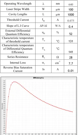
Table 1. AlGaInP Laser Diode Model Parameters
Operating Wavelength nm 640
Laser Stripe Width W m 100
Cavity Lengths L m 1000
Threshold Current Ith A 0.075
Slope of L.I Curve ΔP/ΔI W/A 0.4
External Differential
Quantum Efficiency d % 52
Characteristic temperature
of threshold current To °C 131
Characteristic temperature of Differential Quantum
Efficiency
T °C
141
Series Resistance Rs 28
Internal Loss i cm-1
7.7
Reverse Bias Saturation
Current Is A 0.01
4 Table 2. VCSEL Model Parameters
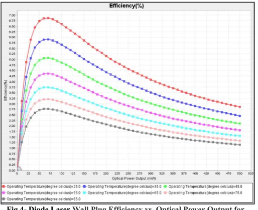
Fig.4- Diode Laser Wall Plug Efficiency vs. Optical Power Output for varying temperature
It is much clear from figure.3 that, wall plug efficiency varies significantly with optical power output. It increases with increasing optical power output until reaching a maximum value of 6.75% when the optical power is ~ 75mW, then its starts decreasing. For this range of 0-500mW of optical power output, there is a difference of 3.75% between maxima and last value in the range. Therefore when the optical output power varies significantly, this difference is not small enough to be tolerated. From figure.4 it can be seen that the wall plug efficiency decreases with increasing temperature. This is because laser threshold current increases with increasing temperature, laser differential quantum efficiency decreases with temperature and the diode voltage increases with temperature. As a result the wall plug efficiency decreases with increasing temperature.
B. VCSEL Laser
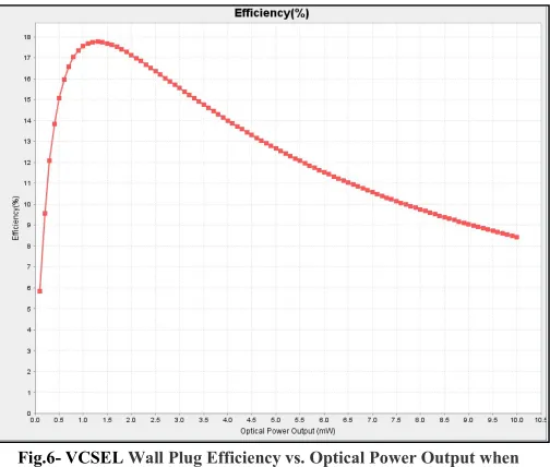
A single mode InGaAs–GaAsP quantum well VCSEL model is used for simulating the variance in wall plug efficiency. The parameters of the VCSEL model are tabulated below (Table 2) [6], [9]. The wall plug efficiency of VCSEL behaves similarly to that of the diode laser, with increasing optical power output (fig.6). The maximum wall plug efficiency was found to be 17.750% at optical power of around 1.3mW, when operating at 25ºC. As expected the efficiency decreases with increasing temperature (fig.5). The simulated efficiency values for both the laser sources were found to be close to the industry standards: edge emitted diode lasers (~10%) and VCSELs
(~20%) [11]. Fig.5- VCSEL Wall Plug Efficiency vs. Optical Power Output at varying
temperature. Operating
Wavelength λ nm 850
External Differential
Quantum Efficiency d % 50
Characteristic temperature of Differential Quantum Efficiency
Th °C 131
Series Resistance Rs W 150
Internal Quantum
Efficiency i % 70
Characteristic temperature of Differential Quantum Efficiency
Th °C 140
Forward Voltage V V 2.1
Minimum Threshold Current
Ith mA 0.918
Minimum Threshold Current
corresponding temperature
°C 46.13
Threshold current change with temperature
Fig.6- VCSEL Wall Plug Efficiency vs. Optical Power Output when T=25ºC.
VI.EFFECT ON OPTICAL LINK
A. Laser Source Sharing for optimal wall plug efficiency It can be seen in fig.3 that, a laser source outputs a specific optical output power at its maximum efficiency. Thus, depending on the optical power required per λ and the laser technology used, it may be beneficial to share the laser source power across two or more waveguides. Fig.7 shows a laser source sharing technique through coupler and splitter. A coupler first couples the light waves from a set of laser sources (each emitting one λ), and the splits the light into multiple waveguides. If the diode laser simulated above is used as the laser source, for a total optical power output required per wavelength of 1mW, if a laser source per wavelength per waveguide is used, this results in a laser source efficiency of 0.4%. If we share the laser source across two waveguides, the efficiency increases to 0.78%, because the total optical power output increases. Taking splitter loss (1.04mW) into account, Fig.8 shows how laser efficiency varies with required optical power per wavelength for different number of shared waveguides. It can be seen that for 1mW optical power output per wavelength, sharing the diode laser across 38 waveguides provides maximum efficiency of 6.8%.
Fig.8- Effective wall plug efficiency vs. Optical Power Output per wavelength for varying number of shared waveguides
Fig.9 Number of shared waveguides for optimal laser efficiency vs. Optical Power Output per wavelength for varying number of shared
waveguides
B. The number of shared waveguides to achieve optimal wall plug efficiency
Mathematically, the number of shared waveguides that will result in a laser diode operating at its maximum wall plug efficiency is derived by,
Fig.7- Laser Source being sharing through couplers and splitters [3] Table 3. Laser source sharing Parameters
𝑆𝑚𝑎𝑥 = 𝐼𝑁𝑇 [
𝑃𝑜𝑢𝑡𝑀𝑎𝑥
𝑃𝑜/λ + 𝐿𝑜𝑠𝑠𝑝𝑒𝑟𝑠𝑝𝑙𝑖𝑡
𝐶 𝑃𝑜𝑢𝑡𝑀𝑎𝑥 = √
𝑎(10) 𝑐 = 𝐼𝑡ℎ2𝑅𝑠 + 𝐼𝑡ℎ𝑉𝑑 (11)
] (9)
𝑎 = 𝑅𝑠 𝐾 (12)
𝐾 = η𝑖 η𝑑ℎ𝑐
λq (12)
Splitter Loss 1.04mW/split
Optical Power output
6 Smax is the number of shared waveguides corresponding to the
laser’s maximum wall plug efficiency.PoutMax is the laser’s
optical power output at which this maximum wall plug efficiency is obtained.𝑃𝑜/λ is the optical power output per
wavelength. Losspersplit is the optical splitter’s loss/split
(𝑚𝑊/𝑠𝑝𝑙𝑖𝑡) .It should be noted that the operating temperature
Table 4. Laser source power budget for the Clos Network
should be taken into account for the case of 𝐼𝑡ℎ , η𝑑 and 𝑉𝑑. Fig.
9 shows that the number of shared waveguides that will result in the laser source operating at an optimal wall plug efficiency for varying optical power output per wavelength. It confirms the previous findings for this laser diode model, that at 1mW of optical power output per wavelength, the optimal number of shared waveguides is ~38. It should be noted that the optical power output per wavelength should take into account the waveguide propagation loss which will depend on the length of the waveguide and the waveguide loss coefficient (dB/cm). It should be kept in mind that, this is a mathematical
approximation, in reality other physical parameters needs to be taken into account (e.g. crosstalk, reflection, laser source placement etc.) for deciding an optimal number of waveguides shared by a laser source.
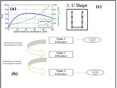
VII. EFFECT ON LASER SOURCE SHARING AND PLACEMENT STRATEGY FOR NETWORK ON CHIP (NOC) A. Laser Source Sharing across various logical topologies A case study is presented to show how the variance of wall plug efficiency should be applied in deciding the sharing and placement of laser sources in a Network on Chip (NoC), and in the physical layout. For the analysis it is assumed that the target system bisection bandwidth is always 512 GB/s and all cores are consuming 0.7 W of power. Fig.10 (a) shows the wall plug efficiency vs. optical power output for the laser source used. An 8 array 3 stage Clos network topology is used for the analysis of the laser source placement. Fig.10 (b) shows the number of routers and photonics channels used for the network stages’ connections. The first and third stages are connected to 32 cores (4 cores/router). The photonics channels are mapped to a U-shaped layout (Fig.10 (c)) [3].
Fig.10- (a) Wall plug efficiency vs. Optical output power by the laser source [3]. (b) Clos Network topology layout. (c) Photonic channel share [3].
(b)
(c) (a)
8 array 3 stage Clos network
Number of routers 8x3 24
Waveguide Loss 2dB/cm
Wavelength/channel 16
Number of
Channels 64+64 128
Concentration 4
No Laser Source Sharing Number of shared
channels/laser source 0 Optical Output power per wavelength 0.15mW Wall-Plug efficiency @ 0.15mW 0.12% Electrical Input Power per laser source
0.15mW/0.12% 125mW
Number of laser sources 16(wavelength) x 128(channels) 2048 Total Electrical Power required
2048 (laser sources) x 125mW
256 W
Laser Source Local Share Number of shared
photonic channels/ laser source 16 Optical Output power per wavelength 0.15mW Optical Output power per laser source 0.15mW x16 waveguides 2.4mW Wall plug efficiency @ 2.4mW 1.30% Electrical Input Power per laser source
2.4mW/1.30% 185mW
Number of laser sources (128/16) (channels) x16 wavelengths 128 Total Electrical Input Power
185 mWx128 laser source
23 W
Laser Source Edge Share Number of shared
photonic channels/laser source 128 Optical Output power per wavelength 0.18mW Optical Output Power per laser source 0.18mW x128 waveguides 23.04mW Wall plug Efficiency @ 23.04mW 6.38% Electrical Input Power per laser source
23.04mW/6.38% 361mW
Number of laser
sources (128/128)(channels)x1 (wavelength) 16 Total Electrical
Input Power
361 mWx16 laser source
Table 4 describes how the placement and sharing of laser sources on a Network on chip (NoC) changes the wall plug efficiency and hence the total electrical power consumption. If no local sources are shared, the efficiency for each local source is 0.12% which corresponds to a total electric power consumption of 23 W. Given that the 1st, 2nd and 3rd stages are
placed next to each other, it is possible to share the laser sources. When the laser source is shared among 16 photonic channels, the total optical power output increases and thus the wall plug efficiency increases. This corresponds to a much lower electric power consumption of 23W. When the laser source is placed along the edge, the optical power output required for each waveguide increases to 0.18mW because the length of the waveguide increase. If 16 laser sources (1 for each wavelength) are shared across the 128 photonic channels, the total wall plug efficiency rises to 6.38%, which
corresponds to a total electric power consumption of 5.77W. This sharing strategy results in the laser source operating at optimal efficiency and the lowest power consumption for the network [3].
VIII. CONCLUSION
It should be taken into account that the true wall-plug
efficiency should take into account the power dissipated in the heat sink and not only the electric power supplied to the laser source. Even though in this project, the heat sink power dissipation have not been taken into account, it provides the fundamental variance of laser wall plug efficiency with optical power output. The project concludes that the wall plug efficiency of a laser source is maximum at a certain optical power output and after this optimal optical power output is reached, the efficiency starts to decrease with increasing optical power output. It varies significantly with the laser operating temperature, which should always be taken into
account for determining the wall plug efficiency. For optical links, sharing a laser source across multiple waveguides, may provide certain advantages and increase the effective wall plug efficiency. However, it is important to keep in mind the cost of sharing (crosstalk, reflection, polarization etc.), may sometimes be greater than the increase in wall plug efficiency. For the placement and sharing of laser sources on a Network on Chip, the variance in wall plug efficiency should be taken into account in selecting an optimized placement and sharing strategy that will provide the maximum efficiency and lowest electric power consumption.
REFERENCES
[1] N. P. Barnes, “Solid-state lasers from an efficiency perspective”, IEEE J. Sel. Top. Quantum Electron. 13 (3), 435 (2007).
[2] Newport, Application note No.1, pp.2-7.
[3] C.Chen et.al, “Sharing and Placement of On-chip Laser Sources in Silicon Photonic NoCs, Eighth IEEE/ACM International Symposium on Networks-on-Chip(NoCS),pp-88-95,2014.
[4] B.Van Zeghbroekc, “Principle of Semiconductor Electronics”, University of Colarado, 2011.
[5] R. Michalzik , J.Ebeling, “Opreating Principles of VCSELs”. University of Ulm, Optoelectronics Department, D-89069 Ulm, Germany, 2011. [6] C.Chen et.al, “Temperature Analysis of Threshold Current in Infared
Vertical-Cavity Emitting Lasers”, IEEE Journal of Quantum Electronics, Vol.42, No.10, pp.1078-1082, October 2006.
[7] Finiser, Application note VCSEL, pp.1-15.
[8] C.Wilmsen et.al, Vertical Cavity Surface Emitting Laseres, Cambridge University press, November 2001.
[9] Finiser, Product Guide, pp.1-8.
[10] Opnext, ODE2011-00 (M),pp.1-4, August 2008.
[11] J.Tatum, “VCSELs in Varius Sensor Applications”, Proceedings of Sensor Expo, 2005.