Page 46 www.ijiras.com | Email: [email protected]
PLCC Communication Using AVR Microcontroller for Smart
Fault Detection
Churaman Sahu
M. Tech. Scholar, SSGI, Bhilai, Chhattisgarh
Prof. Simardeep Kaur
Assistant Professor, SSGI, Bhilai, Chhattisgarh
I. INTRODUCTION
Power line carrier communication is the use of power line carrier communication as a transmission channel, the power system is a unique form of communication. The idea of sending communication signals on the same pair of wires as are used for power distribution is as old as the telegraph itself, the number of communication devices installed on dedicated wiring far exceeds the number installed on AC mains wiring. In the 1920‟s at least two patents were issued to the American Telephone and Telegraph Company in the field of “Carrier Transmission over Power Circuits”. United States Patents numbers 1,607,668 and 1,672,940, filed in 1924 show systems for transmitting and receiving communication signals over three phase AC power wiring. It is based on the frequency shift, frequency division principle, the original signal modulates the carrier, move to a different line transmission band to the power line transmission. Since the frequency is generally used for communication over a few hundred KHz, thus avoiding interference with current of 50Hz frequency. This means of communication, compared with less
investment, short construction period, simple equipment, communications security, real-time, no long distance relay and communication and a series of advantages. Power line carrier communication is one kind of communications that makes use of power line to transfer the data, voice, media and other signals. Power line carrier communication technology has the properties of high economic value, universality and practicability. With the rapid development of power electronics technology, switching power supply is widely used in power line communication equipment. Switching power supply becomes the key infrastructure of communications equipment and maintains a stable output voltage. Switching power supply controls the time ratio of the electronic switching device opened and shut off and electronic switching device modulates the pulse of the input voltage. Factors of switching power supply that affect the power line communication are Phase Noise, and Electromagnetic Interference. With the worldwide existing power grid infrastructure, power line communication (PLC) technology has received a renewed attention in the last decades. At the same time, applications based on this technology attract a lot
Abstract: The idea of sending communication signals on the same pair of wires as are used for power distribution is as old as the telegraph itself, the number of communication devices installed on dedicated wiring far exceeds the number installed on AC mains wiring. Commercial spread spectrum power line communication has been the focus of research and product development at a number of companies since the early 1980’s. After nearly two decades of development, spread spectrum technology has still not delivered on its promise to provide the products required for the proliferation of power line communication. The idea of communication over power line has to be taken care of for the future prospects of communication. In the view of this we conceive the idea to communicate the information regarding the status of the power line to the sub-station. The development of the conceived idea needs full command and understanding of the technology and for this purpose a survey has been done in this paper showing the basic existing method for communication, its advantages and the drawbacks.
Page 47 www.ijiras.com | Email: [email protected] of commercial interests, such as Smart Grid, automatic meter
reading (AMR), advanced metering infrastructure (AMI), etc. For the indoor environment, in addition to electricity delivery, power grids are also often used as medium to support local area networks (LAN). However, this type of indoor PLC channel has demonstrated hostile characteristics for broadband communications [1], which mainly consist of four aspects: (1) high attenuation in high-frequency (HF) band; (2) frequency selective fading in all available band; (3) time-varying property with different time scales; (4) considerable non-white Gaussian noises. To achieve communication between any two points, several paths are available. However, of lately the traditionally used channels have come to a saturation level and there was need to explore new kind of technology which is simpler to implement and is not as expensive as other related technologies. The basic idea of power line carrier communication system (PLCC) is to use the existing power cable infrastructure for communication purpose. The system can be implemented in small areas such as residences, offices, etc. and with the use of this system; various kind of devices can be controlled remotely. The main benefit of this system stands to the residential users of making their dream of automation of their house. With just a simple set up of a transmitter and receiver, and ensuring equal phase supply, one can control a host of devices and enjoy the leisure of living in a fully automated house. The external electrical grid can also be used for many applications whose solutions provide many opportunities for equipment vendors and utilities to offer new services, features and products, cut costs of current services, fully automate manual processes and procedures. It can also be used to improve current products, monitor and collect valuable data, offer remote service options and create new business and revenue streams utilizing the existing infrastructure [1].
II. RELATED WORK
Communication over the Power Line is an important are where precautions need to be taken as 230/240 V is used for communication and any ignorance may cause a heavy damage. Further the technique used for relaying the data or information on the transmission line have its own technique which also should be understood clearly. In the view of such requirement a review of the previous related work has been done and is represented below.
Guosheng Li in his paper analyzes the characteristics of a high-frequency signal transmission power lines focused on the spread spectrum communication technology in power line carrier communication. The author presents a depth study of the spread spectrum modulation and demodulation techniques in communication technology, high-performance power line carrier dedicated MODEM chip SSC P300 and other internal works which focuses on the design of the concentrator hardware systems. The author concentrated on automatic meter reading system and designed a power line carrier meter concentrator. The design of the proposed system consists of four modules namely (1) Power Line Carrier remote meter reading system concentrator hardware design, (2) concentrator design master, (3) Extended data memory and (4) Clock
Module. On these aspects of the modules the author informs that the concentrator itself is composed of part of the control unit, the database storage unit, a clock unit, a carrier communication unit , the communication unit the data transfer and the like. Concentrator only does PC slave, but also a host carrier meter, its hardware and software design requirements to ensure system reliability and stability for all. In the concentrator design, both SCM and PC communicate, but for communication and the telephone network we need two serial ports. W77E58 is a fast 8051 compatible microcontroller; its core redesigned to improve the clock speed and memory cycles. The author informs that W77E58 can run at lower clock frequencies. W77E58 contains 32KB Flash EPROM, operating voltage of 4.5V-5.5V, with 1KB on-chip external data memory when the user application using on-chip SRAM instead of external SRAM, can save more I / O ports.
Page 48 www.ijiras.com | Email: [email protected]
Figure 1: Typical damages that may happen on the OPGW: (a) strand break by lightning stroke; (b) collapse of transmission towers caused by ice-covering on transmission
lines
To simulate the strain effect caused by ice covering on OPGW, a tensile force loading apparatus is constructed to change the tensile force loaded on the OPGW, which replaces the weight of ice. Additionally, a vibration generator is used to analyze the influence of OPGW vibration on both the temperature and strain measurement. Typically, optical fiber ground wire (OPGW) is used for electric power system communication and it undertakes most of the electric power communication business, which is vital for the healthy operation of electric power grid. Fig. 2 shows a typical construct of the OPGW. The inner part is optical fiber unit which is protected by the steel tube, and the space between the optical fiber unit and the steel tube is filled with jelly in case of chemical erosion and other damages. In the same way, the space between the aluminum-clad steel wires and the steel tube is filled with grease. The aluminum-clad steel wires are used as the earth line and the optical fiber unit is for the use of communication.
Figure 2: A typical OPGW structure
Liang et al. introduces the power line carrier communication technology and switching power supply, and expounds the factors that affect the switching power supply for power line communication, analyzes how to solve the problem of switching power supply in power line communication, such as analysis of phase noise electromagnetic interference on the impact of switching power supply, and proposes measures to perfect the switching power supply. The author mainly introduces the characteristics of switching power supply, and the OFDM which is the main modulation way of the power line carrier communication. Besides, it introduces the impact of noise on OFDM, electromagnetic interference on the impact of communication, and the way to improve the effect of the power line communication. Author says factors of switching power supply affect the power line communication as discussed below. The main factor that influences the performance of broadband power line communication is the physical layer modulation technique which is used as the core chip of power line communication equipment. The broadband power line communication modulation technology is based on the Orthogonal Frequency Division Multiplexing (OFDM). OFDM system requires a strict inter-subcarrier orthogonal, it is particularly sensitive to the phase noise and susceptible to phase noise, which is one of its major drawbacks. Phase noise of OFDM systems has two interferences: One is the common
phase error (CPE), all the sub-carriers in the OFDM symbols will produce the same phase error. The other is Inter-carrier Interference (ICI), which will make the symbol constellation points rotate and diffuse by the phase noise, lead to destruction of orthogonality between subcarriers, causing inter-carrier interference. The power supply often used in the power line communication devices switching will produce output noise, radiation noise, background noise and other noise in the power line communication device, phase noise is a random fluctuation of the output signal phase due to various noise effects in the system. Therefore, the phase noise of switching power supply will affect OFDM systems, and thus will reduce broadband power line communication performance. Electromagnetic interference is produced in the power line communication devices by the switching power supply. The main component of the electromagnetic interference is the interference source, coupling path, the receiver, each element is a necessary condition for electromagnetic interference effects.
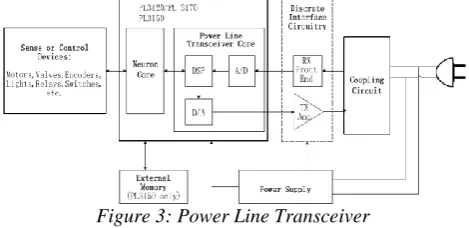
Ke Ma et al. briefly introduce the power line carrier communication and field bus technology on Lon Works. The research on Application on Lon Works in temperature measurement system introduces how to use PL3120 to design a two temperature measuring system based on power line carrier communication of Lon Works from the aspect of software and hardware. Power line carrier communication network on Lon Works is modulating the communication data into a carrier signal or spread spectrum signal through the power line transceiver. Then connect it to the power line through the coupler. The benefits to do so are to carry out data communication by the existing power line which reduces the tedious wiring of communication greatly. The structure diagram of power line transceiver is shown in figure 3.
Figure 3: Power Line Transceiver
Page 49 www.ijiras.com | Email: [email protected] transceiver makes the power line becoming a reliable line for
data transmission.
III. METHODOLOGY
Use of PLCC in modern electrical power system is mainly for telemetry and telecontrol. Tele means remote. Telemetry refers to science of measurement from remote location. PLC Modem are the transmitter and receiver device and is responsible of converting the data so that it can be uploaded to the transmission line. PLC Transceiver is the key component of a PLCC system. It is the device which transmits & receives data to & from the power lines and acts as a hub between the power stations and our Computers/Network utilization devices. They are wired with the electrical voltage lines at home or business and work on two modes – transmit mode and receive mode. In transmit mode, they simply receive data from receiver end installed on the same network and further transmit them. In receive mode, they work the opposite way. A number of companies provide PLC transceivers and other networking devices for PLCC communication. A PLC transceiver is shown in the following image.
Figure 4: PLCC Panel Block Diagram
Each end of transmission line is provided with identical PLCC equipment consisting of equipment: (1) Transmitters and Receivers, (2) Hybrids and Filters, (3) Line Tuners, (4) Line Traps, (5) Power amplifier, (6) Coupling capacitors.
Signal propagation along high voltage lines depends entirely on the construction of transmission lines, mainly on the configuration and characteristics of all conductors and on the ground resistance optimum coupling allows to make the best use of a given transmission line. Transposition may introduce additional attenuation which can generally not be predicted with simple rules. Most transposition schemes result in high attenuation poles at certain frequencies such frequencies cannot be used for PLC communications. The proposed system utilizes the concept of PLC Modem and implements the PLCC over the transmission line for the detection of fault or any misuse (theft) of current. The basic block diagram of the proposed system is shown below:
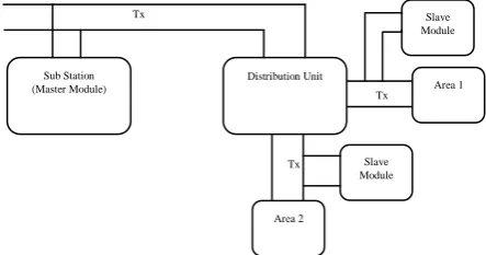
Figure 5: Block Diagram of the Proposed System
IV. RESULT
As can be seen in the above section the master module receives and transmits the necessary information over the transmission line. The Simulation of the proposed work reviles that the proposed system can be used for fault management in the transmission line and is very helpful in fast and accurate detection of the faults in the transmission line. The Proteus design and simulation of the modules are shown below and the design of hardware is our future work.
Figure 6: Proteus Design of Master Module
Figure 7: Proteus Design of Slave Module
V. CONCLUSION
A review of various technologies which can be applied to power line communication leads to the conclusion that the digital signal processing is key to overcoming the harsh conditions of the power line environment. Furthermore spread spectrum technology was found to be a detriment rather than a benefit in overcoming these challenges. Since no technology is static, one must ask whether the clear advantage demonstrated by DSP-based narrow band transmission will continue in the future. This question can only be answered with the benefit of research and extensive field experience with each technology. With all these information the conceived idea can be implemented as discussed in section 3 of this Literature. Last but not the least the hardware design of the proposed system will provide a relief and a support system to the system engineers to analyze and detect the fault in the transmission line fast and accurately.
ACKNOWLEDGEMENT
Working on Power Line Communication area needs high amount of information and knowledge. I hereby like to thank Tx
Line
Tx Line
Tx Line Sub Station
(Master Module)
Distribution Unit
Area 2
Area 1 Slave Module
Page 50 www.ijiras.com | Email: [email protected] all the authors whose paper directly or indirectly helped me to
understand the PLCC Communication technology.
REFERENCES
[1] Li MCS-51 series MCU practical interface technology [M] Beijing: Beijing University of Aeronautics and Astronautics Press, 1993.
[2] Zhang Xin Principles and Applications [M] Beijing: Electronic Industry Press, 2005.
[3] Tuo Huarong based on spread spectrum technology, power line modem design [D] Anhui: Hefei University of Technology, 2005.
[4] Jingjing research on power line carrier remote meter reading system [D]: Xi'an University of Science and Technology, 2006.
[5] Li Zhijun based on spread spectrum chip SSC P300 cell carrier automatic meter reading system [D], Wuhan: Wuhan University of Technology, 2005.
[6] Yi dragons. Applications in power line carrier communication technology in remote automatic meter reading system [J]. Applied Science and Technology, 2001, 28(1):17 -18.
[7] Pan superior chip control technology in communications applications MCS-51 [M] Beijing: Electronic Industry Press, 2008.
[8] Pan Lizhen applied research [D] on the remote meter reading system concentrator power line carrier communication technology Taiyuan: Taiyuan University of Technology, 2005.
[9] LIU Si- long, WANG development based on P300 chipset power line carrier communication module [J]. Appliances and instruments, 2003, 40 (456):37-41.
[10]Kang Guanghua Electronics Technology -based analog part (5th edition) [M] Beijing: Higher Education Press, 2006.
[11]Stanley H. Horwitz, Arun G. Phadke, Power System Relaying, Third Edition, John Wiley and Sons, 2008 ISBN 0-470-05712-2, pages 64-65
[12]Edward B. Driscoll, Jr. ‗The History of X10„
[13]Y. Koren, Y. Seri ― using LIN over power line communication to control truck and trailer backlights‖ – SPARC 2007.
[14]K Dostert, Telecommunications over the power distributed possibilities and limitations proc 1997 internet. Symp. On power line comms and its applications, pp 1-9. [15]T. N. Buti, S. Ogura, N. Rovedo, and K. Tobimatsu, “A
New Asymmetrical Design for Reliability and Performance,” IEEE Trans. on Elec. Dev, vol. 38, pp. 1757-1764, 1991.
[16]A. Akturk, N. Goldsman, and G. Metze, “Faster Inverter Switching Obtained with Channel Engineered Asymmetrical Halo Implanted,” Semi. Dev. Res. Sym, pp. 118-221, 2001.
[17]A. eHaidine, H. Hrasnica, and R. Lehnert, “Broadband Powerline Communications: Network Design,” pp. 110-150, 2000.