A New Control Algorithm for Doubly Fed
Induction Motor with Inverters Supplied by a PV
and Battery Operating in Constant Torque
Region
Sheenu V S Jomole Joseph P
PG Student Assistant Professor
Department of Electrical & Electronics Engineering Department of Electrical & Electronics Engineering Mar Baselios College of Engineering and Technology,
Trivandrum India
Mar Baselios College of Engineering and Technology, Trivandrum India
Abstract
This algorithm enables the DFIM to operate in a wide range of speed variation. This structure gives to the machine the capacity to operate up to twice its rated power. The power density is improved here .Efficiency of DFIM is controlled. When this algorithm is applied in a DFIM, the total system has less dependence on motor parameters than other type of control algorithms. This is widely used for the application of Electric Vehicles.
Keywords: Doubly Fed Induction Motor (DFIM), Electric Vehicle/Hybrid Electric Vehicle (EV/HEV), PV Array (Photovoltaic Array)
________________________________________________________________________________________________________
I. INTRODUCTION
Nowadays, when variable-speed drives are used for industrial applications, there is a requirement of increasingly important performance and a maximum reliability and minimum cost. Currently the use of AC machines is becoming more common as these machines are characterised by their robustness and longevity compared to commutator machines.
There is great interest in the Doubly-Fed Induction Machine (DFIM) for various applications: as a generator for wind energy and for other various industrial applications, such as rolling and traction or propulsion systems.
Out of these, Doubly-Fed Induction Motor (DFIM) is widely accepted as the most potential candidate for Electric Vehicle/ Hybrid Electric Vehicle applications.
However, the objective of this work is to operate the DFIM in a wide range of speed variation for the application in Electric Vehicle. Here, the machine is connected through two power converters with Pulse Width Modulation (PWM) control, these converters are both powered by a battery, which is a key element for development of electrical vehicles, namely the energy density is low and the charge time is very long.
The advantage of the power structure chosen is not only to operate the machine in a wide range of speed variation, but also to give to the machine the capacity to operate up to twice its rated power. So the power density is improved. Also the DFIM have the ability to start with high torque.
For the power transfer between the battery and the DFIM, the power electronic converters are sized 100% of rated power of the machine. These power electronic converters are bidirectional converters with PWM control, they absorb power from the battery when the machine operates as a motor and they provide to it when the machine operates as a generator during braking. Here, the power converters are IGBTs.
This work is for the study and control of drive train of an electric vehicle based Doubly-Fed Induction Machine (DFIM). A power structure and a new control strategy is applies which allow to operate over a wide range of speed variation, for both applications: engine and recovery. So the power of the machine can reach twice its rated power. The results show the good performance of the Direct Torque Control, applied to the DFIM.
II. CONTROL STRATEGY OF DFIM
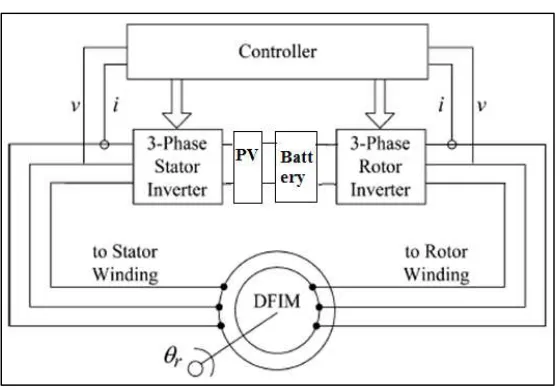
Fig. 1: DFIM drive system using PV and Battery
Modelling of PV and Battery is given in the next section.
The dynamic equations for the modelling of DFIM are given below.
𝑉𝑑𝑠= 𝑅𝑠𝑖𝑑𝑠+ 𝑑𝜆𝑑𝑠
𝑑𝑡 − 𝜔𝑠𝜆𝑞𝑠 (2.1)
𝑉𝑞𝑠 = 𝑅𝑠𝑖𝑞𝑠+ 𝑑𝜆𝑞𝑠
𝑑𝑡 − 𝜔𝑠𝜆𝑑𝑠 (2.2)
𝜆𝑑𝑠= 𝐿𝑠𝑖𝑑𝑠+ 𝐿𝑚𝑖𝑑𝑟 (2.3)
𝜆𝑞𝑠 = 𝐿𝑠𝑖𝑞𝑠+ 𝐿𝑚𝑖𝑞𝑟 (2.4)
𝑉𝑑𝑟 = 𝑅𝑟𝑖𝑑𝑟+ 𝑑𝜆𝑑𝑟
𝑑𝑡 − 𝜔𝑟𝜆𝑞𝑟 (2.5)
𝑉𝑞𝑟 = 𝑅𝑟𝑖𝑞𝑟+ 𝑑𝜆𝑞𝑟
𝑑𝑡 + 𝜔𝑟𝜆𝑑𝑟 (2.6)
𝜆𝑑𝑟= 𝐿𝑟𝑖𝑑𝑟+ 𝐿𝑚𝑖𝑑𝑠 (2.7)
𝜆𝑞𝑟= 𝐿𝑟𝑖𝑞𝑟+ 𝐿𝑚𝑖𝑞𝑠 (2.8)
𝑇𝑒= 1.5𝑝
𝐿𝑚
𝐿𝑠
(𝜆𝑞𝑠𝑖𝑑𝑟− 𝜆𝑑𝑠𝑖𝑞𝑟) (2.9)
𝜔𝑚𝑟=
1 𝑝𝜔𝑒𝑟=
1
𝑝(𝜔𝑠+ 𝜔𝑟) (2.10)
Table – 1
Shows the rating and parameters of DFIM.
Parameter Rated values
Power(kW) 30
Voltage(V) 415
Current(A) 100
Number of poles 4
Frequency(Hz) 50
Speed(rpm) 1500
Torque(Nm) 191
Nominal stator phase current 3.6A Nominal rotor phase current 6.0A
Stator/rotor resistance 0.0067/0.0399Ω Stator/rotor leakage inductance 7.468/ 52.006mH
Mutual inductance 164.6mH
III. MODELLING OF BATTERY
A Generic battery model is modelled here. The model uses only the battery SOC (State Of Charge) as a state variable in order to avoid the algebraic loop problem and can accurately represent four types of battery chemistries including lead acid battery.
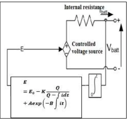
The modelling is attempted using a simple controlled voltage source with a constant resistance as shown in fig.3, where the controlled voltage source is described through eqn. (4).
𝐸 = 𝐸0− 𝐾
𝑄
𝑄 − ∫ 𝑖𝑑𝑡+ 𝐴𝑒𝑥𝑝 (−𝐵 ∫ 𝑖𝑑𝑡) (1) 𝑉𝑏𝑎𝑡𝑡= 𝐸 − 𝑅𝐼𝑏𝑎𝑡𝑡 (4)
E0= no − load battery voltage (V); K = polarization voltage (V);
Q = battery capacity (Ah);
∫idt= Charge drawn/supplied by the battery (Ah); A = exponential zone amplitude (V);
B = exponential zone time constant inverse (Ah−1);
Vbatt = battery voltage (V);
Rbatt = internal resistant (Ω);
Ibatt = battery current (A);
Fig. 2: Generic battery model.
This model is based on some assumptions:
1) The temperature doesn’t affect the models behaviour. 2) The self- discharge of the battery is not represented. 3) The battery has no memory effect.
4) The capacity of the battery doesn’t change with the amplitude of current.
5) The models parameters are deduced from the discharge characteristics and assumed to be the same for charging. 6) The internal is supposed constant during the charge and discharge cycles and doesn’t vary with the amplitude of current.
IV. DIRECT TORQUE CONTROL (DTC)
The basic principle of DTC is to directly select stator voltage vectors according to the torque and flux errors which are the differences between the references of torque and stator flux linkage and their actual values. The governing equation for torque for this scheme is due to the interaction of stator and rotor fields. Torque and stator flux linkages are computed from measured motor terminal quantities i.e. stator voltages and current. An optimal voltage vector for the switching of Voltage Source Inverter (VSI) is selected among the six non-zero voltage vectors and two zero voltage vectors by the hysteresis control of stator flux and torque.
The conventional DTC scheme is a closed loop control scheme, the important elements of the control structure being: the power supply circuit, a three phase voltage source inverter, the doubly fed induction motor, the speed controller to generate the torque command and the DTC controller. The DTC controller again consists of torque and flux estimation block, two hysteresis controllers and sector selection block, the output of the DTC controller is the gating pulses for the inverter.
DTC is one method used in variable frequency drives to control the torque and speed of three-phase AC electric motors. This involves calculating an estimate of the motor’s magnetic flux and torque based on the measured voltage and current of the motor.
V. VEHICLE DYNAMICS
The equation governing vehicle dynamics is given as following:
𝑇𝑟= (𝐹𝑟+ 𝐹𝑎𝑟𝑑+ 𝐹𝑔)𝑟 + 𝛿𝑀𝑣
𝑑𝑉𝑣
𝑑𝑡 (5.1) 𝐹𝑟= 𝑃. 𝐶𝑟 (5.2)
𝐶𝑟= 0.01 (1 +
𝑉𝑣
100) (5.3)
Where 𝐶𝑟 is called the rolling resistance coefficient and P is the normal load on the wheel.
Where ρ is the air density, Af is the frontal area of the vehicle, Cd is the aerodynamic coefficient, Vv is the vehicle speed and Vw is the wind speed.
Fg= Mvg sin(α) (5.5) Where g is the earth gravity and 𝑀𝑣 is the total weight of the vehicle.
VI. SIMULATION AND RESULTS
Simulation
Fig. 3: DTC on both stator and rotor side with air-gap flux control
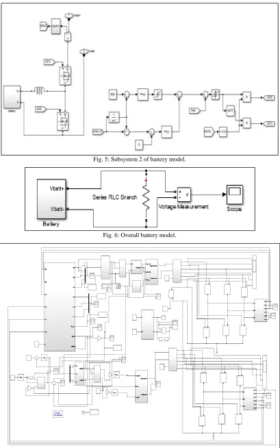
Fig. 5: Subsystem 2 of battery model.
Fig. 6: Overall battery model.
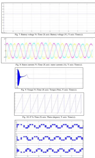
Results
Fig. 7: Battery voltage Vs Time (X-axis: Battery voltage (V), Y-axis: Time(s)).
Fig. 8: Stator currents Vs Time (X-axis: stator currents (A), Y-axis: Time(s)).
Fig. 9: Torque Vs Time (X-axis: Torque (Nm), Y-axis: Time(s)).
Fig. 10: 𝜃 Vs Time (X-axis: Theta (degree), Y-axis: Time(s)).
Fig. 12: Line voltages Vs Time at the stator side (X-axis: Line voltage (V), Y-axis: Time(s)).
Fig. 13: Phase voltages Vs Time at the rotor side (X-axis: Phase voltage (V), Y-axis: Time(s)).
Fig. 14: Line voltages Vs Time at the rotor side (X-axis: Line voltage (V), Y-axis: Time(s)).
VII.CONCLUSION
The modeling and control of DFIM has been carried out for Electric Vehicle/Hybrid Electric Vehicle application. The DFIM has been found capable to work for extended constant torque region which has been shown in simulation results. A Direct Torque Control (DTC) is applied to both stator and rotor side. SVPWM Inverter is provided for both stator and rotor side which is supplied by a PV and a Battery.
REFERENCES
[1] Yu Liu, student member, IEEE, and Longya Xu, fellow,IEEE, “The dual- current -loop controlled Doubly Fed Induction Motor for EV/HEV Applications” IEEE Transactions On Energy Conversion,Vol.28,no.4,pp.1045-1052,Dec2013.
[2] G. Pellegrino, A. Vagati, B. Boazzo, and P. Guglielmi, “Comparison of induction and PM synchronous motor drives for EV application including design examples,” IEEE Trans. Ind. Appl., vol. 48, no. 6, pp. 2322–2332, Nov./Dec. 2012.
[3] M. Zeraoulia, M. E. H. Benbouzid, and D. Diallo, “Electric motor drive selection issues for HEV propulsion systems: A comparative study,” IEEETrans. Veh. Technol., vol. 55, no. 6, pp. 1756–1764, Nov. 2006.
[4] Y. Kawabata, E. Ejiogu, and T. Kawabata, “Vector-Controlled double inverter-fed wound-rotor induction motor suitable for high-power drives,”IEEE Trans. Ind. Appl., vol. 35, no. 5, pp. 1058–1066, Sep./Oct. 1999.
[5] F. Bonnet, P. Vidal, and M. Pietrzak-David, “Dual direct torque control of doubly fed induction machine,” IEEE Trans. Power Electron., vol. 54, no. 5, pp. 2482–2490, Oct. 2007.
[6] L. Xu and Y. Liu, “Comparison study of singly-fed electric machine with doubly-fed machine for EV/HEV applications,” in Proc. IEEE Int. Conf.Elect. Mach. Syst., 2011, pp. 1–5.