Design Of Stepper Motor Control Interface With Embedded
Systems
Eray Yılmazlar
1, Volkan Erdemir
2, Hilmi Kuşçu
3, Aydın Güllü
4 1-2(Kırklareli University, Technical Sciences Vocational School, Kırklareli, TURKEY)3(Trakya University, Mechanical Engineering Department, Edirne, TURKEY) 4(Trakya University, İpsala Vocational School, Edirne, TURKEY)
Corresponding Author: Eray Yılmazlar
ABSTRACT: In this study, the interface design which can be controlled in real time by the step motors which are widely used in the industrial area has been realized. For the purpose of the realized project, the use of the interface screens of the embedded system cards, which can see the same task instead of expensive industrial organs, has been realized. In the interface screen, the design for stepper motor cycle, number of steps, direction and speed control is created. The experimental set is designed to control for different stepper motors on the 7” display with raspberry pi. Remote access is provided between the interface screen and raspberry pi via the Windows IOT operating system. The interface screen design was made with the Microsoft Visual Studio program and run on the touch screen. The real-time control of the stepper motors is performed according to the options in the interface. The commands of the options were transmitted to the stepper motor drivers with raspberry's general purpose input / output pins and motor control was carried out. This study is an example of the development of more innovative designs with remote access, touch screen control and the use of embedded system cards according to other motor control interface designs.
KEYWORDS: Stepper motor, Interface, Control, Embedded Systems
--- --- Date of Submission: 01-06-2018 Date of acceptance: 16-06-2018 ---
---I. INTRODUCTION
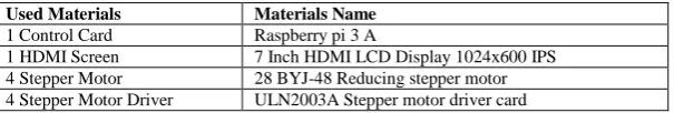
Today, the development of mobile devices, the remote communication of objects with the internet, the provision of control of devices and the preference of modern visual interfaces have also improved the interface designs[1, 2]. New generation interface designs have more modern visuals menus. It is developed in accordance with internet transfer and control of data. In order to perform these operations, the operating systems are re-quired. Among these devices, the Raspberry pi card comes to the forefront in terms of features and ease of use. The aim of this work is to realize the use of raspberry pi computer card and display panel which can realize more practical, economical and modern designs for the tasks performed by costly control units such as PLC, HDMI Panel and desktop computer. Another aim is to realize the control of the stepper motor and the parame-ters affecting this control via the interface. When used in design, engineering experiments, the use of stepper motor and learning of working characteristics will also occur[3]. The materials used in the figure 1.0 are shown in table I. The design was also controlled by raspberry pi on the IPS screen of 4 different stepper motors for rotation, step, direction and speed control.
Table I:Used Materials
A. Raspberry Pi 3 A
Embedded system cards are easy to use, low cost, accessible, and practical, increasing the use of single card computers in the industry and academies, as the operating system can be installed on them. In the figure 1 the raspberry pi 3A series, which appeared to be in the study, was used. The following Table II defines the Technical Specification of Raspberry Pi 1 Model A[4].
Used Materials Materials Name
1 Control Card Raspberry pi 3 A
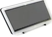
B. Interface Screen
The 7-inch HDMI LCD touch screen, shown in figure 2, was used in the study. Raspberry is connected with HDMI cable and is supplied with USB port. It has a screen resolution of 1024 × 600 and has a capacitive touch auditor.
Fig. 2: Interface screen
C. Step Motor
Step motors are brushless DC motors used in machines, robots, automation systems to convert electri-cal pulse signals into circular motion or liner motion. The stepper motor must be controlled by a stepper motor drive circuit in order to rotate by angular steps. Today, there are many driver cards and kits that perform this control process. Similarly, pulse signals can be generated by many units such as PLC, FPGA, Arduino, Raspber-ry pi. Step motors are usually made in two phases. Depending on the motor phase number and structure, the number of connectors can be 4, 5, or 6[5]. Step motor drive topology can be classified according to motor struc-ture. Drive topology of stepper motors is an important criterion for motor selection. There are two main topolo-gies in the application of stepping motors: unipolar and bipolar.
Bipolar step motor with four-pole stator comes from two windings (two-phase windings) divided into two parts in stepper motors. Bipolar stepping motors may have 4 winders or 6 tips with the lines removed in the middle of the two phase windings [6]
Unipolar step motor with unipolar winding, bipolar motors are formed as well as in the middle of two-phase windings. The midline line was connected to each other by 5, and 6 lines were formed without connect-ing. At the same time, the stator pole has windings which are not connected to each other but are wrapped in opposite directions. Figure 3 shows the schematic diagram of bipolar stepper motor and unipolar stepper motor
In the realized project, 4 pieces of 28BYJ-48 - 5V series Stepper Motor are used. This stepper motor is preferred because it has 5V supply preference because of 4 phase, speed variation ratio 1/64, stride angle 5.625 ° / 64, frequency 100Hz, low current draw and economical[7].
CPU 4× ARM Cortex-A53, 1.2GHz
GPU Broadcom Video Core IV
RAM 1GB LPDDR2 (900 MHz)
Networking 10/100 Ethernet, 2.4GHz 802.11n wireless
Bluetooth Bluetooth 4.1 Classic, Bluetooth Low Energy
Storage microSD
GPIO 40-pin header, populated
Ports HDMI, 3.5mm analogue audio-video jack, 4× USB 2.0, Ethernet, Camera Serial Interface (CSI),
Fig. 3: Schematic diagram of bipolar stepper motor and unipolar stepper motor
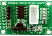
D. Step Motor driver
The stepping motor must be supplied with the appropriate supply voltage to the windings of the stator so that it can perform its movement. The sequence of phase signals required for the motor is provided by a con-trol circuit program. The ULN2003APG kit is shown in figure 4 as the drive circuit used in the design[8].
Fig. 4: ULN2003 Stepper motor driver
II. INTERFACE DESIGN IN ON MICROSOFT VISUAL STUDIO
Many interface panels have remote access, control card integrated touch screen structure. When these features are examined, it is observed that the interface applications of Microsoft Visual Studio respond to this need. The ease of use of these applications on control cards such as Raspberry pi, and the fact that it is economi-cal, increases the usage of panel and raspberry pi together in interface designs. The implemented interface de-sign was dede-signed as a windows application in visual studio. The dede-signed interface was communicated with the raspberry pi via the Remote Machine feature and the GPIO units of the card were controlled. The interface screen shown in figure created an integrated system by connecting to the 7inch touch screen with HDMI output of Raspberry Pi. In the interface design, it was created so that the characteristics of the stepper motor can be used in easy way. These features include number of revolutions, number of steps, speed of rotation, direction of rotation. There are 2 combo boxes on the interface screen. In these combo boxes, motor selection and rotation selection are made. There is also a text box that performs the rotation movement up to the desired number of steps instead of the rotation. The speed control of the stepper motor is performed with the slider set as the speed of rotation. The system is started with the forward and backward start buttons and is stopped with the stop but-ton. Figure 5 shows the interface screen design
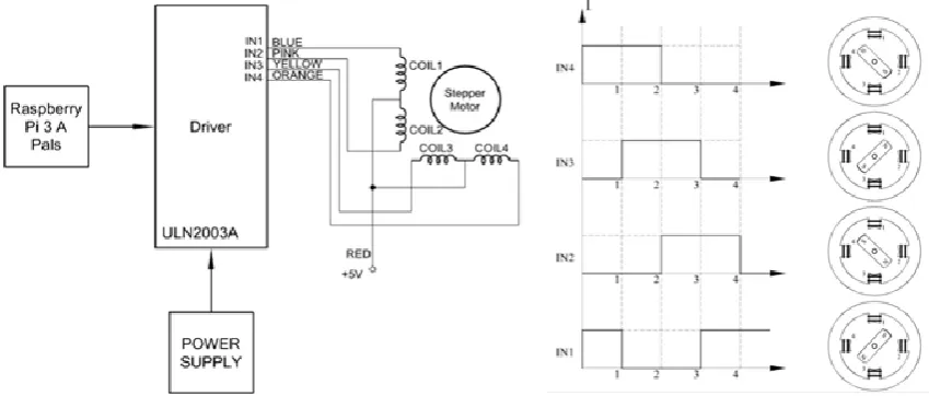
III. STEPPERMOTORCONTROL
Stepper motors can be controlled using an open-loop control system without stepping motors needing feedback[9]. The step that the motor will take is provided by applying the pulse (square wave) voltage to the windings in turn. With the pulse signal provided by the stepper motor driver, the desired angular displacement and direction of rotation of the motor can be controlled. The speed and acceleration control of the stepper motor can also be achieved by controlling the frequency of the pulse signal [10]. Figure 6 shows the square wave sig-nals produced by the motor driver and the rotational motion of the motor.
Fig. 5: Stepper motor control interface screen
The stepper motors perform the rotation according to the signals from the driver. If the rotation is represented by a formula, the relationship between the phase currents and the torque is given by the following equations.
Fig. 6: Square Wave Signals Produced By the Motor Driver and the Rotational Motion of the Motor
[ ( )] (1)
[ ( )] (2)
[ ( ) ( ) ]
(3)
(4)
Where: ia, ib, Va, Vb in equation1-4 are currents and voltages in phases A and B; R,L are winding’s resistance
Fig. 7: Stepper motor control interface unit block and flow diagram
IV. CONCLUSION
The interface controls on many devices have evolved into more practical and easy-to-use designs as a result of improvements in today's technology. The use of embedded system cards in the devices used in the control meth-ods has become more preferred because of the development of the hardware capabilities for control and be more economics.
Fig. 8:Stepper Motor Control Unit
[8]. Toshiba. ULN2003APG. 2018 [cited 2018; Available from: https://datasheet.lcsc.com/szlcsc/ULN2004APG_C14336.pdf. [9]. KOCAOĞLU, S. and H. KUŞÇU. Design and control of PID-controlled ball and beam system. in Unitech. Int. Science Conference,
Gabrovo. 2013.
[10]. Defoort, M., et al., A third-order sliding-mode controller for a stepper motor. IEEE Transactions on Industrial Electronics, 2009. 56(9): p. 3337-3346.