Design Development and Testing of Adjustable
Pivot Drive as an Application to Variable
Discharge Pump
Akash Anand Malewad Bhushan Ashok Patil
B. Tech Student B. Tech Student
Department of Mechanical Engineering Department of Mechanical Engineering VishwakarmaInstitute of Technology, Pune VishwakarmaInstitute of Technology, Pune
Pranay Satish Badhe Pradip Babasaheb Gunjal
B. Tech Student B. Tech Student
Department of Mechanical Engineering Department of Mechanical Engineering VishwakarmaInstitute of Technology, Pune VishwakarmaInstitute of Technology, Pune
Prof(Dr)Nitin Vijay Satpute
Assistant Professor
Vishwakarma Institute of Technology, Pune
Abstract
In this project with the title “Design Development and Testing of Adjustable Pivot Drive as an Application to Variable Discharge Pump” we are providing an alternative to costly variable discharge pumps with an economic solution of adjustable pivot drive mechanism in which we are going to use input power from motor which is further given to the sliding joint which causes cam to oscillate in contact with the pump and it will give a required discharge at the outlet of pump. The discharge can be varied in a precise manner with a control screw which controls the pivot point of slider joint and accordingly displacement is varied. This type of precise control is required in medical industries and paint industries where fix amount of chemical contents are mixed together and there exact amount is very important.
Keywords: Pivot Drive, Control Screw, Adjustable Pivot Drive, Precise Control, Sliding Joint
________________________________________________________________________________________________________
I. INTRODUCTION
A pump is a device that moves fluids (liquids or gases), or sometimes slurries, by mechanical action. Pumps can be classified into three major groups according to the method they use to move the fluid: direct lift, displacement, and gravity pumps. Pumps operate by some mechanism (typically reciprocating or rotary), and consume energy to perform mechanical work by moving the fluid.
Pumps operate via many energy sources, including manual operation, electricity, engines, or wind power, come in many sizes, from microscopic for use in medical applications to large industrial pumps. Mechanical pumps serve in a wide range of applications such as pumping water from wells, aquarium filtering, pond filtering and aeration, in the car industry for water-cooling and fuel injection, in the energy industry for pumping oil and natural gas or for operating water-cooling towers. In the medical industry, pumps are used for biochemical processes in developing and manufacturing medicine, and as artificial replacements.
A positive displacement pump makes a fluid move by trapping a fixed amount and forcing (displacing) that trapped volume into the discharge pipe. Some positive displacement pumps use an expanding cavity on the suction side and a decreasing cavity on the discharge side. Liquid flows into the pump as the cavity on the suction side expands and the liquid flows out of the discharge as the cavity collapses. The volume is constant through each cycle of operation.
II. RELEVANCE OF PISTON PUMPS
In hydraulic power systems, variable displacement pumps save power, increase the productivity or control the motion of a load precisely, safely and in an economical manner .The displacement varying mechanism and power to weight ratio of variable displacement piston pump makes them most suitable for control of high power levels.
The bent axis piston pump is preferred in most hydraulic power systems because of its high performance and efficiency. It is also capable of operating at variable conditions of flow, pressure, speed and torque.
1) Pressure: Piston pumps have the highest pressure capabilities of the other technologies, up to 7250 psi (500 bar) for those in common use, and as high at 10,000 psi (690 bar) for certain specialized units. Vane and gear pumps are commonly limited to pressures up to about 4000 psi (275 bar).
2) Input Speed: Piston pumps have the highest input speed capabilities.
3) Power Density: Hydraulic power density is directly related to operating pressure; the higher the pressure the greater the power density. Piston pumps offer the highest power density with vane and gear types following in that order
4) Conversion Efficiency: Like power density, the conversion ratio of input power to output power is directly related to operating pressure. Piston pumps offer the highest conversion ratio, followed by vane and gear pumps in that order. The ability of piston and vane pumps to be hydraulically balanced is also a factor in their greater conversion efficiency.
5) Inlet Vacuum Tolerance: Positive inlet pressure is always preferred in hydraulic pump applications to avoid wear and premature failure. Bent axis piston pumps offer good vacuum tolerant handling.
6) Fluid Compatibility: Piston pump tend to offer the greatest range of fluid compatibilities.
III. AXIAL PISTON OR SWASH PLATE PISTON PUMP
Fig. 1: Axial Piston Pump (Reference, www.wikipedia.com)
Swash-plate type axial-piston pumps are used as the fluid power-source for hydraulic circuitry. These devices are used to transmit power in many engineering applications such as aircrafts, earthmoving equipment, and shop tools. The advantages of these machines have been high effort and low inertia, flexible routing of power, and continuously-variable power transmission. By varying the angle of swash plate it is possible to vary the stroke of the pistons hence the discharge can be varied in this configuration of pump.
Disadvantages of bent axis piston pumps have been fluid leaks, system flammability, contamination sensitivity, and lower operating efficiency. Though the advantages of these machines are gaining a strong presence in the marketplace, the disadvantages must be minimized if fluid power is to remain a strong alternative among the various choices of power transmission.
IV. NEED FOR PROJECT
Axial piston pumps with constant pressure and variable flow have extraordinary possibilities for controlling the flow by change of pressure. Owing to pressure feedback, volumetric control of the pump provides a wide application of these pumps in complex hydraulic systems, particularly in aeronautics and space engineering.
The major obstacle in application of the bent axis piston pump is extremely high cost (Approx. Rs 90000/-) over that of the radial piston pump, it ranges in the range of 5 to 6 times the cost of radial piston pump. Hence there is a need to develop a modification in the radial piston pump design that will offer a variable discharge configuration in addition to the advantages of high efficiency and maximum pressure.
Thus objective of project is defined to develop a variable displacement linkage that will enable to vary the stroke of an single cylinder axial piston pump, thereby offering to vary the discharge of the pump using manual control.
V. CONCEPT OF ADJUSTABLE STROKE MECHANISM USING ADJUSTABLE PIVOT DRIVE
which is a sliding pair mounted in a spherical bearing seat giving maximum support to the drive. The slide elements are linear motion bearings that offer friction less sliding motion, thus positioning accuracy can be attained and thus the application motion can be precisely attained.
Fig. 2: Cam Mechanism
VI. FABRICATION AND MODELING
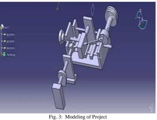
Fig. 3: Modeling of Project
Suitable manufacturing methods will be employed to fabricate the components and then assemble the test set –up
VII. IMPORTANT COMPONENTS AND DESIGN
Electric Motor
POWER= 50 WATT
OPERATING SPEED = 4000 rpm. NOW;
Belt drive between motor and pulley have a reduction ratio of 1:5 Hence Tdesign = Overload factor x 5 x Tmotor
Considering 100% overload Tdesign = 2 x 5 x .12 Tdesign = 1.2 N.m
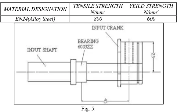
Design Of Input Crank Shaft:
MATERIAL SELECTION:- REF:-PSG DESIGN DATA (1.10&12 1.17)
MATERIAL DESIGNATION TENSILE STRENGTH N/mm2
YEILD STRENGTH N/mm2
EN24(Alloy Steel) 800 600
Fig. 5:
According to the maximum shear stress theory fsy =0.5 fyt =300N/mm2
The permissible shear stress is given by Fs all = fyt/fos
=300/2 =150 N/mm2
Section of the crank pin at is subjected to combined bending and torsional Crank force = Tdesign / eccentricity = 1.2x 10³ /25 = 48 N
Moments
Mt = 48 x 25 =1200 N-mm Mb = 48 x 45
=2160 N-mm fb = Mb y/I =2160 x 32 / d3
d = 12 mm
But as per manufacturing considerations we have an H6h7 fit between the pulley and shaft and to achieve this tolerance boring operation is to be done and minimum boring possible on the machine available is 16mm hence consider the minimum section on the shaft to be 16mm
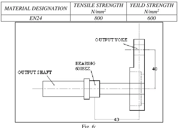
Design of Output Shaft
MATERIAL SELECTION:- REF:-PSG DESIGN DATA (1.10&12 1.17)
MATERIAL DESIGNATION TENSILE STRENGTH N/mm2
YEILD STRENGTH N/mm2
EN24 800 600
Fig. 6:
According to the maximum shear stress theory fsy =0.5 fyt =300N/mm2
The permissible shear stress is given by Fs all = fyt/fos
=300/2 =150 N/mm2
Section of the crank pin at is subjected to combined bending and torsional Crank force = Tdesign / eccentricity = 1.2x 10³ /40 = 30 N
Moments
Mt = 30 x 40=1200N-mm Mb = 30x 43
=1290 N-mm fb = Mb y/I =1290 x 32 / d3
fs =Mt r/J =1200x16/ d3
d = 10 mm
But as per manufacturing considerations we have an H6h7 fit between the dyno-brake pulley and shaft and to achieve this tolerance boring operation is to be done and minimum boring possible on the machine available is 16mm hence consider the minimum section on the shaft to be 16mm
VIII. EXPERIMENTAL ANALYSIS
Procedure
1) Position the control linkage at initial position 2) Start pump motor
3) Maintain input speed at input =100 rpm 4) Collect 100 ml of oil in measuring beaker 5) Note time for collecting 100 ml of oil 6) Change input speed to 200 rpm 7) Repeat step 4 & 5
8) Repeat procedure for 300 rpm, 400rpm and 500 rpm
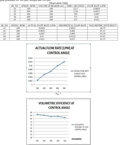
Observation Table
SR. NO. SPEED ( RPM) VOLUME IN BEAKER (ml) TIME ( SECONDS) FLOW RATE (LPM)
01 100 100 2217 0.0024
02 200 100 1130 0.0053
03 300 100 769 0.007
04 400 100 575 0.01
05 500 100 473 0.012
SR. NO. SPEED ( RPM) ACTUAL FLOW RATE (LPM) THEORETICAL FLOW RATE VOLUMETRIC EFFICIENCY
01 100 0.0024 0.0033 86.78
02 200 0.0053 0.006 85.13
03 300 0.007 0.009 83.39
04 400 0.01 0.0124 83.65
05 500 0.012 0.015 81.35
Fig. 7:
Comparative Graph Of Flow Rate Vs Speed At Various Control Angles
Fig. 9: Comparative Graph of Flow Rate Vs. Speed at Various Control Angles
IX. CONCLUSION
1) It is seen that the discharge from the pump reduces at the control angle is changed from o degree to 120 degree
2) Volumetric efficiency drops slight as the speed in all cases of control angle, this is owing to the hysteresis of spring used in the pump and friction between the piston and cylinder.
3) From the seen characteristic of flow in each control angle it can be safely assumed that the discharge of the pump increases with increase in pump speed for all control angles.
4) Precise control of the control angle will provide a wide range of flow rates therby the pump will find application in multiple industries.
Lab-View Software Analysis (Amplitude Vs Time)
REFERENCES
[1] Noah D. Manring ,Yihong Zhang mechanical and aerospace engineering department,university of missouri-columbia,columbia, 65211The “Improved
Volumetric-Efficiency of an Axial-Piston Pump Utilizing a Trapped-Volume Design” Journal of Dynamic Systems, Measurement, and Control SEPTEMBER 2001, Vol. 123 Õ 487 .
[2] Mr. Kekare H.T*, Prof. Patil S.S., Prof. Harugade N.V., Prof. Pol S.S. “Review paper on application of variable displacement linkage in radi al piston pump.” Linkage in Radial Piston pump
[3] J.M. Bergada , S. Kumar a, D.L, Davies, and J. Watton,2006 “A complete analysis of axial piston pump