A New Signal Processing based Method for
Reactive Power Measurements
Adalet Abiyev
, Member, IEEE
Girne American University/Department of Electrical and Electronics Engineering, TRNC, Turkey Email: [email protected]
Abstract—A new modified Walsh function (WF) based method for the measurement of reactive power (RP) under both sinusoidal and non-sinusoidal conditions is proposed and investigated. Proposed method simplifies the multiplication procedure to evaluate the reactive components from instantaneous power signal using peculiar properties of the WF. One of the advantages of proposed measurement approach is that in contrast to the known existing methods which involve phase shift operation of the input signal, the proposed technique does not require the time delay of the current signal to the π/2 with respect to the voltage signal. Another advantage is related to the computational saving properties of the proposed approach coming from use of the Walsh Transform (WT) based signal processing method. Proposed method eliminates an influence of the prevalent third order current harmonic to and reduces the effect of the highest order current harmonics on the RP measurement results. The examples are used to illustrate validity and effectiveness of the suggested method for evaluation of the RP. A new method has been tested by use of a simulation tools developed on the base of “Matlab”.
Index Terms—reactive power measurement, distortion power, Walsh function, current harmonics.
I. INTRODUCTION
Design and implementation of electronic RP measurement instruments is currently dictated by the strong demands to the electrical energy savings during transmission and distributions. The RP influences directly to the power factor and as a result overloads the connecting cables between the electrical energy sources and energy users and plays a vital role in the stable operation of power systems [1].
Last ten years various methods have been developed for RP measurement in both the sinusoidal and noise(in presence of harmonic distortion) conditions. Most of known research works are based on using the method of averaging the values of the product of the current signal (or samples) and the voltage signal (or samples) with shifting to the quarter one of the signals (current or voltage) relatively to another.
Reference [2] demonstrates an extension of the wavelet transform to the measurement of RP component through the use of a broad-band quadrature phase-shift networks.
This wavelet-based power metering system requires the phase shift of the input voltage signal.
In [3] the application of new frequency insensitive quadrature phase shifting method for reactive power measurements has been verified by using a time-division multiplier type wattmeter.
An electronic shifter based on stochastic signal processing for simple and cost-effective digital implementation of a reactive power and energy meter was developed in [4].
A new application of the least error squares estimation algorithm for identifying the reactive power from available samples of voltage and current waveforms in the time domain for sinusoidal and non sinusoidal signals is proposed in [5].
In [6] different RP measurement methods are described. The common drawback of the described methods is related to the necessity of measuring of the RMS values of the voltage and current.
The 2-Dimensional digital FIR filtering based algorithms for measuring of the RP are proposed in [7]. The development of a method using artificial neural networks to evaluate the instantaneous reactive power is described in [8]. In this method the back-propagation neural network is used to approximate the reactive power evaluation function.
In [9] the digital infinite impulse response filters are used to measure the reactive power. Although proposed algorithm allows evaluating the harmonic components of the RP, the suggested method is still complex because of the performing of the filtering procedures. Although the Fourier transform (FT) based digital or analogue filtering algorithms allow evaluating the RP without shifting operation, a large number of multiplication and addition operations are required for the application of the FT algorithms for RP evaluation. For example, for realization of 16 point digital Fourier transform (DFT) algorithm the 162=256 complex multiplication and the
240 15
16× = complex addition operations are required
In [11] the authors have analyzed WT algorithms employed to energy measurement process and they have shown that the Walsh method represents its intrinsic high-level accuracy due to coefficient characteristics in energy staircase representation.
Reference [12] states that decimation algorithm based on fast WT(FWT) has better performance due to the elimination of multiplication operation and low or comparable hardware complexity because of the FWT transform kernel.
In [7] the WF based RP measurement algorithm is described. The basic idea of this WF based algorithm consists in the resolving of the voltage and current signals separately along the WFs and then obtaining the RP as the difference of the products of the quadrature components. At least four multiplication-integration, two multiplication, and one summation operations required for RP evaluation makes this algorithm comparatively complex and less convenient for implementation.
In previous research work we proposed the WFs based method for RP measurement [13]. Main drawback of this method is the influence of the distortion power to the measurement results.
It was the aim of this paper to develop the algorithms for measurement of RP (i) without phase shift of π/2 between the voltage and the current waveforms, (ii) with the immunity to the distortion power, and (iii) with the relatively less computational demands. This objective was achieved by using the WF.
The paper is organized as follows. In section two a derivation of the WF based analogue signal processing algorithms for RP evaluation is described. Section three describes some realization aspects of proposed method. The simulation results and discussions are given in the section four. Section five includes the conclusion of the paper. Final section includes list of references.
II. SIGNAL PROCESSING ALGORITHMS FOR RP EVALUATION
A. Instantaneous Power in the Linear Electrical Circuits with a Sinusoidal Voltage source
As stated by IEEE standard [14], in the electrical circuit with the linear load, a sinusoidal voltage source
) sin(
2V t
v= ω
produces the sinusoidal current of
). sin(
2 ω −θ
= I t i
Where V and Iare the RMS value of the voltage and current, respectively, ω=2π/Tis the angular frequency, Tis the cycling period of v, θ is the phase angle between the voltage vand the current iwaveforms. An instantaneous power in such electrical circuit is given by [5],[6], [14]
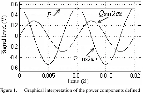
p=P−
[
Pcos2ωt+Qsin2ωt]
. (1)Figure 1. Graphical interpretation of the power components defined by (1): ω=2π/T,T=1/f ,
Hz
f =50 ,v=2.4sinωt,i=0.5sin(ωt−0.5). WhereP=VIcosθ and Q=VIsinθare the active and reactive power, respectively.
Time representation of the right side terms of (1), which comprises both the constant and the cycling portions of instantaneous power, is shown in Fig.1.
B. The Analytical Expression and Graphical Representation of the Walsh Functions
Being full orthogonal system the WF has interesting peculiarities, one of which is that it has only two values (+1 or -1) over the specified normalized time period. This specificity of WF greatly increases an effectiveness of signal processing operations related to the measurement of the parameters and characteristics of ac signals. Particular advantages of WF appear on its application in RP measurement discussed further in this paper.
Analytically the WF can be expressed as follows [13]:
( ) ( )
∑
= − + ⊕ − ⎟
⎟ ⎟ ⎠ ⎞ ⎜
⎜ ⎜ ⎝ ⎛
− =
m
k m k k
l k m l
l
Wal 1
1
1 ,
β
β
, (2)wherelis order of WF in the WF system, l =0,1,2,…,N-1, lm is the
th
m bit(digit) coefficients of the l
represented in binary code: l=
(
l0,l1,l2,...,lm)
2, lm =0,1. m is the highest-order WF serial number in the WF system,β is argument of WF and defines the bit(digit) coefficients of βk represented in binary code,
(
1, 2...)
2, =0,1= β β βk βk
β and k=1,2,...,m.
The argument, βk changes depending on normalized
time of T=0.02sec. as shown in the Fig.2.
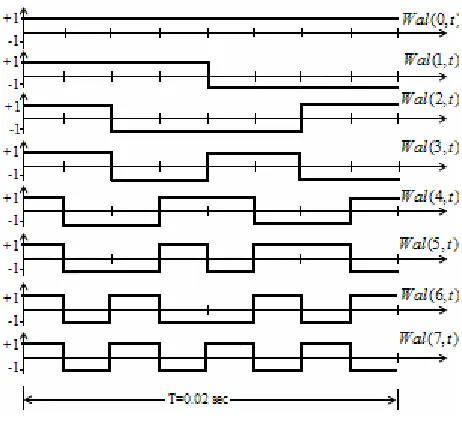
Graphical representation of first eight WFs drawn by
use of (2) is shown in Fig.3.
Example below illustrates the procedure of graphical representation of zero-and third-order WFs by use of the
mathematical expression of (2).
Example
Figure 2. Time representation of final three bit coefficients of
k
β .
For zero order WF l =0 or l=
(
0,0,0,...,0)
2. From (2) we have( ) ( )
∑ = − + ⊕ − ⎟⎟⎟ ⎟ ⎟ ⎟ ⎠ ⎞ ⎜⎜ ⎜ ⎜ ⎜ ⎜ ⎝ ⎛ − = 3 1 1 1 , 0 k k k m i k m i Wal β β=
( )
1 3 2 1 2 1 2 1 0 3 β β β ⎟⎟ ⎟ ⎟ ⎟ ⎟ ⎠ ⎞ ⎜⎜ ⎜ ⎜ ⎜ ⎜ ⎝ ⎛ ⎟⎟ ⎟ ⎟ ⎟ ⎟ ⎠ ⎞ ⎜⎜ ⎜ ⎜ ⎜ ⎜ ⎝ ⎛ ⎟⎟ ⎟ ⎟ ⎟ ⎟ ⎠ ⎞ ⎜⎜ ⎜ ⎜ ⎜ ⎜ ⎝ ⎛ ⊕ + ⊕ + ⊕ − i i i i i iSince all bit coefficients of i=
(
i0,i1,i2,...,im)
2 for zero order WF equal to zero, the last expression is rewritten as( ) ( )
0, 1 3 ( 1)0 10 2 0 1 0 = − = − = ⎟⎟ ⎟ ⎠ ⎞ ⎜⎜ ⎜ ⎝ ⎛ ⎟⎟ ⎟ ⎠ ⎞ ⎜⎜ ⎜ ⎝ ⎛ ⎟⎟ ⎟ ⎠ ⎞ ⎜⎜ ⎜ ⎝ ⎛ β+ β + β β Wal
Thus zero order WF equal to +1 over the full normalized time period of T(See Fig.3).
Since the RP measurement is related to the third order WF, we find the time representation of third order WF by using the expression (2).
( ) ( )
∑ = − + ⊕ − ⎟⎟⎟ ⎟ ⎟ ⎟ ⎠ ⎞ ⎜⎜ ⎜ ⎜ ⎜ ⎜ ⎝ ⎛ − = 3 1 1 1 , 3 k k k m i k m i Wal β βFor the third-order Walsh function WF l=3 or in binary representation l=
(
0011)
2. So,1 , 1 , 0 ,
0 1 2 3
0 = l = l = l =
l . Considering these bit
coefficients the third order WF simplifies to
( ) ( )
22 ) 1 ( 1 , 3 3 0 0 0 1 1 1 1 β β β β β = − = − ⎟⎟ ⎟ ⎠ ⎞ ⎜⎜ ⎜ ⎝ ⎛ ⎟⎟ ⎟ ⎠ ⎞ ⎜⎜ ⎜ ⎝ ⎛ ⎟⎟ ⎟ ⎠ ⎞ ⎜⎜ ⎜ ⎝ ⎛⊕ + ⊕ + ⊕ i Wal
The WF argumentβ2, which is shown in Fig.2, is the
function of time varying as follows
⎩ ⎨ ⎧ ≤ ≤ ≤ ≤ ≤ ≤ ≤ ≤ = T. t 3T/4 and 2 / 4 / for ; 1 ; 4 / 3 2 / and 4 / 0 for ; 0 2 T t T T t T T t β
As a result, the third-order WF changes over the normalized time of T as follows
Figure 3. Time representation of the first eight WFs with the normalized period of 0.02 sec.
⎩ ⎨ ⎧ ≤ ≤ ≤ ≤ − ≤ ≤ ≤ ≤ + = T. t 3T/4 and 2 / 4 / for ; 1 ; 4 / 3 2 / and 4 / 0 for ; 1 ) , 3 ( T t T T t T T t Wal β
Timing diagram of Wal
( )
3,β
is shown in the Fig.3.C. A New Algorithm for Measuring of the RP in the Linear Electrical Circuit with a Sinusoidal Voltage source
Multiplication of both sides of (1) by the 3rd order WF
) , 3 ( t
Wal results in
) , 3 ( 2 sin ) , 3 ( 2 cos ) , 3 ( ) , 3
( t PWal t P tWal t Q tWal t
pWal = − ω − ω .
As can be seen from Fig.3, the 3rd order WF, )
, 3 ( t
Wal with the normalized period ofT oscillates with the similar frequency of the RP component, Qsin2ωt of instantaneous power p (Fig.1). Thus an integral taken from the both sides of last equation over the timeT is given by[15]
∫
=−∫
T T dt t Q T dt t pWalT 0 0 sin(2 )
1 ) , 3 ( 1 ω (3)
Solution of (3) for the reactive power Qresults in an algorithm for the RP measurement:
D. A New Algorithm for Measuring of the RP under Noise Conditions
The dominant harmonic frequencies produced by the most of the industrial loads are the odd integer multiples of the fundamental frequency. Among the odd harmonics the third harmonic is the most prevalent. Therefore in this section an attention is concentrated mainly on the third order harmonic.
Assume that the voltage signal is sinusoidal and the load current is contaminated with the third order current harmonic, i.e. i3 =Im3sin(3ω −t φ3). In this case the instantaneous power p is given by[5]
. 4 sin 4
cos
2 sin ) ( 2 cos ) (
3 3
3 3
t Q
t P
t Q Q t P
P P p
d d
d d
ω ω
ω ω
−
− −
+ −
+ =
(5)
WhereIm3is the peak value of the third order current
harmonic, φ3is the phase angle between the fundamental
voltage and the third order current harmonic waveforms, Pd3 =UI3cosφ3; Qd3=UI3sinφ3. (6) WhereI3 is the RMS value of the third order current harmonic.
To derive the RP measurement algorithm we multiply the (5) to the third order WF, Wal(3,t)and then take integral over the timeT:
∫
[
]
=∫
−[
]
T
d T
dt t Wal t Q Q T dt t Wal p
T0 0( 3 )sin2 (3,)
1 ) , 3 (
1 ω
(7)
As the integrals of the right hand side terms of (5) that involve the multipliers ofcos2ωt,cos4ωt, sin4ωt, and the constant Pare equal to zero, the right side of (7) does not include these integral terms.
Since the product of the third order WF by the
t Q Qd )sin2ω
( 3− results in the full-wave rectification of
t Q Qd )sin2ω
( 3− term, (7) is rewritten as follows [15]
∫
[
]
=∫
− Td T
dt t Q Q T dt t Wal p
T0 0( 3 )sin2
1 ) , 3 (
1 ω
. (8) Solution of this equation for the Qresults in
[
]
3 0) , 3 (
2 d
T
Q dt t Wal p T
Q=−π
∫
+ . (9)The reactive component of the distortion power, Qd3on
the right side of (9) represents an influence of the third order current harmonic, i3to the RP measurement
algorithm (4).
The final term of the right side of (5) is the distortion power term of Qd3sin4ωtoscillating with the frequency of 4ω(Fig.4,curve2). This frequency is similar to the oscillating frequency of the 7thorder WF,
) , 7 ( t
Wal shown in the Fig.4(curve1).
Figure 4. Timing diagrams: 1-Wal(7,t); 2-Qd3sin4ωt; 3-product of the MWF, Wal(7,t) by the Qd3sin4ωt, i.e.
) 4 sin ))( , 7 (
(Wal t Qd3 ωt .
To estimate the distortion power term Qd3sin4ωtwe multiply the both sides of (5) to the 7thorder WF
) , 7 ( t
Wal and then take integral over the timeT:
∫
[
]
=−∫
[
]
T
d T
dt t Wal t Q T dt t Wal p
T0 0 3sin4 (7,)
1 ) , 7 (
1 ω
. (10) Since the integral terms of the right hand side of (5) that involve the products of Wal(7,t)⋅cos2ωt,
t t
Wal(7, )⋅cos4ω , Wal(7,t)⋅sin2ωt, and the
P t
Wal(7, )⋅ are equal to zero, the right side of (10) does not contain mentioned integral terms.
As the 7thorder WF Wal(7,t)shown in the Fig.4(curve1), is the odd function with the frequency similar to the frequency of Qd3sin4ωt term, the product of the 7thorder WF by the Qd3sin4ωt results in the rectification of the Qd3sin4ωt(Fig.4, curve 3). Taking into account this rectifying effect (10) is rewritten as follows
∫
[
]
=−∫
Td T
dt t Q T dt t Wal p
T0 0 3sin4
1 ) , 7 (
1 ω
. (11) Solution of (11) for Qd3 results in
=−
∫
[
]
Td pWal t dt
T Q
0
3 (7,)
2
π
. (12) Substitution of (12) into (9) results in a new algorithm for the measuring of RP under noisy conditions:
[
]
[
]
⎪⎭ ⎪ ⎬ ⎫ ⎪⎩
⎪ ⎨ ⎧
+ −
=
∫
∫
T T
dt t Wal p dt t Wal p T Q
0 0
) , 7 ( )
, 3 ( 2
π
(13)
current harmonics is also essentially reduced when (13) is used as the RP measurement algorithm.
E. Modified WF based Algorithm for Measuring of RP in Noise Conditions
Realization of proposed algorithm (13) requires the generation of two Walsh functions, two multiplication and integration operations that make it less convenient for the implementation.
To avoid this disadvantage we sum the 3rdand the
th
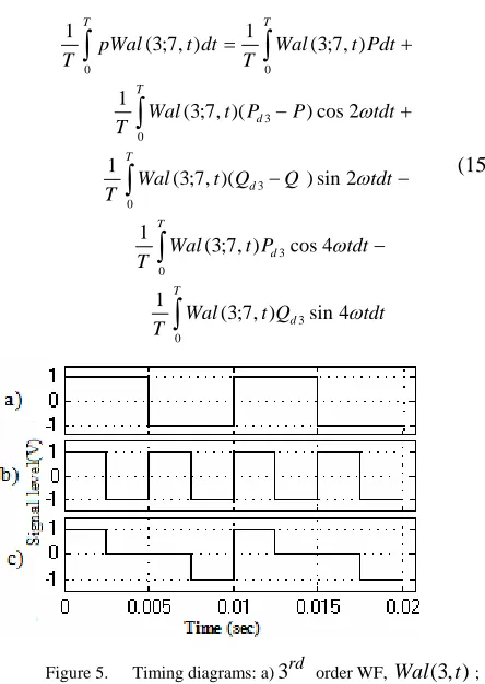
7 order Walsh functions[15]. Time diagrams of these functions are shown in the Fig.5a and Fig.5b, respectively. Algebraic sum of these functions called as the modified WF(MWF), shown in Fig.5c., can be expressed as follows
[
(3, ) (7, )]
2 1 ) , 7 ; 3( t Wal t Wal t
Wal = + . (14)
Close inspection of Fig.5 shows that the MWF, synthesized from the standard 3rdand the 7 order th Walsh functions, is defined as follows
⎪⎩ ⎪ ⎨ ⎧+ = T] [7T/8; , ] 2 / ; 8 / 3 [ interv. in is if 1 -] [5T/8;7T/8 , ] 8 / 3 ; 8 / [ interv. in is if 0 [T/2;5T/8] , ] 8 / ; 0 [ interv. in is if 1 ) , 7 ; 3 ( T T t T T t T t t Wal
Now for deriving of RP measurement algorithm by use of the MWF we multiply the both sides of (5) by the MWF, Wal(3;7,t)and take integral over the timeT[15]:
∫
∫
∫
∫
∫
∫
− − − + − + = T d T d T d T d T T tdt Q t Wal T tdt P t Wal T tdt Q Q t Wal T tdt P P t Wal T Pdt t Wal T dt t pWal T 0 3 0 3 0 3 0 3 0 0 4 sin ) , 7 ; 3 ( 1 4 cos ) , 7 ; 3 ( 1 2 sin ) )( , 7 ; 3 ( 1 2 cos ) )( , 7 ; 3 ( 1 ) , 7 ; 3 ( 1 ) , 7 ; 3 ( 1 ω ω ω ω (15)Figure 5. Timing diagrams: a)3rd order WF, Wal(3,t); b)7th order WF, Wal(7,t); c) Synthesized WF, Wal(3:7,t).
The first integral on the right side of (15) equal to the zero becausePis constant and MWF is periodic function. Second and fourth integrals on the right side of (15) are also equal to the zero because these terms include the cosine function that is orthogonal with the MWF. Since the third as well as the fifth integrals comprise the product of the MWF by the sine functions resulting in the rectification of both the (Qd3−Q )sin2ωtand the
t
Qd3sin4ω waveforms, these integrals are not equal to
zero. The third integral of the right side of (15) is determined as π ω ( ) 2 sin ) )( , 7 ; 3 ( 1 3 0 3 Q Q tdt Q Q t Wal T d T d − = −
∫
. (16)Solution of fifth integral of the right side of (15) results in π ω ω 3 8 / 0 3 0
3 sin4
4 4 sin ) , 7 ; 3 (
1T d T d
d Q tdt T Q tdt Q t Wal
T
∫
=∫
= . (17)Substituting (16) and (17) into (15) we obtain a new algorithm for measuring of RP in sinusoidal and noise conditions as follows
=−
∫
T dt t pWal T Q 0 ) , 7 ; 3 ( π. (18)
Advantage of this algorithm is that it requires one MWF for measuring of the RP in noise condition.
III. SOME REALIZATION ASPECTS OF DEVELOPED RP MEASUREMENT ALGORITHM
This section describes a realization of WF based RP metering algorithm[16]. Its block diagram is shown in the Fig.6. The voltage and current signals are fed to the inputs of the analog multiplier(AD633), which produces time continuous output proportional to the instantaneous powerp defined by (1).. The output of AD633 is fed to the analog-to- digital converter(ADC0804) controlled by the control logic(CL). To achieve the frequency insensitive measurement the digital sampler(DS) generates sampling signals from input voltage v.
The ADC0804 converts the input signal p to the digital output p(n). The output from the ADC0804 is fed to the inputs of the up-down counter(UDC) through the multiplexer. The multiplexer is used to connect the output of the ADC0804 to either the up input or the down input of the UDC in accordance with the WF based RP measurement algorithm. Thus first and third quarter parts of the p(n) are entered to the “UP” input and the second and forth quarter parts of p(n) are entered to the “DOWN” input of the UDC. So the remainder number in the UDC to the end of the second period of the input signal becomes equal to the RP of the investigated circuit. The display indicates the binary output of UDC.
The important component of the electronic RP meter providing the independence of the measurement results from the input signal frequency variation is the DS(Fig.7). DS produces sampling signals with the frequency correlated with the input signal frequency.
A zero crossing detector(Fig.7) produces the pulses with the cycling period proportional to the period T of the input voltage signal v. During first, so-called preparation period T the CL enables the output impulses of the clock to be passed through the binary ripple counter(BRC) only to the input of the binary storage counter (BSC). The counter capacity N of the BRC is defined in accordance with the Shannon criterion of sampling rate of the instantaneous power signalp.
m
N =2 , mis the number of bits of BRC. The number of impulses stored in the BSC to the end of preparation time lengthT , is given by[16]
M=(fcT)/N. (19)
Where, fcis the clock frequency.
Starting at the beginning of the second period Tthe CL enables the output impulses of the clock to be passed only to the input of the binary counter(BC). The code comparator(CC) compares the parallel outputs of the BSC to the BC outputs. When the number of the clock impulses countered by BC becomes equal toM, the CC produces output impulse. This impulse sets the BC to zero and becomes the first output sampling signal of DS. The clock pulses continue to enter to the input of BC continuously over the second full period of T. When the number of impulses counted by the BC again becomes
Figure 7. Digital sampler.
equal to the M, the CC produces the second output impulse of the DS setting the BC to zero and so forth. The time interval Tsbetween the neighboring output impulses of the DS is given by
Ts =M/ fc. (20) Where Ts is the sampling interval and fs=1/Ts is the
sampling frequency. Substitution (19) into (20) results in expression relating sampling interval Tsto the input
power frequency signal periodT :
Ts =T/N. (21)
So repetition interval Ts of the DS output impulses is
Ntimes less theT . This relationship can also be written in terms of input and output frequencies as follows
fs =N⋅f . (22)
Where f =1/Tis the input signal frequency.
Thus, sampling period Tsbecomes the function of the
periodT of the input signalp being sampled.
Carefully look at the derived expressions of (21) and (22) allows to state that designed electronic power meter meets the requirement of coherent data acquisition and thereby is the good solution for the preventing the energy leaking from spectral components when input signal frequency f varies because of the power distribution system instability[16]. Proposed approach to implementation of the DS can find wide application where immunity to the input signal frequency variation is of prime concern.
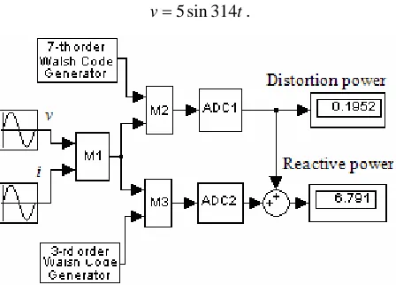
IV. SIMULATION RESULTS AND DISCUSSIONS A simulation circuit of the reactive and distortion power measurement instrument based on the algorithm of (13) has been built(Fig.8). The simulation experiments have been performed in two steps. During first step the input voltage v was taken as pure sinusoidal signal given by
t v=5sin314 .
Figure 8. Simulation structure for the reactive and distortion power measurement algorithm: M1, M2, M3-analog multipliers; ADC1,
TABLE I. THE SIMULATION RESULTS OF THE RPEVALUATION
ALGORITHMS
The current signal iwas contaminated with third order current harmonic: i=3sin(314t−ϕ)+1sin(942t−0.35).
The phase angle ϕ between the fundamental voltage and current waveforms has been varied in the interval of
° − =0 90
ϕ to provide the full scale variation for the reactive power. The simulation results are presented on the Table I. The true values of RP(second column of Table I) for the different phase angles have been calculated by use of the classical algorithm of
ϕ
sin
UI
Q= .
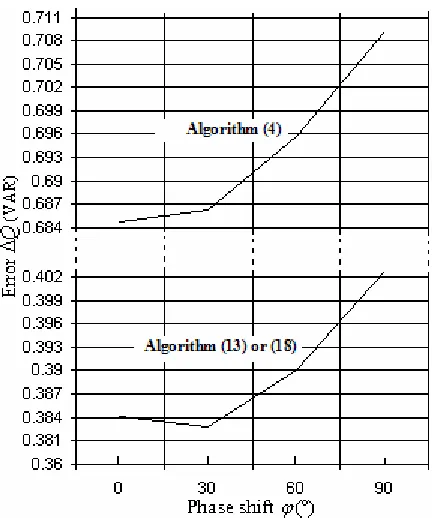
Effect of the harmonics on the RP measurement, when (4) is used as measurement algorithm, is clearly seen from the Table I and the Fig.9. The error, introduced by harmonics, against the RP variation through the phase shift ϕis plotted in the Fig.9.
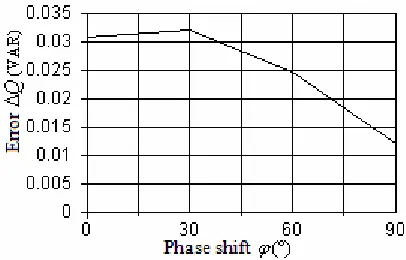
Elimination of an effect of third order harmonic on the measurement results by use of the algorithms (13) or (18) is explicitly seen from the Table I and Fig.10 (e.g. error introduced by the third order current harmonic is reduced from 0.84232 VAR to the 0.0321 VAR).
Proposed algorithms (13) and (18) have also property of reducing the effect of the highest order odd current harmonics on the measurement accuracy. To verify this property the current signal, applied to the input of the simulation structure of Fig.8, was contaminated with all odd harmonics starting from 1st up to11th:
) 75 . 0 3454 sin( 27 . 0 ) 5 . 1 2826 sin( 33 . 0
) 45 . 0 2198 sin( 43 . 0 ) 5 . 0 1570 sin( 6 . 0
) 35 . 0 942 sin( ) 314 sin( 3
− +
−
+ −
+ −
+ −
+ − =
t t
t t
t t
i
ϕ
Figure 9. Error caused by the third order current harmonic when (4) is used as the reactive power measurement algorithm.
Figure 10. Error caused by the third order current harmonic when (18) is used as the reactive power measurement algorithm.
The measurement data(readings) obtained from simulation tool of Fig.8 and the error introduced by the current harmonics are represented in the Table II. The property of the proposed algorithms (13) and (18), reducing the influence of the highest order odd current harmonics on the measurement accuracy, is seen from Fig.11. Inspection of Fig.11 shows that use of either the (13) or the (18) as the reactive power measurement algorithm reduces the error caused by the odd current harmonics approximately 1.75 times.
The proposed RP measurement method based on the algorithms (13) and (18) does not require a phase shift of the current signal to the π/2with respect to the voltage signal. The phase shift operation requires the corresponding hardwire which may result in the additional measurement error [3].
V. CONCLUSION
A new modified WF based method for the measurement of RP in sinusoidal as well as in noise conditions has been proposed and investigated. Evaluation of RP using proposed WF based algorithms results in certain advantages:
a)The requirement of IEEE/IEC definition of a phase shift of π/2 between the voltage and the current signals, typical for reactive power evaluation, is eliminated from signal processing operation. RP is evaluated without the phase-shift operation to achieve increased efficiency of computational operations and hardware implementation.
TABLE II. THE SIMULATION RESULTS IN CASE OF MULTIHARMONIC CURRENT SIGNAL
Algorithm (4) Algorithms (13), (18) True
value Reading Error Reading Error )
(°
ϕ
Q Q ∆Q Q ∆Q
0 0.000 -0.84075 0.84075 -0.03068 0.03068 30 -3.748 -2.90568 0.84232 -3.78010 0.03210 60 -6.493 -5.6411 0.8519 -6.51772 0.02472 90 -7.500 -6.6345 0.8655 -7.51201 0.01201
Algorithm (4) Algorithms (13), (18) True value Reading Error Reading Error )
(°
ϕ
Q Q ∆Q Q ∆Q
Figure 11. Error caused by the odd current harmonics including
st
1 up to11th.
b)Proposed algorithms (13) and (18) eliminate an influence of the prevalent third order current harmonic completely from, and reduce the influence of the highest order odd current harmonics approximately 1.75 times on the RP measurement results.
c)Proposed algorithm (12) allows estimating of the current distortion power caused by the third order current harmonic.
REFERENCES
[1] Fairney, W. “Reactive power-real or imaginary? ”, Power Engineering Journal,Volume 8, Issue 2, April 1994, pp.69 – 75.
[2] W.-K. Yoon and M.J. Devaney. “Reactive Power Measurement Usinq the Wavelet Transform”, IEEE Trans. Instrum. Meas.,vol. 49, pp 246-252, April 2000. [3] Branislav Djokic, Eddy So, and Petar Bosnjakovic. “A
High Performance Frequency Insensitive Quadrature Phase Shifter and Its Application in Reactive Power Measurements” IEEE Trans. Instrum. Meas.,vol. 49, pp 161-165, February 2000.
[4] S.L.Toral, J.M.Quero and L.G.Franquelo. “Reactive power and energy measurement in the frequency domain using random pulse arithmetic”, IEE Proc.-Sci. Technol., vol. 148, No. 2, pp.63-67, March 2001.
[5] Soliman S.A., Alammari R.A., El-Hawary M.E., Mostafa M.A. “Effects of harmonic distortion on the active and reactive power measurements in the time domain: a single phase system” Power Tech Proceedings, 2001 IEEE Porto, Volume 1, 10-13 Sept. 2001, 6 pp.
[6] Munday M., Hart D.G. “Methods for electric power measurements”, IEEE Power Engineering Society Summer Meeting, , Vol.3, pp 1682 -1685, July 2002.
[7] M. Kezunovic, E. Soljanin, B. Perunicic, S. Levi, “ New approach to the design of digital algorithms for electric
power measurements”, IEEE Trans. on Power Delivery, vol. 6, No 2, pp. 516–523,Apr. 1991.
[8] T.W.S.Chow and Y.F.Yam. “Measurement and evaluation of instantaneous reactive power using neural networks”, IEEE Trans. on Power Delivery, Vol. 9, No. 3, July 1994, pp.1253-1260.
[9] A. Ozdemir and A. Ferikoglu. “ Low cost mixed-signal microcontroller based power measurement technique”, IEE Proc.-Sci. Meas. Technol., Vol. 151, No. 4, July 2004,pp.253-258.
[10]Emmanuel C. Ifeachor, Barrie W. Jervis. Digital Signal Processing. A practical Approach. Second Edition. Prentice Hall, 2002.
[11]Brandolini A., Gandelli A., Veroni F. “Energy meter testing based on Walsh transform algorithms”, Instrumentation and Measurement Technology Conference, 1994. Conference proceedings, 10-12 May 1994, pp 1317 – 1320, vol.3.
[12]Bai liyun, Wen biyang, Shen wei, and Wan xianrong. “Sample rate conversion using Walsh-transform for radar receiver”, Microwave Conference Proceedings, APMC 200, Vol. 1, 4-7 Dec. 2005, 4 pp.
[13]Abiyev R. H., Abiyev A. N., Kamil D. “The Walsh Functions Based Method for Reactive Power Measurement”, in Proceedings of the 33rd Annual Conference of the IEEE Industrial Electronics Society (IECON'07), Taipei, Taiwan, Nov. 5-8, 2007, pp. 2337-2342.
[14]IEEE Std. 1459-2000, “IEEE Trial Use Standard Definitions for the Measurement of Electric Power Quantities Under Sinusoidal, Non-Sinusoidal, Balanced, or Unbalanced Conditions”, Institute of Electrical and Electronics Engineers / 01-May-2000 / 52 pages.
[15]Adalet N. Abiyev, “A new signal processing technique for evaluation of the reactive power in the power transmission and distribution systems”, in
Proceeding of Southeastcon 2008,IEEE, Hantsville, AL, USA., April 3-6, 2008, pp. 356-361.
[16]Adalet N Abiyev, “A new electronic reactive power meter based on Walsh Transform algorithms”, in Proceeding of IEEE Transmission and Distribution Conference and Exposition, 2008 (T&D. IEEE/PES), Chicago, IL, USA, April 21-24, 2008, pp. 1-7.
Adalet Abiyev was born in Azerbaijan, in 1952. Received Electrical Engineer degree and Ph.D degree in Electrical and Electronic Engineering in 1975 and 1986, respectively, both from the Azerbaijan State Oil Academy(ASOA).
From 1986 to 1990 he was assistant professor and then from 1991 to 2005- associate professor at the department of “Automatics, Remote Control and Electronic” of ASOA. From 2006-present he is working as associate professor at the department of Electrical and Electronic Engineering of the Girne American University. His research interests are electronic power measurements, analogue and digital signal processing, testing and diagnosing of induction motors during mass production.