Medical Devices: Evidence and Research
Dove
press
O R i g i n A L R E s E A R C h
open access to scientific and medical research
Open Access Full Text Article
Preliminary development of the Active
Colonoscopy Training Model
Junghun Choi1
Kale Ravindra1
Randolph Robert1
David Drozek2
1Mechanical Engineering, Ohio
University, Athens, Oh, UsA; 2College
of Osteopathic Medicine, Ohio University, Athens, Oh, UsA
Correspondence: Junghun Choi 254 stocker Center, Mechanical Engineering, Ohio University, Athens, Oh 45701, UsA
Tel +1 740 593 2739 Fax +1 740 593 0476 Email choij1@ohio.edu
Abstract: Formal colonoscopy training requires a significant amount of time and effort. In particular, it requires actual patients for a realistic learning experience. The quality of colonos-copy training varies, and includes didactic courses and procedures proctored by skilled surgeons. A colonoscopy training model is occasionally used as part of the training method, but the effects are minute due to both the simple and tedious training procedures. To enhance the educational effect of the colonoscopy training model, the Active Colonoscopy Training Model (ACTM) has been developed. ACTM is an interactive colonoscopy training device which can create the environment of a real colonoscopy procedure as closely as possible. It comprises a configurable rubber colon, a human torso, sensors, a display, and the control part. The ACTM provides audio and visual interaction to the trainee by monitoring important factors, such as forces caused by the distal tip and the shaft of the colonoscope and the pressure to open up the lumen and the localization of the distal tip. On the computer screen, the trainee can easily monitor the status of the colonoscopy, which includes the localization of the distal tip, maximum forces, pressure inside the colon, and surgery time. The forces between the rubber colon and the constraints inside the ACTM are measured and the real time display shows the results to the trainee. The pressure sensors will check the pressure at different parts of the colon. The real-time localized distal tip gives the colonoscopy trainee easier and more confident operation without introducing an additional device in the colonoscope. With the current need for colonoscopists and physicians, the ACTM can play an essential role resolving the problems of the current colonoscopy training model, and significantly improve the training quality of the colonoscopy.
Keywords: colonoscope, Colonoscopy Training Model, force, pressure measurement, localization
Introduction
Colorectal cancer, also known as colon cancer, is a type of cancer in which there is cancerous growth in the colon, rectum, and appendix. It is the fourth most com-monly observed form of cancer. Approximately 70% to 80% of colorectal cancers occur among people at average risk, which is defined as any individual who is not categorized as being at risk. Consequently, a total colonoscopy is suggested once every 10 years for all people above 50 years of age.1 Colonoscopy – an endoscopic examination of the colon and the end part of the small bowel – is an important medi-cal procedure in diagnosing colorectal disorders. Medimedi-cal professionals need to have sufficient training practice to gain expertise. In the US, the American Society for Gastrointestinal Endoscopy (ASGE) suggests that a minimum 100 colonoscopies be performed by medical students to acquire proficiency, and most are thought to require
Medical Devices: Evidence and Research downloaded from https://www.dovepress.com/ by 118.70.13.36 on 24-Aug-2020
For personal use only.
Number of times this article has been viewed
This article was published in the following Dove Press journal: Medical Devices: Evidence and Research
Dovepress
Choi et al
more than this number.2 When medical students are trained, this training is usually complicated and associated with long procedure times, causing discomfort to patients. During the last 20 years, a number of simulators have been developed in order to enable the students to practice in a controlled and safe environment.3 Modifications in medical practice which constrains the education time, patient availability, and also increasing medical knowledge in this field, have led to large scale use of simulators in training and education for medi-cal students. It is predicted that with further technologimedi-cal advancements, practice on simulators will become a requisite before operating on humans.4
Currently, colonoscopy training models can be cat-egorized visually, based on virtual reality, visual part with feedback mechanism, and an ex vivo simulator using part of an animal or mechanical model. Sedlack et al developed an ex vivo bovine colon model to evaluate colonoscopy skill assessment, which comprised an ex vivo bovine colon with a model platform.5 The hard cover prevents the trainee from obtaining visual information about the procedure. The trainee can acquire information on the colonoscopy proce-dure by reaching specific landmarks in the bovine colon.5 The main function of the model was to improve intubation skill, and no multiple parameters such as the critical forces and pressure inside the colon could be observed, and the local-ization was manually accomplished. Felsher et al evaluated the GI Mentor (Simbionix, Lod, Israel) flexible endoscopy simulator and checked the significance of the performances between beginners and experts. The GI Mentor is a kind of virtual reality simulator with various scenarios. More research is needed to determine the qualification training and certifying courses for trainees.6 Grantcharov et al assessed gastrointestinal endoscopy skills using a virtual reality simu-lator (GI Mentor II computer system). Three groups were included in the study on experiences with GI endoscopy. For the identical test instruction on the simulator, significant differences in performances were found in the three groups, and GI Mentor can be used for training and assessment.7 The GI Mentor series comprises very expensive equipment and not all the test assessments were satisfied by the users. Tsang et al conducted the literature search through Medline using the key words: ‘virtual reality simulation in vascular surgery’, ‘virtual reality simulation in surgery’, ‘vascular surgery training’, ‘endovascular training’, and ‘credential-ing vascular surgeons’. Two main positive conclusions were drawn: virtual reality simulation can improve the trainee’s skill and the quality of performances and virtual reality can be used to enhance the current training quality which
can enhance patient safety.8 Haycock et al investigated the validation of the Olympus colonoscopy simulator as an effec-tive training platform to develop colonoscopy skills. Trainees were divided into 2 groups: simulator training and patient-based training groups. The general performances of novices were improved after the novice trainees trained using the colonoscopy training model, although the simulator could not provide interaction with patients or a real environment.9 Mahmood and Darzi studied the effect of the HT Immersion Medical Colonoscopy Simulator (HT IMCS) to improve clinical performance. Three different groups (experienced, intermediate, and novice) performed randomly Module 3 or 4 of the HT IMCS to compare the ability to overcome looping problems. The results indicated that the experienced group outperformed the intermediate group and the intermediate group performed better than the novice group. HT IMCS technology differentiated the skills of trainees and can be used as a performance indicator or training tool.10 Most of the ex vivo models comprise an artificial colon, abdomen body, abdomen cover, and variable colon fixture sets. Inside, the rubber or silicon colon features shapes similar to the different parts of the real colon. The feeling of insertion or operation with a colonoscope is claimed to be similar to that with a human patient. The manually configurable colon fixture enables the trainee to adjust the difficulty of the colonoscopy. A real animal model is not available for colonoscopy due to the inadequate resemblance of the human colon. For the efficiency of the colonoscopy simulators, Kim et al showed that not all the simulators are efficient in improving the colonoscopy. Generally, the colonoscopy simulators are based on the graphics on the screen or virtual reality and have been developed to enhance the effect of colonoscopy training. After using the Simbionix GI Mentor II endoscopy simulator, the only distinguished parameter which determines the skill level was surgery time for each part of the colon and the overall realistic simulation of human endoscopy was deficient in substituting human subjects.11 Computer simulation itself is not helpful in enhancing the training effect. Mahmood and Darzi suggested that the feed-back of the colonoscopy simulator was vital to increasing the efficiency of the training. Some colonoscopy simulators did not have an artificial colon part, and electrical motors with encoders generate feedback effects with respect to the scene on the screen.12 Realistic feedback to the shaft of the colonoscope is one of the keys to validating the learning curve for the HT IMCS.12–14
Most of the colonoscopy simulators measured partial outcomes such as intubation skills (ability to reach the cecum,
Medical Devices: Evidence and Research downloaded from https://www.dovepress.com/ by 118.70.13.36 on 24-Aug-2020
Dovepress Developing the Active Colonoscopy Training Model
or escape the loop problem), differentiation of trainee (novice/ intermediate/expert). A low cost ex vivo simulator cannot provide the comprehensive assessments and even high cost training models demonstrated a lack of reality including interaction with patients and the surgery-like environment. The output assessments were divided into excellent, good, and mediocre. The development of a low cost colonoscopy training model which can stably offer broad-spectrum assess-ments with a real patient present environment is needed, to enhance the colonoscopy training quality effectively.
Methods
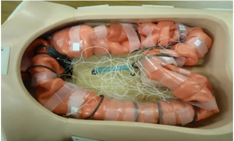
Figure 1 shows the ACTM, a conventional colonoscopy train-ing model was used as the base of the ACTM. Ten load cells were attached at the interface between the black rubber rings and the artificial colon. The load cell drivers were connected to the load cells and the analog digital converters in the data acquisition system. Twenty-four photo sensors were also connected to the digital ports of the data acquisition system through the sensor drivers. One pressure transducer was installed at the cecum to monitor pressure inside the colon. The data acquisition system was connected to the computer through a USB port to transfer all the information from the sensors. The monitor displays the real-time information and summarizes the performance of the colonoscopy for each trainee after the colonoscopy procedure is completed.
Force measurements
There are 2 different types of forces from the colonoscope to the colon: quasi-static and dynamic force. The quasi-static force from the colonoscope results mainly from the stiffness of the colonoscope shaft. It can be exerted without an advanc-ing or retractadvanc-ing motion. The colonoscope shaft comprises a
rubber cover, stainless steel braces, and interior components, such as channels for water, air, biopsy forceps, fiber optic lines. Such components mean that a colonoscope exerts a quasi-static force inside the colon when the colonoscope shaft has a curvature in the colon. Normally, the smallest radius of curvature exists at the sigmoid colon (except for splenic and hepatic fractures) and the attachment of the general sigmoid mesocolon has a U or V shape.16,17 The radius of curvature of the colonoscope shaft is much bigger than that because of its stiffness.18 Except for certain occasions, the quasi-static force is negligible compared with the dynamic force.
Dynamic forces from the distal tip or the shaft of the colonoscope are the main sources of trauma to the colon especially during looping.19,20 For the distal tip, the colonos-copist can feel the lateral force by manipulating the dial knobs at the base of the colonoscope (it occasionally occurs near the cecum) to achieve a 180-degree view. The possibil-ity of mechanical trauma is relatively low as a result of the lateral motion of the distal tip. The axial force at the end of the distal tip can be more severe and result in perforation when the colonoscopist pushes the shaft of the colonoscope to advance the distal tip. The colonoscopist must carefully advance the shaft and manipulate the distal tip to avoid severe contact between the end of the distal tip and mucosa. Another mechanical trauma can occur at the lower part of the colon, caused by the shaft of the colonoscope. Generally, the beginning of the sigmoid colon has the first sharp radius of curvature and the region keeps stressed throughout the entire advancing process of the colonoscopy.
Figure 2 shows the low profile load cells with drivers used to measure the forces from the colonoscope. Owing to the nature of the forces, only tensions were considered. Ten load cells were installed inside the colonoscopy training model, and there are 3 different ranges of force measurement capabilities for the different locations. The lower portion of the colon will take more force than the other parts of the colon due to the small number of radii of curvature. The first 5 load cells which
Figure 1 The top view of the Active Colonoscopy Training Model.15 The base is the conventional colonoscopy training model with an artificial ex vivo colon, and 10 low profile load cells, 24 light sensors, and pressure transducers are integrated with the drivers and the data acquisition system.
Figure 2 The low profile load cell (4 wire full bridge) with the driver (left) and the load cells installed in the Colonoscopy Training Model (right). The rubber ring is mounted on each load cell and the artificial colon will be installed through the rubber rings to measure the forces from the colonoscope.
Medical Devices: Evidence and Research downloaded from https://www.dovepress.com/ by 118.70.13.36 on 24-Aug-2020
Dovepress
Choi et al
cover the sigmoid and the middle of the descending colon can measure up to 10 N (Newton), and the load cells at the trans-verse and ascending colon can measure a maximum 2.5 N. Two spring-loaded small load cells attached at the sigmoid and the transverse colon can measure up to 1 N force. Ten load cells are distributed from the rectum to the cecum. When the colonoscopist advances or retracts the colonoscope, the forces from the distal tip or the shaft of the colonoscope are measured simultaneously through 10 load cells and transmit-ted to the USB connectransmit-ted data acquisition system.
Localization of a distal tip
The colonoscope is provided with a light source at the dis-tal end. Consequently, the disdis-tal end of the colonoscope is tracked in the colonoscopy training model employing light sensors. These sensors were selected by conducting a couple of experiments. The light intensity inside the colonoscopy training model was experimentally determined. The light intensity was determined under a normal colonoscopy proce-dure environment. Cadmium sulfide (CdS) photoconductive photocells were used as photo sensors to detect the location of the distal end of the colonoscope. To detect the location of distal end correctly, in all, 24 CdS photoconductive photocells were used to enhance the information of the localization. These photocells were connected to the sensor driver board, which comprised potentiometers, resistors, and operational amplifiers (Figure 3). By adjusting the resistance of the potentiometer, the sensitivity of the photocells was controlled for the different light intensities. The photocell drivers were interfaced with the digital port of the data acquisition system, which was connected to a computer via a USB port. The output of the sensors was given as digital input to the data acquisition
system, which in turn was connected to a computer. Using this system, data on the instant when the photocell gave output were acquired. These data were used to localize the distal end of colonoscope in the colonoscopy training model. Out of 24 photocells, photocells 1 to 8 were connected to port 1 of the data acquisition system, while 9 to 16 were connected to port 0, and 17 to 24 were connected to port 2.
During the colonoscopy, when the first sensor and any other sensor are on, they indicate that the distal end is enter-ing the rectum and is at the anus. When the first sensor is off, and the second sensor and any other sensor are on, these show that the distal end is in the rectum and is advancing. Similarly, as the distal end is advanced, the initial sensor shuts off and the succeeding sensor is on along with any other sensor, corresponding to a unique position which can be determined by such a sequence of response of the sen-sors. In case of retraction, when any sensor is on initially and if after retracting the scope by just a small amount, the sensor shuts off, indicating that the distal is present at the location corresponding to the sensor. Likewise, the sequence of response of every sensor corresponds to a unique location of the distal end, which can easily be located by acquiring the responses of the sensors. To minimize the possible noise, the unused ports are automatically filtered and turned off unless they have an obvious light signal.
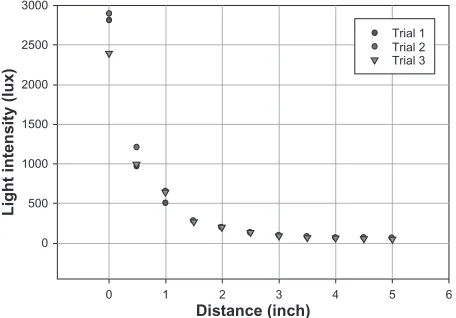
For the preliminary experiments, the intensity of this light source is measured using a lux meter with varying distance and a rubber colon between source and sensor, which is plotted in the following graph. In this, the colonoscope end is fixed, stationary in the rubber colon, and the light sensor is moved away by 0.5 inches (1.25 cm) to measure the light intensity. Figure 4 shows a variation of light intensity with distance. It can be seen that a maximum intensity of light, 2893 lux, occurs when the distance between the source and sensor is zero and the light is directly incident. However,
Figure 3 Twenty-four cadmium sulfide (CdS) photoconductive photocell drivers, which are adjustable for the different intensity of the light source and environment. Only digital values (on/off) are transmitted to the data acquisition system for the localization.
0
0 1 2 3
Distance (inch)
Light intensity (lux)
4
Trial 1 Trial 2 Trial 3
5 6
500 1000 1500 2000 2500 3000
Figure 4 intensity of light source with varying distance.15
Medical Devices: Evidence and Research downloaded from https://www.dovepress.com/ by 118.70.13.36 on 24-Aug-2020
Dovepress Developing the Active Colonoscopy Training Model
such an event will never occur because of the folds of colon coming in between and the colon’s material properties. The localization system is a binary system which requires detect-ing the presence of light irrespective of the intensity of the light source. Another preliminary experiment was conducted to measure the light intensity present inside ACTM with skin cover, Table 1 shows the results. The ACTM was covered by the cloth and the light sensor was kept in 4 different positions. The light sensor was kept inside adjoining to 4 sides of the model. The intensity of light was acquired in lux from the data acquisition system and the results of these experiments yielded that the sensors require a range between 5 and 40 lux intensity of light to locate the distal end of the colonoscope. By taking into consideration the average light intensity of the colonoscopy training model which lies between 10 and 100 lux, the light sensor was selected. CdS photoconductive photocells manufactured by Advanced Photonix, Inc were used as photo sensors to detect the location of the distal end of the colonoscope.15
Pressure measurement
The main objective for the pressure measurement was to find an acceptable pressure transducer capable of measuring colonic pressure. The pressure transducer will initially measure the pressure found within a model of a colon used to test the colonoscopy training model. It was found that researchers and clinicians who wish to study the pressure within the colon do so by using manometric catheters. There are two types in use: solid-state and water infusion. The solid-state manometric catheters use pressure transducers. The water infusion manometric catheters use a balloon tipped catheter that is perfused with water. More recently, systems are now available that use a combination of both methods to study colon pressure. Based upon these findings, acceptable methodology and pressure transducer specifications were established for measuring pressure within our colon model.
In order to measure inside the pressure of the artificial colon, the pressure transducer was installed at the end of the cecum. To create the limited motion of the cecum, the pressure transducer was connected by a 15-cm flexible rubber tube. The pressure transducer was calibrated with the known air pressure
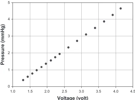
and checked for the validation of the pressure ranges in the artificial colon. The pressure transducer was used initially to measure and record the pressure within the artificial colon during a colonoscopy. The data from the pressure transducer provide information on the degree of safety provided to the colon during the colonoscopy. Figure 5 shows the calibration of the pressure sensor attached at the cecum.
system integration and software
The graphic user interface was implemented using LabView software (see Figure 6). The real time display for the forces and localization of the distal tip has been developed. The real-time display contains information such as the total surgery time, the forces and the air pressure exerted by the colonoscope, and the location of the distal tip inside the artificial colon. The data are automatically saved so that the colonoscopist can see the performance summary after the colonoscopy.
For the hardware, 11 analog-to-digital converters were used to monitor the forces and the pressure and 3 digital input ports used to monitor 24 digital signals for the local-ization. The data acquisition system was powered by USB connector and 6 and 12 volts were applied to the system for the load cell drivers, the photo sensor drivers, and the excitation of the pressure transducer. Analog and digital powers were filtered and separated for the clarity of the power sources.
Ten graphs on the left side display the force profiles from the load cells. The graph on the right upper corner shows the pressure change in the colon at the cecum. The ACTM pictures have 24 indicators, which display the localization of the distal tip, and 2 tables display the times to each part of the colon. Total colonoscopy time is displayed at the upper left corner.
1
0
1.5
1.0 2.0 2.5 3.0
Voltage (volt)
Pressure (mmHg)
3.5 4.0 4.5 2
3 4 5
Figure 5 Calibration of the pressure sensor.
Table 1 Light Intensity (lux) with the Active Colonoscopy Training Model cover15
No. Position 1 Position 2 Position 3 Position 4
1 7.6 6.9 6.2 6.2
2 8.3 6.9 7.6 6.2
3 7.6 6.2 6.2 6.9
Medical Devices: Evidence and Research downloaded from https://www.dovepress.com/ by 118.70.13.36 on 24-Aug-2020
Dovepress
Choi et al
Results
The individual components of the ACTM were tested for validation of functionality. Three main functions were tested: force on the colon wall, pressure inside the artificial colon, and localization of the distal tip. Each experiment was done separately for accurate analysis of the integrated system. The relatively easy configuration of the colon was provided to the expert colonoscopist whose colonoscopy procedure experiences total over 5000.
Force measurement
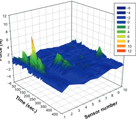
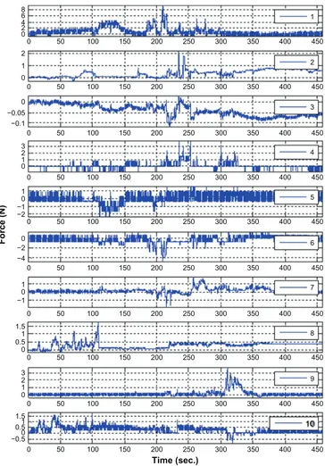
Forces were measured from the beginning to the end of the colonoscopy procedure. Sensor numbers 1, 2, and 3 were located at the sigmoid colon. Sensors 4 to 6 were located in the descending colon. Sensor 7 was at splenic flexure, and sensor 8 was in the middle of the transverse colon. Sensor 9 was at the hepatic flexure and sensor 10 was in the middle of the ascending colon. Figure 7 shows the magnitude of the force vs surgery time for 10 load cells and Figure 8 shows the individual sensor output with respect to the time. Sen-sor 1 showed peak forces from 100 to 250 second region and sensors 4 and 9 also exhibited moderate force values. Sensors number 3, 4, 5, 6, 7, and 10 showed negative forces (compression). Because the ACTM was positioned on its side, which is similar to the position of a real patient during a colonoscopy, the weight of the lubrication fluid and artificial colon were compensated for the zero value.
The colonoscopist tried the ACTM according to the normal colonoscopy procedure and examined the inside of the colon even though the mucosa did not display any bowel diseases. The force profiles after the colonoscopy demonstrated that sensor 1 showed the maximum force of 9.55 N. It occurred when the distal tip was located at the ascending colon. After it passed the hepatic flexure, the colonoscopist needed to push to move forward and even encountered the looping problem. The assistant had to push the ACTM cover to press on the shaft of the colonoscope and Figure 6 interface software using LabView.
12
10
8
6
4
2
0 −2 −4 −6 50
100 150
200 250
300 350
400 450
1 2
3 4
5 6 7 8
9 10
Sensor nu mber
Time (sec.)
Force (N)
−6 −4 −2 0 2 4 6 8 10 12
Figure 7 Force vs time from 10 load cells in the colonoscope training model.
Medical Devices: Evidence and Research downloaded from https://www.dovepress.com/ by 118.70.13.36 on 24-Aug-2020
Dovepress Developing the Active Colonoscopy Training Model
0 0 2 4
0 2 1
0 2 3 1
0
−2 −1
0 −2 −4
0 1
−1 1
1
0 0.5 1.5
1 0 0.5 −0.5 1.5 2
0 1 3 0 −0.05 −0.1 6 8
50 100 150 200 250 300 350 400
1
2
3
4
5
6
7
8
9
10 450
0 50 100 150 200 250 300 350 400 450
0 50 100 150 200 250 300 350 400 450
0 50 100 150 200 250 300 350 400 450
0 50 100 150 200 250 300 350 400 450
0 50 100 150 200 250 300 350 400 450
0 50 100 150 200 250 300 350 400 450
0 50 100 150 200 250 300 350 400 450
0 50 100 150 200 250 300 350 400 450
0 50 100 150 200 250
Time (sec.)
Force (N)
300 350 400 450
Figure 8 Force measurement of each sensor with respect to the operation time.
overcome the looping. The greatest average force through the colonoscopy was 0.85 N from sensor 1. The second peak force of the sensor 1 occurred when the colonoscopist passed the splenic flexure. The lumen of the splenic flexure was closed and the endoscopist had a hard time opening the lumen and passing the splenic flexure. The second greatest force was exerted at sensor 4 when the distal tip passed the ascending colon. Except for sensor 1, the mean values of the forces were all under 0.34 N.
Table 2 shows that sensor 1 had the greatest maximum and sensors 4 and 9 had the second and the third maximum values. Because most of the forces were applied only in the sigmoid, descending, and ascending colon when the distal tip was advanced, mechanical trauma can occur due to the maximum force. Mean value of the force can be represented as fatigue on the mucosa. Sensors 2, 5, 6, 7, 8, and 10 showed the medium value of the maximum forces and sensor 3 showed the lowest value of the maximum forces. Sensor 3
Medical Devices: Evidence and Research downloaded from https://www.dovepress.com/ by 118.70.13.36 on 24-Aug-2020
Dovepress
Choi et al
Table 2 Force test statistics of Active Colonoscopy Training Model (the unit is N)
Sensors 1 2 3 4 5 6 7 8 9 10
Mean 0.850 0.334 -0.039 0.091 -0.029 -0.282 0.162 0.271 0.146 0.304
Max. 9.549 2.202 0.031 3.839 1.629 1.353 1.954 1.775 3.784 1.835
did not interact much and showed the peak value of 0.031 N during the procedure. Again, negative mean values are due to the offset of the colon weight and lubrication.
Localization of the distal tip
After making the connections and attaching the sensors to the rubber colon, a colonoscopy was performed on the training model by an expert colonoscopist. While performing the test, the data were acquired using the data acquisition system. The data were then plotted as shown in Figure 9. The graph, port 1, shows the connections of sensors 1 to 8, and voltage values which indicate that the colonoscope required 75 seconds to pass through the rectum and the sigmoid. It can also be noted that after port 1, port 0 shows voltage values. Sensors 9 to 16 are connected to port 0. This conclusively indicates that the distal end of the colonoscope passed from the descending colon and to the transverse colon in 116 seconds. Figure 9 also shows that port 2 has some voltage values, which shows that the distal end required 49 seconds to pass through the right hepatic flexure and the ascending colon. The voltage data acquired by the data acquisition system, which were decimal values, were converted to 8 bit binary numbers. Eight sensors are connected to each port, namely, port 1, port 2, and port 0. In the above graph, these binary numbers are plotted against corresponding time in seconds. Similarly, during retraction, port 2 indicates voltage values from 4 minutes 7 seconds to 4 minutes 58 seconds. It is followed by port 0, which shows voltage values from 4 minutes 58 seconds to 5 minutes and 48 seconds. After port 0, port 1 shows the presence of the distal end from 5 minutes 48 seconds to 6 minutes 15 seconds. The same information is quantitatively presented in Table 3.
Figure 9 shows that there is some noise at certain places. For instance, port 2 shows some values during the time when the distal end is passing from the rectum to the sigmoid. Since sensors 17 to 24 are connected to port 2, ideally it should not show any value. This occurred because the light from the distal end, when it was in the sigmoid, was also detected by the sensors on the ascending colon. This incident light turned on the sensors connected to port 2, giving some voltage val-ues. But this effect of noise does not affect the localization of the distal end owing to the algorithm described in the method. Figure 9 and Table 3 are examples of analysis of the
colonoscopy test done using the present system. This system cannot give information related to the configuration of the shaft of the colonoscope and cannot determine whether the shape of the colonoscope forms a loop or not.15
Pressure test result
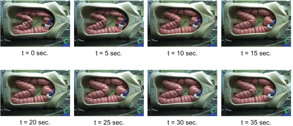
Figure 10 shows the pressure changes in the artificial colon with respect to time. Air was inserted through the colonoscope air duct until the shape of the colon was fully expanded. After the air pressure hit the peak value, the air insertion was stopped and the pressure in the colon decreased. The pressure measured at the cecum started from 0 mmHg and increased to 25 mmHg. The pressure maintained near 20 mmHg and showed a sudden increase after 35 seconds. The artificial anus was pressurized and maintained the loss of air, but some loss was inevitable due to the nature of the artificial organ. In a real procedure, some amount of the inserted air to open up the lumen is expelled through the anus. The only difference is that the artificial anus had continuous loss of air from a sudden level of the air pressure in the colon and the way of expelling the air is more sporadic in a real colonoscopy procedure.
Figure 11 shows the shape change of the artificial colon. Initially, the colonoscopy training model was laid sideways. Because of the weight of the lubricant and the artificial colon itself, there were initially some closed lumen in the colon, especially in the sigmoid colon, the transverse colon, the splenic flexure, and the hepatic flexure. Viacheslav and other researchers claimed that the maximum pressure in the cecum reached up to 120 mmHg but it was not applicable in the arti-ficial colon.21 First, the visco elastic material characteristics are different from human tissue. Human colon tissues can take more stresses in longitudinal directions than transverse directions.22 The volume expansion rates are different for the 2 materials so that the shape changes. To consider the different material characterics, the maximum pressure in the colon had to be scaled down in the artificial colon from 120 to 25 mmHg. However, under 10 mmHg would be more realistic to open up the lumen without excessive volume change of the colon.
Discussion
Most mechanical trauma during colonoscopy procedures are caused by the distal tip or the shaft of the colonoscope.23
Medical Devices: Evidence and Research downloaded from https://www.dovepress.com/ by 118.70.13.36 on 24-Aug-2020
Dovepress Developing the Active Colonoscopy Training Model
250
200
150
100
50
0
0 25 50 75 100 125 150 175 200 225 250 275 300 325 350 375
Time (second) Sensor output (decimal)
Port 0 Port 1 Port 2
Figure 9 Responses of the light sensors.15
Table 3 Localization of the distal tip with time (seconds) and the different parts of the colon15
Location Anus/rectum Sigmoid Decending colon Transverse colon Ascending colon
Advance 0–46 46–75 75–117 117–191 191–240
Retract 348–375 318–348 298–318 279–298 247–279
By monitoring the forces from the colonoscope, a colonoscopist or colonoscope trainee can anticipate an appro-priate force to the colon, and avoid perforation or severe mechanical trauma to mucosa.24 The ACTM kept monitoring and recording the forces during the intubation. In the ACTM, the rectum is fixed at the anus and there was no significant force exerted at the rectum. The sigmoid colon incurred 63.3% of the total average forces throughout the colonoscopy procedure. When the distal tip passed the sigmoid colon, no other parts of the colon were affected except for the ascending colon due to the constraints of the configuration. When the distal tip was in the descending colon, the sigmoid colon incurred forces due to the advancing movement of the colonoscope shaft and the transverse colon showed the peak value. Hepatic flexure showed some stress right after the distal tip was in the ascending colon. The distal tip passed the transverse colon without exerting forces to each part of the colon except for the beginning of the sigmoid colon. The maximum were forces found at the sigmoid colon (sen-sors 1, 2, and 3), the descending colon (sensor 4 and 6), the hepatic flexure (sensor 7), and the splenic flexure (sensor 9) when the distal tip passed the splenic flexure and went into
the ascending colon. No forces were exerted at the cecum because the colonoscopist did not manipulate the dial knobs to scrutinize for ileo-cecal valve or any bowel diseases. The retraction procedure did not stress any part of the colon. Normally, retraction should take several minutes to check for missed bowel diseases but most of the trauma occurred dur-ing the advancement of the colonoscope; the retraction of the colonoscope was quickly performed without observing any bowel diseases. The colonoscopy trainee was kept informed about excess forces thoughout the procedure.
While examining a patient’s digestive system, endoscopes are used to reach and inspect the pancreaticobiliary system. Also, at times doctors are required to insert certain surgical instruments through the working channel of the endoscope to the intended body part.25 For these reasons, information on the location of the distal end of the endoscope is vital from a diagnosis point of view. Image processing is another method employed to locate the position of the desired object. This method is also typically used in endoscopic surgery. This positional information is very useful in surgery to position the surgical instruments in a desired or required manner. This invention signifies an instrument having the
Medical Devices: Evidence and Research downloaded from https://www.dovepress.com/ by 118.70.13.36 on 24-Aug-2020
Dovepress
Choi et al
capability of sending data to the computer. Image processing is a method employed to locate positions and acquire detailed data related to position, which becomes input to robotic devices.26 Many methods have been established to locate the distal tip. The distal end of the endoscope is fixed with a propulsion mechanism and with an energy (electromagnetic/ ultrasonic) wave transmitter at the tip of the endoscope. Along with this, two transducers placed outside of the patient receive the signal and determine the position.27 Determination of the position of probe/distal end is also done using magnetism principles. A magnetic field is generated in the entire volume in which the position is to be determined. The distal end is fit-ted with the sensors which detect the magnetic field. Using the response of the sensors, the distal end can be located.28 The exact position is determined by tracking the field compo-nents detected by the sensors on the probe. Another method
to deduce the position of the probe is to take a direct X-ray, such as a fluoroscopic image. This method has been found to have many disadvantages, as during the procedure the patient is exposed to undesirable radiation. Also this method is inconvenient because the image must be acquired every time the probe moves to a different location. Similarly, ultrasonic principles are also employed to locate the position of the distal end, which is determined from time of flight measurements from an ultrasonic transducer.29 The ultrasound endoscope comprises a radial scan type ultrasound probe along with an endoscope. It is also provided with a rotatable section, and has angle detection means and image rotating means, whereby ultrasound images can be presented on a screen to match the endoscopic observation images at the twisting operations time.30 From the results, the localization of the distal tip was successfully accomplished without introducing the extra equipment in the distal tip or the body of the colonoscope. During the colonoscopy, the trainee did not need to find the mock landmarks in in vitro artificial colon. Total colonoscopy time and each time to the rectum, sigmoid colon, descend-ing colon, splenic flexure, transverse colon, hepatic flexure, ascending colon, and cecum were successfully tabulated in real time base. Retraction speed warning had been given to the trainee if trainee retracted the colonoscope too fast and neglected possible bowel diseases.15
For the pressure measurement, Arkwright et al addressed the current problem with the existing high resolution manom-etry technology, limited to approximately 36 recording sites along the length of the catheter. The new design increases the recording sites to 72, which allows for both high resolu-tion data and longer catheters. In order to achieve this, the
t = 0 sec. t = 5 sec. t = 10 sec. t = 15 sec.
t = 20 sec. t = 25 sec. t = 30 sec. t = 35 sec.
Figure 11 Shape changes of the artificial colon in the Active Colonoscopy Training Model with respect to the pressure increment.
0
0 10 20 30
Time (second)
Pressure (mmHg)
40 50
5 10 15 20 25 30
Figure 10 Air insertion to the Active Colonoscopy Training Model through the colonoscope air channel.
Medical Devices: Evidence and Research downloaded from https://www.dovepress.com/ by 118.70.13.36 on 24-Aug-2020
Dovepress Developing the Active Colonoscopy Training Model
fiber optic sensor array is woven into substrates allowing proper flexibility throughout the length of the catheter. This catheter was used in vivo on 2 subjects. The result was increased accuracy of colonic motility over an extended length of time for the 24-hour recording duration.31 Brandt et al aimed to study the advantages of using CO2 versus air during colonoscopies. The researchers used in vitro models to collect data on colon blood flow, intraluminal pressure of the colon, and A-VO2 differences. They demonstrated that CO2 increased blood flow at transient intraluminal pressures less than 40 mmHg and when intraluminal pressures were held constant between the ranges of 60 to 70 mmHg. In contrast, air decreased colon blood flow at all pressures. The research-ers concluded that colonoscopies should be performed using CO2 to inflate the colon for patients who are at high risk for colon ischemia.32 Hagger et al found contractile correlations within different regions of the colon throughout the duration of 24 hours. The subjects were each fitted with transnasal and transanal catheters containing 5 solid-state pressure transduc-ers each. The region between the cecum and the splenic flexure had significantly increased frequency of contractile activity overall, as well as clusters of contractions that exceeded 90 mmHg in the region between the ascending colon and the splenic flexure prior to the urge to defecate.33 Kozarek et al examined the intraluminal pressures generated during a colonoscopy and compared a standard air–water valve to that of a pressure release valve intended to limit the pressure that was generated by the pump. These two valves were then tested on isolated cadaver sections of the colon: the sigmoid, descending, transverse and ascending colon, and cecum. The standard air-water valve resulted in perforation for all cadaver sections with a maximum pressure range between 120 mmHg in the cecum and 202 mmHg in the sigmoid. Only one cadaver section was ruptured when the pressure release valve was used. Additional clinical cases showed that the pressure release valve decreased in the anus to cecum time by 1 minute. The average and maximum pressures reduced were 9 mmHg and 36 mmHg, respectively.34 The main purpose of the air insertion through the channel is to open up the closed or folded lumen for the better navigation in the colon. Suction can be done to maintain the pressure and remove the water and lubrication to secure the visibility. It also helped to close the lumen. In the ACTM, it takes more time to open up the lumen than in a real patient due to the condition of the rigid artificial colon compared with a human colon. A small amount of air tended to leak continuously through the anus. Since the characteristics in the air which went out from the colon differed between the real patient and the colonoscopy training model, the additional
pressure sensor at the artificial anus would help to monitor the change of the air flow rate. A more precise pressure releasing mechanism and a pressure sensor at the anus are needed to replicate and monitor the function of the anus. During the colonoscopy using ACTM, no significant air usage was found and the pressure in the colon could be ignored compared to the critical value.
Conclusion and future work
Preliminary components of the Active Colonoscopy Train-ing Model to improve the colonoscopy trainTrain-ing skills are presented. Each component, such as force measurement, localization of the distal tip, and the pressure measurement for the safe colonoscopy, was demonstrated with the experiment data and the analysis. The analysis allows the preliminary development and integration of the active colonoscopy train-ing model. For the force from the colonoscope, the maximum and the average forces were found at the various parts of the colon. The sigmoid colon took most of the forces during advancing intubation and the upper limit of the force can be decided after gathering and averaging data values from expert, average, and novice colonoscopists. The light source on the colonoscope was utilized to detect the position of the distal tip using light sensors in the artificial colon. The local-ization of the distal tip helped to provide an understanding of the intubation processes. The colonoscopy time was mea-sured to reach each part of the colon to measure colonoscopy skill with a realistic colonoscopy environment. The pressure inserted through the colonoscope channel was continuously measured at the cecum to evaluate for excessive pressure. The difference between the published maximum pressure in the human colon and that of the artificial colon was discussed and a suitable maximum pressure range in the artificial colon was determined to open up the lumen. Integrated software was developed to summarize the performance of the colonosco-pist, which includes the total colonoscopy time (for advance and withdrawal), intubation time for each part of the colon, the maximum and average forces on each part of the colon, and the maximum pressure recorded. The research will be continued with a focus on the evaluation of the ACTM to achieve the clinical correlation for different skill levels of the colonoscopist. More detailed values (maximum and minimum thresholds) of each parameter (force, pressure, and time) will be decided by the performances based of the clinical results.
Disclosure
The authors report no conflicts of interest in this research.
Medical Devices: Evidence and Research downloaded from https://www.dovepress.com/ by 118.70.13.36 on 24-Aug-2020
Medical Devices: Evidence and Research
Publish your work in this journal
Submit your manuscript here: http://www.dovepress.com/medical-devices-evidence-and-research-journal
Medical Devices: Evidence and Research is an international, peer-reviewed, open access journal that focuses on the evidence, technology, research, and expert opinion supporting the use and application of medical devices in the diagnosis, treatment and management of clini-cal conditions and physiologiclini-cal processes. The identification of novel
devices and optimal use of existing devices which will lead to improved clinical outcomes and more effective patient management and safety is a key feature. The manuscript management system is completely online and includes a quick and fair peer-review system. Visit http://www. dovepress.com/testimonials.php to read real quotes from authors.
Dovepress
Dove
press
Choi et al
References
1. Byers T, Levin B, Rothenberger D, Dodd GD, Smith RA. American Cancer Society Guidelines for screening and surveillance for early detection of colorectal polyps and cancer. CA Cancer J Clin. 1997;47(3): 154–160.
2. Jones IT. Training in colonoscopy: a personal view. Aust N Z J Surg. 1998;68(5):316–317.
3. Raman M, Donnon T. Procedural skills education – colonoscopy as a model. Can J Gastroenterol. 2008;22(9):767–770.
4. Bar-Meir S. A new endoscopic simulator. Endoscopy. 2000;32(11): 898–900.
5. Sedlack RE, Baron TH, Downing SM, Schwartz AJ. Validation of a colonoscopy simulation model for skills assessment. Am J Gastroenterol. 2007;102(1):64–74.
6. Felsher JA, Olesevich M, Farres H, et al. Marks validation of a flexible endoscopy simulator. Am J Surg. 2005;189(4):497–500.
7. Grantcharov TP, Carstensen L, Schulze S. Objective assessment of gastrointestinal endoscopy skills using a virtual reality simulator. JSLS. 2005;9(2):130–133.
8. Tsang JS, Naughton PA, Leong S, Hill AD, Kelly CJ, Leahy AL. Virtual reality simulation in endovascular surgical training. Surgeon. 2008;6(4):214–220.
9. Haycock A, Koch AD, Familiari P, et al. Training and transfer of colonoscopy skills: a multinational, randomized, blinded, controlled trial of simulator versus bedside training. Gastrointest Endosc. 2010;71(2): 308–311.
10. Mahmood T, Darzi A. A study to validate the colonoscopy simulator. Surg Endosc. 2003;17(10):1583–1589.
11. Kim S, Spencer G, Makar GA, et al. Lack of a discriminatory function for endoscopy skills on a computer-based simulator. Surg Endosc. 2010;24(12):3008–3015.
12. Mahmood T, Darzi A. The learning curve for a colonoscopy simulator in the absence of any feedback: no feedback, no learning. Surg Endosc. 2004;18(8):1224–1230.
13. Woojin Ahn, Woo Seok Kim, Hyun Soo Woo, et al. Colonoscopy simulator with enhanced haptic realism and visual feedback. World Congress on Medical Physics and Biomedical Engineering. 2006;14(6): 3820–3823.
14. Hellier D, Samur E, Passenger J, et al. A modular simulation framework for colonoscopy using a new haptic device. Stud Health Technol Inform. 2008;132:165–170.
15. Kale R, Choi JH. Localization of the distal itp in the colonoscopy training model using light sensors, Proceedings of the 2011 Design of Medical Devices Conference. 2011, Apr 12–14; Minneapolis, MN, USA.
16. Bhatnager BNS, Sharma CLN, Gupta SN, Mathur MM, Reddy DCS. Study on the anatomical dimensions of the human sigmoid colon. Clin Anat. 2004;17(3):236–243.
17. Madiba TE, Haffajee MR. Anatomical variations in the level of origin of the sigmoid colon from the descending colon and the attachment of the sigmoid mesocolon. Clin Anat. 2004;23(2):179–185.
18. Wehrmeyer JA, Barthel JA, Roth JP, Saifuddin T. Colonoscope flexural rigidity measurement. Med Biol Eng Comput. 1998;36(4):475–479. 19. Hawari R. Going for the loop: a unique overtube for the difficult
colonoscopy. J Clin Gastroenterol. 2007;41(2):138–140.
20. Dogramadzi S. Recording forces exerted on the bowel wall during colonoscopy: in vitro evaluation. Int J Med Robot Comput Assist Surg. 2005;1(4):89–97.
21. Viacheslav I, Egorov IV. Mechanical properties of the human gastrointestinal tract. J Biomech. 2002;35(10):1417–1425.
22. Yamada H. Yamada. Strength of Biological Materials. 2nd ed. Baltimore: Williams and Watkins; 1972.
23. Swanstrom LL, Kozarek R, Pasricha PJ, et al. Development of a new access device for transgastric surgery. J Gastrointest Surg. 2005;9: 1129–1137.
24. Brouwer I, Ustin J, Bentley L, Sherman A, Dhruv N, Tendick F. Measuring in vivo animal soft tissue properties for haptic modeling in surgical simulation. In: Medicine Meets Virtual Reality 2001, IOS Press; 2001:69–74.
25. Wood M, Leanna GJ. Medical device positioning system. United States patent 7753843. July 13, 2010.
26. Frazer RE. Apparatus for endoscopic examination. United States patent 4176662. December 4, 1979,
27. Funda J, LaRose T. Robotic system for positioning a surgical instrument relative to a patient’s body. United States patent 5572999. November 12, 1996.
28. Acker DE, Charidimos E. Gasparakis method and apparatus for determin-ing position of object. United States patent 5752513. May 19, 1998. 29. Acker DE, McNulty Pacheco RC, Grandner W. Magnetic determination
of position and orientation. United States patent 5558091. September 24, 1996.
30. Itoi H. Ultrasound endoscope having ultrasound probe in combination with endoscopic observation system. United States patent 5671748. September 30, 1997.
31. Arkwright JW, Underhill ID, Maunder SA, Blenman N, Szczesniak MM, Wiklendt L. Design of a high-sensor count fibre optic manometry catheter for in-vivo colonic diagnostics. Opt Express. 2009;17(25): 22423–22431.
32. Brandt LJ, Boley SJ, Sammertano R. Carbon dioxide and room air insufflation of the colon. Gastrointest Endosc. 1986;32(5):324–329. 33. Hagger R, Kumar D, Grundy A. Periodic colonic motor activity
identified by 24-h pancolonic ambulatory manometry in humans. Neurogastroenterol Motil. 2002;14(3):271–278.
34. Kozarek RA, Sanowski RA. Use of pressure release valve to prevent colonic injury during colonoscopy. Gastrointest Endosc. 1980;26(4): 139–142.
Medical Devices: Evidence and Research downloaded from https://www.dovepress.com/ by 118.70.13.36 on 24-Aug-2020