Assessment of Seismic Forces by Equivalent
Static Force Analysis as Per IS 1893(Part I):
2002
Chetan Jaiprakash Chitte
Assistant Professor,Dept. of Civil Engineering
RCPIT, Shirpur, Maharsahtra, India
Yogesh N. Sonawane
Assistant Professor,Dept. of Civil Engineering
RCPIT, Shirpur, Maharsahtra, India
Abstract-Experience in past earthquakes has demonstrated that many common buildings and typical methods of construction lack basic resistance to earthquake forces. In most cases this resistance can be achieved by following simple, inexpensive principles of good building construction practice. Apart from gravity loads, the structure will experience dominant lateral forces of considerable magnitude during earthquake shaking. It is essential to estimate and specify these lateral forces on the structure in order to design the structure to resist an earthquake. It is impossible to exactly determine the earthquake induced lateral forces that are expected to act on the structure during its lifetime. However, considering the consequential effects of earthquake due to eventual failure of the structure, it is important to estimate these forces in a rational and realistic manner. This paper describes equivalent static force analysis procedure as per IS 1893(PART I): 2002 for four storey RCC building.
Keywords – Equivalent static analysis, Design horizontal seismic coefficient, Seismic base shear, Fundamental period
I.INTRODUCTION
Apart from gravity loads, the structure will experience dominant lateral forces of considerable magnitude during earthquake shaking. It is essential to estimate and specify these lateral forces on the structure in order to design the structure to resist an earthquake. It is impossible to exactly determine the earthquake induced lateral forces that are expected to act on the structure during its lifetime. However, considering the consequential effects of earthquake due to eventual failure of the structure, it is important to estimate these forces in a rational and realistic manner. Objective of study is to determine earthquake lateral forces by Equivalent static force analysis as per IS 1893(PART I): 2002 for four storey RCC building.
II. EARTHQUAKE DESIGN PHILOSOPHY
The earthquake design philosophy may be summarized as follows (Figure 1): (a) Under minor but frequent shaking, the main members of the building that carry vertical and horizontal forces should not be damaged; however building parts that do not carry load may sustain repairable damage. (b) Under moderate but occasional shaking, the main members may sustain repairable damage, while the other parts of the building may be damaged such that they may even have to be replaced after the earthquake; and (c) Under strong but rare shaking, the main members may sustain severe (even irreparable) damage, but the building should not collapse.
Thus, after minor shaking, the building will be fully operational within a short time and the repair costs will be small. And, after moderate shaking, the building will be operational once the repair and strengthening of the damaged main members is completed. But, after a strong earthquake, the building may become dysfunctional for further use, but will stand so that people can be evacuated and property recovered.
Fig -1: Diagram showing earthquake resistant design philosophy
III GENERAL PRINCIPLES & DESIGN CRITERIA OF EARTHQUAKE RESISTANT DESIGN BY IS 1893(PART I): 2002
3.1 General Principles:
Clause 6.1(Pg.12) of IS 1893(PART I): 2002 provides the following design principles,
The random earthquake ground motions, which cause the structure to vibrate, can be resolved in any three mutually perpendicular directions. The predominant direction of ground vibration is usually horizontal.
Earthquake-generated vertical inertia forces are to be considered in design unless checked and proven in specimen calculations to be not significant. Vertical acceleration should be considered in structures with large spans and those in which stability is a criterion for design. Reduction in gravity force due to vertical component of ground motions can be particularly detrimental in cases of prestressed horizontal members and of cantilevered members. Hence, special attention should be paid to the effect of vertical component of the ground motion on prestressed or cantilevered beams, girders and slabs.
The response of a structure to ground vibration is a function of the nature of foundation soil: materials, form, size and mode of construction of structures and the duration and characteristics of ground motion. IS-1893 specifies design forces for structures standing on rocks or soils which do not settle or liquefy or slide due to loss of strength during ground vibrations.
The design approach adopted in IS 1893 ensures that structures possess at least a minimum strength to withstand minor earthquakes of intensity less than DBE (Design Basis Earthquake) without damage; resist moderate earthquakes equal to DBE without significant structural damage though some non-structural damage may occur; and aims that structures withstand a major earthquake (Maximum Considered Earthquake - MCE) without collapse.
Actual forces that appear on structures during earthquakes are much greater than the design forces specified in the code. However, ductility, arising from inelastic material behaviour and detailing, and over strength, arising from the additional reserve strength in structures over and above the design strength, are relied upon to account for this difference in actual and design lateral loads.
The design lateral force specified in this standard shall be considered in each of the two orthogonal horizontal directions of the structure. For structures which have lateral force resisting elements in the two orthogonal directions only, the design lateral force shall be considered along one direction at a time, and not in both directions simultaneously.
Structures, having lateral force resisting elements (for example frames, shear walls) in directions other than the two orthogonal directions, shall be analysed considering the load combinations specified in Clause: 6.3.2 [IS 1893(PART I): 2002]. Where both horizontal and vertical seismic forces are taken into account, load combinations specified in Clause: 6.3.3 [IS 1893(PART I): 2002] shall be considered. (Refer to equation (3) & (4) for load combinations specified in IS-1893)
(Clause: 6.2, Pg. 13, IS 1893(PART I): 2002):
Earthquake causes impulsive ground motions, which are complex and irregular in character, changing in period and amplitude each lasting for a small duration. Therefore, resonance of the type as visualised under steady-state sinusoidal excitations, will not occur as it would need time to build up such amplitudes
Earthquake is not likely to occur simultaneously with wind or maximum flood or maximum sea waves.
The value of elastic modulus of materials, wherever required, may be taken as for static analysis unless a more definite value is available for use in such condition
3.3 Load combinations in Earthquake Resistant Design of Structures:
Clause: 6.3, Pg.13 of IS 1893(PART I): 2002 specifies following load combinations.
In the plastic design of steel structures, the following load combinations shall be accounted for: 1) 1.7(DL+IL)
2) 1.7(DL+/- EL) 3) 1.3( DL+IL+/-EL)
In the limit state design of reinforced and prestressed concrete structures, the following load combinations shall be accounted for:
1) 1.5(DL+IL) 2) 1.2(DL+IL+/-EL) 3) 1.5(DL+/-EL) 4) 0.9DL+/-1.5EL
Where DL, IL and EL denote dead load, imposed load and earthquake load respectively. 3.3.1 Design Horizontal Earthquake Load:
When the lateral load resisting elements are oriented along orthogonal horizontal direction, the structure shall be designed for the effects due to full design earthquake load in one horizontal direction at time.
When the lateral load resisting elements are not oriented along the orthogonal horizontal directions, the structure shall be designed for the effects due to full design earthquake load in one horizontal direction plus 30 percent of the design earthquake load in the other direction
3.3.2 Design Vertical Earthquake Load:
When effects due to vertical earthquake loads are to be considered, the design vertical force shall be calculated in accordance with Clause: 6.4.5 of IS 1893(PART I): 2002. (i.e., the design acceleration spectrum for vertical motions may be taken as two-thirds of the design horizontal acceleration spectrum). 3.3.3 Combination for Two or Three Component Motion:
When responses from the three earthquake components are to be considered, the responses due to each component may be combined using the assumption that when the maximum response from one component occurs, the responses from the other two components are 30 percent of their maximum. All possible combinations of the three components (ELx, ELy and ELz where x and y are two orthogonal directions and z is vertical direction) including variations in sign (plus or minus) shall be considered. Thus, the response due earthquake force (EL) is the maximum of the following three cases (Clause: 6.3.4.1, IS 1893(PART I): 2002)
where x and y are two orthogonal directions and z is vertical direction.
Or as an alternative to the procedure mentioned above, the response (EL) due to the combined effect of the three components can be obtained (Clause: 6.3.4.2, IS 1893(PART I): 2002) on the basis SRSS that is,
3.4 Design Spectrum:
Provided that for any structure with T<=0.1s, the value of Ah will not be taken less than Z/2 whatever be the value of I/R. Where
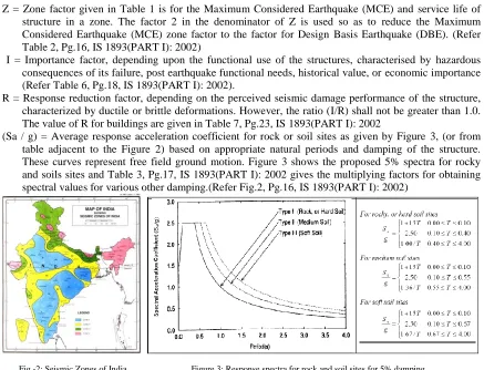
Z = Zone factor given in Table 1 is for the Maximum Considered Earthquake (MCE) and service life of structure in a zone. The factor 2 in the denominator of Z is used so as to reduce the Maximum Considered Earthquake (MCE) zone factor to the factor for Design Basis Earthquake (DBE). (Refer Table 2, Pg.16, IS 1893(PART I): 2002)
I = Importance factor, depending upon the functional use of the structures, characterised by hazardous consequences of its failure, post earthquake functional needs, historical value, or economic importance (Refer Table 6, Pg.18, IS 1893(PART I): 2002).
R = Response reduction factor, depending on the perceived seismic damage performance of the structure, characterized by ductile or brittle deformations. However, the ratio (I/R) shall not be greater than 1.0. The value of R for buildings are given in Table 7, Pg.23, IS 1893(PART I): 2002
(Sa / g) = Average response acceleration coefficient for rock or soil sites as given by Figure 3, (or from table adjacent to the Figure 2) based on appropriate natural periods and damping of the structure. These curves represent free field ground motion. Figure 3 shows the proposed 5% spectra for rocky and soils sites and Table 3, Pg.17, IS 1893(PART I): 2002 gives the multiplying factors for obtaining spectral values for various other damping.(Refer Fig.2, Pg.16, IS 1893(PART I): 2002)
Fig -2: Seismic Zones of India Figure 3: Response spectra for rock and soil sites for 5% damping [Fig.1, Pg. 5 of IS-1893 (2002)] [Fig. 2, Pg.16, IS 1893(PART I): 2002]
Table 1: Zone factor (Z) [Table 2, Pg. 16, IS 1893 (PART I): 2002]
Table 2: Importance factor (I) [Table 6, Pg. 18, IS 1893(PART I): 2002]
Table 4: Response reduction factor (R) for building systems [Table 7, Pg.23, IS 1893(PART I): 2002]
3.5 Design imposed loads for earthquake force calculation [Clause 7.3, IS 1893(PART I): 2002]
For various loading classes as specified in IS 875 (Part 2), the earthquake force shall be calculated for the full dead load plus the percentage of imposed load as given in Table 5.
IV. DESIGN LATERAL FORCES
4.1 Design Seismic Base Shear:
The total design lateral force or design seismic base shear (VB) along any principal direction shall be determined by the following expression: [Clause 7.5.3, IS 1893(PART I): 2002]
VB = AhW Where,
Ah = Design horizontal acceleration spectrum value as per cl.6.4.2, using the fundamental natural period Ta as per Cl.7.6 of IS 1893(PART I): 2002 in the considered direction of vibration; and
W = Seismic weight of the building is computed as given below [Clauses 7.4.2 & 7.4.3, IS 1893(PART I): 2002]
Seismic Weight of floors:
The seismic weight of each floor is its full dead load plus appropriate amount of imposed load. While computing the seismic weight of each floor, the weight of columns and walls in any storey shall be equally distributed to the floors above and below the storey.
Seismic Weight of Building:
The seismic weight of the whole building is the sum of the seismic weights of all the floors.
Any weight supported in between storeys shall be distributed to the floors above and below in inverse proportion to its distance from the floors.
4.2 Fundamental Period:
4.2.1 The approximate fundamental natural period of vibration (Ta), in seconds, of a moment resisting frame building without brick infill panels may be estimated by the empirical expression: [Clause 7.6.1, IS 1893(PART I): 2002]
Ta=0.075h0.75---- (for RC frame building) Ta=0.085 h
0.75
---- (for steel frame building)
4.2.2 The approximate fundamental natural period of vibration (Ta), in seconds, of all other buildings, including moment-resisting frame buildings with brick infill panels, may be estimated by the empirical expression: [Clause 7.6.2, IS 1893(PART I): 2002]
Ta =0.09/√d Where,
h = Height of building, in m. This excludes the basement storeys, where basement walls are connected with the ground floor deck or fitted between the building columns. But, it includes the basement storeys, when they are not so connected.
d = Base dimension of the building at the plinth level, in m, along the considered direction of the lateral force.
V. EARTHQUAKE LATERAL FORCE ANALYSIS
The design lateral force shall first be computed for the building as a whole. This design lateral force shall then be distributed to the various floor levels. The overall design seismic force thus obtained at each floor level shall then be distributed to individual lateral load resisting elements depending on the floor diaphragm action. There are two commonly used procedures for specifying seismic design lateral forces:
1. Equivalent static force analysis 2. Dynamic analysis
5.1 Equivalent static force analysis:
The equivalent lateral force for an earthquake is a unique concept used in earthquake engineering. The concept is attractive because it converts a dynamic analysis into partly dynamic and partly static analyses for finding the maximum displacement (or stresses) induced in the structure due to earthquake excitation. For seismic resistant design of structures, only these maximum stresses are of interest, not the time history of stresses. The equivalent lateral force for an earthquake is defined as a set of lateral static forces which will produce the same peak response of the structure as that obtained by the dynamic analysis of the structure under the same earthquake. This equivalence is restricted only to a single mode of vibration of the structure. Inherently, equivalent static lateral force analysis is based on the following assumptions,
Assume that structure is rigid.
Dominant effect of earthquake is equivalent to horizontal force of varying magnitude over the height.
Approximately determines the total horizontal force (Base shear) on the structure. However, during an earthquake structure does not remain rigid, it deflects, and thus base shear is disturbed along the height. The limitations of equivalent static lateral force analysis may be summarized as follows,
In the equivalent static force procedure, empirical relationships are used to specify dynamic inertial forces as static forces.
These empirical formulas do not explicitly account for the dynamic characteristics of the particular structure being designed or analyzed.
These formulas were developed to approximately represent the dynamic behavior of what are called regular structures (Structures which have a reasonably uniform distribution of mass and stiffness). For such structures, the equivalent static force procedure is most often adequate.
Structures that are classified as irregular violate the assumptions on which the empirical formulas, used in the equivalent static force procedure, are developed.
Common types of irregularities in a structure include large floor-to-floor variation in mass or center of mass and soft stories etc. Therefore in such cases, use of equivalent static force procedure may lead to erroneous results. In these cases, a dynamic analysis should be used to specify and distribute the seismic design forces.
5.2 Dynamic Analysis
Dynamic analysis is classified into two types, namely, Response spectrum method and Time history method Dynamic analysis shall be performed to obtain the design seismic force, and its distribution to different levels along the height of the building and to the various lateral load resisting elements, for the following buildings:
a) Regular buildings — Those greater than 40 m in height in Zones IV and V, and those greater than 90 m in height in Zones II and III.
b) Irregular buildings — All framed buildings higher than 12 m in Zones IV and V, and those greater than 40 m in height in Zones II and III.
In this paper, earthquake lateral forces are determined by Equivalent static force analysis
VI. STEP BY STEP PROCEDURE FOR EQUIVALENT STATIC FORCE ANALYSIS
Step-1: Depending on the location of the building site, identify the seismic zone and assign Zone factor (Z) using Table 2 along with Seismic zones map or Annex of IS 1893(PART I): 2002
Step-2: Compute the seismic weight of the building (W).
Seismic weight of floors is computed as per Clause 7.4.2, IS 1893(PART I): 2002
Seismic weight of the building is computed as per Clause 7.4.3, IS 1893(PART I): 2002
Step-3: Compute the natural period of the building (Ta) as per Clause 7.6.1 or Clause 7.6.2, IS 1893(PART I): 2002, as the case may be.
Step-4: Obtain the data pertaining to type of soil conditions of foundation of the building
Assign type, I for hard soil, II for medium soil & III for soft soil
Step-5: Using Ta and soil type (I / II / III), compute the average spectral acceleration (Sa/g).
Use Figure 2 or corresponding table of IS 1893(PART I): 2002, to compute (Sa/g).
Step-6: Assign the value of importance factor (I) depending on occupancy and/or functionality of structure
As per Clause 7.2 and Table 6 of IS 1893(PART I): 2002
Step-7: Assign the values of response reduction factor (R) depending on type of structure
As per Clause 7.2 and Table 7 of IS 1893(PART I): 2002
Step-8: Knowing Z, Sa/g, R and I compute design horizontal acceleration coefficient (Ah) using the relationship, Ah=(Z/2) (Sa/g)(I/R) [Clause 6.4.2, IS-1893 (2002)]
Step-9: Using Ah and W compute design seismic base shear (VB), from VB =Ah.W [Clause7.5.3, IS-1893 (2002)]
Step-10: Compute design lateral force (Qi) of ith floor by distributing the design seismic base shear (VB) as per the expression,
VII. PROBLEM STATEMENT
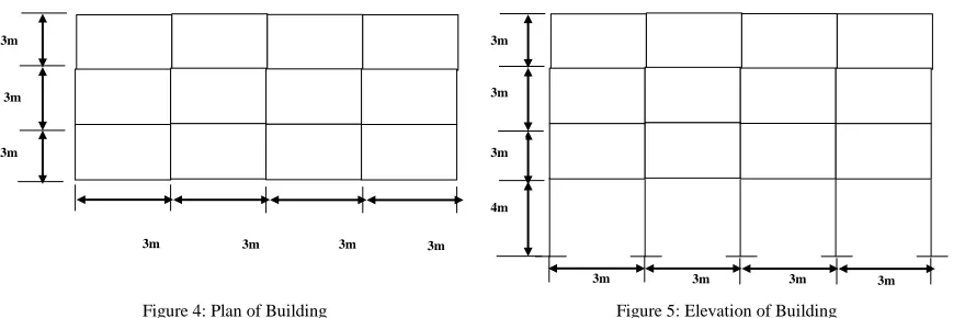
Consider a four-storey reinforced concrete office building shown in Fig. The building is located in Nasik (seismic zone III). The R. C. frames are in filled with brick-masonry. The lumped weight due to dead loads is 12 KN/m2 on floors and 10 KN/m2 on the roof. The floors are to cater for a live load of 4 KN/m2 on floors. Determine design seismic load on the structure.
Figure 4: Plan of Building Figure 5: Elevation of Building
7.1 GIVEN CONDITION:- No. of Storey = 4
Location - Nasik (Seismic zone III) Dead Load - On Floor = 12 KN/m2 On Roof = 10 KN/m2 Live Load - On Floor = 4 KN/m2
7.2 DESIGN PARAMETERS:- For Seismic Zone III
Zone Factor, Z=0.16 (Moderate) [Table-2 Pg no. 16, IS1893 (Part I): 2002] Importance Factor, I =1.0 [Table-6 Pg no. 18, IS 1893 (Part I): 2002]
Response Reduction Factor, R = 5 [Special Moment Resisting frame] [Table -7 Pg no. 23, IS1893 (Part I)] 7.3 SEISMIC WEIGHTS:
Floor area is 9 x 12 = 108 sq. m. Since the live Load class is 4kN/sq.m, only 50% of the live load is lumped at the floors. At roof, no live load is to be lumped. Hence, the total seismic weight on the floors and the roof is:
Floor Area = 9 x 12 = 108mm2 Seismic Weight on Floor
W1=W2= W3= 108 x (12 + 0.5 x 4) = 1512 KN
[Above 3 storey live load must be add up to 50% of live load, Table -8 Pg.No.24, IS1893 (Part I): 2002] On Roof, W4= 108 x 10 = 1512 KN
Total Seismic Weight on Structure W = W1+W2+W3+W4 W = 3 x 1512 + 1080 W = 5616 KN EL in x direction:
7.4 FUNDAMENTAL PERIOD:-
[Cl. 7.6.2 Pg no.24, IS 1893 (Part I):2002] T = 0.09h /√ d
= 0.09 x 13/√12 = 0.3337 sec.
The Building Is Located On Type II (Medium Soil) Sa/g (Spectral acceleration coefficient)
For T= 0.3337, Sa/g = 2.5 [From Fig 2 Pg No. 16, IS1893 (Part I): 2002]
3m
3m
3m
3m
3m
3m
4m
7.5 DESIGN HORIZONTAL SEISMIC COEFFICIENT [Ah] Ah= (ZI/2R)(Sa/g)
Ah = 0.16 x 1 x 2.5 [Cl 6.4.2 Pg 14, IS1893 (Part I): 2002] 2 x 5
Ah = 0.04 7.6 DESIGN BASE SHEAR
VB = AhW [Cl 7.5.3 Pg 24, IS1893 (Part I): 2002] = 0.04 x 5616
= 224.64 KN EL in Y- direction
T= (0.09 h /√d) T = (0.09 x 13/√ 9)
T = 0.39
Sa/g = 2.5 & Ah = 0.04
Therefore, for this building the design seismic force in Y-direction is same as that in the X-direction
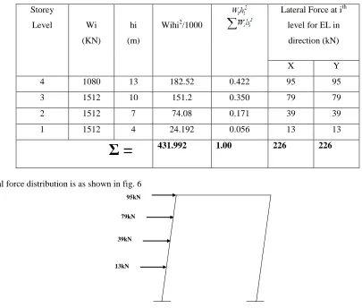
7.7 FORCE DISTRIBUTION WITH BUILDING HEIGHT:
The design base shear is to be distributed with height as per clause 7.7.1, Pg.24, IS1893 (Part I): 2002. Table 6 gives the calculations. Fig. 6 shows the design seismic force in X & Y-direction for the entire building.
Storey lateral forces and shear forces are calculated and tabulated in the following table.
Table 6: Lateral Load Distribution with Height by the Static Method
Storey
Level Wi
(KN)
hi
(m)
Wihi2/1000
Lateral Force at ith
level for EL in
direction (kN)
X Y
4 1080 13 182.52 0.422 95 95
3 1512 10 151.2 0.350 79 79
2 1512 7 74.08 0.171 39 39
1 1512 4 24.192 0.056 13 13
Ʃ =
431.992 1.00 226 226Lateral force distribution is as shown in fig. 6
Fig. 6: Design of seismic lateral forces in X and Y direction
95kN
79kN
VII
CONCLUSION
Equivalent static force analysis approach defines a series of forces acting on a building to represent the effect of earthquake ground motion, typically defined by a seismic design response spectrum.
It assumes that the building responds in its fundamental mode. For this to be true, the building must be low-rise and must not twist significantly when the ground moves.
The response is read from a design response spectrum, given the natural frequency of the building (either calculated or defined by the building code).
The applicability of this method can be extended in many building codes by applying factors to account for higher buildings with some higher modes, and for low levels of twisting.
Equivalent static force analysis is not suitable for high rise buildings.
REFERENCES
[1] Agarwal P. and M Shrikhande (2007), “Earthquake Resistant Design of Structures”, Prentice Hall of India Pvt. Ltd., 2007, New Delhi. [2] IITK-BMTPC (2004), “Earthquake Tip #8 – What is the Seismic Design Philosophy for Buildings?” 2004, www.nicee.org, IIT-Kanpur. [3] IS 1893 (Part 1)- 2002, “Criteria For Earthquake Resistant Design Of Structures - Part 1 General Provisions And Buildings”, 5th Revision,
2002, BUREAU OF INDIAN STANDARDS, New Delhi, INDIA

![Table 4: Response reduction factor (R) for building systems [Table 7, Pg.23, IS 1893(PART I): 2002]](https://thumb-us.123doks.com/thumbv2/123dok_us/1422390.1655566/5.612.153.458.72.118/table-response-reduction-factor-building-systems-table-pg.webp)