Volume 7, Issue 5 [Jun 2018] PP: 44-62
Heat Transfer Studies on Plate Type Heat Exchanger Using
Miscible And Immiscible Liquids
S.Ganapathy
1, N.Tamilselvan
21Department of Mechanical Engineering, Excel Engineering College, Komarapalayam, Corresponding Author: S.Ganapathy
ABSTRACT: Heat exchangers are used extensively and regularly in process and allied industries and are very important during design and operation. The choice of heat exchanger type directly affects the process performance and also influences plant size, plant layout, length of pipe runs, and the strength and size of supporting structures. Compact heat exchangers are characterized by having a comparatively large surface area to a given volume, when compared with traditional heat exchangers, in particular the shell and tube type. Two-phase (liquid-liquid) flow is frequently encountered in chemical process industries. In the present work the performance of plate type heat exchanger have been studied experimentally and comparison was made between the co-current and counter-current flow pattern with different cold side fluids that involve both immiscible and miscible systems. Hot water was taken as the hot side fluid for all the experimentation. The cold fluids used were water, kerosene-water system, acetic acid-water system of different compositions say 9%, 10%, 20% and 25% on volume basis in different flow rates. Also the flow rate of cold fluid was varied to find the effect of flow rate and composition on heat transfer coefficients, effectiveness and efficiencies. The hot fluid flow rate was kept constant at 1lpm and the cold fluid flow rate was varied from 12.5 to 42.5 lph. The above experiments indicate that the plate type heat exchanger performs well when operated under counter current flow pattern.
KEYWORDS: Water-Kerosene, Water – Acetic acid
--- --- Date of Submission: 06-06-2018 Date of acceptance: 21-06-2018 ---
---I. INTRODUCTION
A heat exchanger is process equipment used for transferring heat from one fluid to another fluid through a separating wall. “When none of the fluid condenses or evaporates, the unit is called as Heat Exchanger." In this only the sensible heat transfers from the one fluid to another. They are widely used in petroleum refineries, chemical plants, petrochemical plants, natural gas processing, refrigeration, power plants, air conditioning and space heating. Heat exchangers could be classified in many different ways such as according to flow arrangements, number of fluids, surface compactness, process function, heat transfer mechanisms, type of fluids (gas-gas, gas-liquid, liquid-liquid, gas-two-phase, liquid-two-phase, etc.) and construction type (R.K. Shah et.al.,2000). There are several types of heat exchanger:
Recuperative type, in which fluids exchange heat on either side of a dividing wall
Regenerative type, in which hot and cold fluids occupy the same space containing a matrix of material that works alternatively as a sink or source for heat flow
Evaporative type, such as cooling tower in which a liquid is cooled evaporatively in the same space as coolant.
1.1 OBJECTIVE OF THE PROPOSED WORK
The experimental work in plate type heat exchanger (Parallel and Counter flow) involved in the determination of outlet temperature of both cold and hot fluid for various flow rates. The water system, water-acetic acid system, and water-kerosene system at 9%, 10%, 20% and 25% composition on volume basis of kerosene and acetic acid, were used to determine the performance of plate type heat exchanger. i.e. overall heat transfer coefficient (U0), effectiveness (ε), cold side efficiency (ηc) and hot side efficiency (ηh).
II. PLATE TYPE HEAT EXCHANGER 2.1EXPERIMENTAL STUDIES
2.2 Experimental Set-up
The plate type heat exchanger under study consists of 5 plates and 2 end plates made of Aluminium of dimensions, 150 mm x150 mm inner dimension and 250 mm x 250 mm outer dimension. The heat transfer plates are arranged to form a network of parallel or counter flow channels. The plate pack is mounted on upper and lower rails and compressed between two end frames using compression bolts. The hot fluid is hot water which is obtained from an electric geyser and it flows through one plate while the cold fluid is flowing through the other plate. The hot water flows always in one direction and the flow rate is controlled by means of a gate valve. The cold water can be admitted at one of the ends enabling the heat exchanger to run as a parallel flow apparatus or a counter flow apparatus by simple valve operation.
2.3 HEAT EXCHANGER SPECIFICATIONS
No. of plates: 5 plates and 2 end plates.
Size of the plate: outer diameter 215 mm x 215 mm inner diameter 150 mm x 150 mm.
Material: Aluminium
Gasket: silicon 6 nos.
Temperature scanner 5 point 1 nos.
Thermocouple 4 nos. 2 nos. for cold water inlet and outlet, 2 nos. for hot water inlet and outlet.
Measuring tank 70mm in diameter length 500 mm 2nos.
Stop watch- digital- 1 no.
Geyser- single phase 230v-3kW-2 nos. total 6 nos. with main switch
Insulation material: Asbestos
2.4 EXPERIMENTAL PROCEDURE
The experimental setup was operated in counter-current flow pattern by adjusting thevalves. The flow of water on hot side was started. The flow rate of water entering the hot side of exchanger was adjusted with the help of a ball valve.
The geysers were switched ON and waited till temperature reaches a steady state. The temperature scanner was switched ON and inlet temperature of hot side (T1) was noted. The pumps were operated and the rotameters on
cold side were adjusted to get the required flow rate of cold fluid with required composition (9% or 10% or 20% or 25% on the basis of volume).
The inlet temperature of cold fluid (t1) was noted from temperature scanner. The flow rates on the hot and
was repeated for different compositions and different systems (Kerosene-Water, Acetic acid-Water). Similar procedure was followed for the co-current flow operation.
2.5 EXPERIMENTAL OBSERVATION 2.5.1 Counter Current Flow Pattern
2.5.1.1 IMMISCIBLE SYSTEMS
Volumetric flow rate of cold fluid lph
Volumetric flow rate of hot fluid lpm
Inlet Temperature °C
Outlet Temperature °C Cold
Fluid Hot Fluid
Cold Fluid
Hot Fluid 9% kerosene-water sytem
12.5 1 31 74 50 59 17.5 1 31 74 49 58 22.5 1 33 73 48 57 27.5 1 34 75 48 56 32.5 1 32 75 47 55 37.5 1 35 76 46 57 42.5 1 33 76 43 57 10% kerosene- water system
12.5 1 29 76 50 67 17.5 1 30 77 51 65 22.5 1 31 76 51 64 27.5 1 33 75 48 63 32.5 1 35 76 51 63 37.5 1 36 75 52 64 42.5 1 37 75 51 65 20% kerosene-water system
12.5 1 34 78 51 69 17.5 1 35 78 50 67 22.5 1 35 79 48 68 27.5 1 36 79 48 67 32.5 1 37 79 47 66 37.5 1 38 80 46 65 42.5 1 39 80 47 65 25% kerosene- water system
12.5 1 31 73 48 59 17.5 1 33 76 47 67 22.5 1 34 75 50 64 27.5 1 33 74 48 62.9 32.5 1 35 72 48 61.9 37.5 1 32 77 46 59.9 42.5 1 36 78 45 58.9
Table 2.1 Kerosene- water system
2.5.1.2 MISCIBLE SYSTEMS
Volumetric flow rate of cold fluid lph
Volumetric flow rate of hot fluid lpm
Inlet Temperature °C Outlet Temperature °C Cold Fluid Hot Fluid Cold Fluid Hot Fluid 9%Acetic acid –water sytem
12.5 1 33 72 56.9 63 17.5 1 33 72 54.9 61 22.5 1 33 72 53.9 58 27.5 1 33 72 49.9 57 32.5 1 33 72 47.9 56 37.5 1 33 72 47.9 55 42.5 1 33 72 42.9 54 10% Acetic acid – water system
27.5 1 33 72 50.9 57.9 32.5 1 33 72 49.9 55.9 37.5 1 33 72 48.9 52.9 42.5 1 33 72 46.9 54.9 20% Acetic acid –water system
12.5 1 33 72 54 67
17.5 1 33 72 52 64
22.5 1 33 72 52 63
27.5 1 33 72 52 62
32.5 1 33 72 51 61
37.5 1 33 72 50 61
42.5 1 33 72 49 60
25% Acetic acid – water system
12.5 1 33 72 60 64
17.5 1 33 72 58 63
22.5 1 33 72 58 62
27.5 1 33 72 57 62
32.5 1 33 72 54 61
37.5 1 33 72 55 61
42.5 1 33 72 54 60
Table 2.2 Acetic acid- water system
2.5.2 Co-Current Pattern
2.5.2.1 IMMISCIBLE SYSTEMS
Volumetric flow rate of cold fluid lph
Volumetric flow rate of hot fluid lpm
Inlet Temperature °C Outlet Temperature °C Cold Fluid Hot Fluid Cold Fluid Hot Fluid 9% kerosene-water sytem
12.5 1 31 74 45 65
17.5 1 31 74 46 63
22.5 1 33 73 45 61
27.5 1 34 75 45 63
32.5 1 32 75 43 63
37.5 1 35 76 44 64
42.5 1 33 76 43 64
10% kerosene- water system
12.5 1 29 76 45 68
17.5 1 30 77 46 67
22.5 1 31 76 46 66
27.5 1 33 75 44 65
32.5 1 35 76 47 65
37.5 1 36 75 48 66
42.5 1 37 75 47 67
20% kerosene-water system
12.5 1 34 78 48 71
17.5 1 35 78 48 68
22.5 1 35 79 47 68
27.5 1 36 79 48 67
32.5 1 37 79 47 66
37.5 1 38 80 46 65
42.5 1 39 80 47 65
25% kerosene- water system
12.5 1 31 73 43 64
17.5 1 33 76 44 67
22.5 1 34 75 45 64
27.5 1 33 74 43 62
32.5 1 35 72 44 62
37.5 1 32 77 42 63
42.5 1 36 78 43 63
2.5.2.2 MISCIBLE SYSTEMS
Volumetric flow rate of cold fluid lph
Volumetric flow rate of hot fluid lpm
Inlet Temperature °C Outlet Temperature °C Cold Fluid Hot Fluid
Cold
Fluid Hot Fluid 9%Acetic acid -water sytem
12.5 1 33 72 49 68
17.5 1 33 72 47 67
22.5 1 33 72 46 64
27.5 1 33 72 44 64
32.5 1 33 72 44 62
37.5 1 33 72 43 61
42.5 1 33 72 42 61
10% Acetic acid - water system
12.5 1 33 72 48 66
17.5 1 33 72 47 65
22.5 1 33 72 46 63
27.5 1 33 72 44 62
32.5 1 33 72 43 61
37.5 1 33 72 43 61
42.5 1 33 72 42 60
20% Acetic acid -water system
12.5 1 33 72 50 69
17.5 1 33 72 48 68
22.5 1 33 72 48 68
27.5 1 33 72 48 67
32.5 1 33 72 47 66
37.5 1 33 72 46 66
42.5 1 33 72 45 65
25% Acetic acid - water system
12.5 1 33 72 50 67
17.5 1 33 72 48 66
22.5 1 33 72 48 65
27.5 1 33 72 47 64
32.5 1 33 72 46 62
37.5 1 33 72 45 61
42.5 1 33 72 44 60
Table 2.4 Acetic acid – water system
2.6 CALCULATION METHOD
The performance of the heat exchanger for different solutions of different solutions of different concentrations is evaluated by calculating the overall heat transfer coefficient, NTU, exchanger effectiveness and efficiencies. The heat exchanger specifications are taken from the section 3.2.2. The calculation method is similar for co-current and counter-current operations. The calculation involves the following steps,
1. Average Temperature:
For cold fluid,tavg =
2
2 1
t
t
For hot fluid,Tavg =
2
2
1
T
T
t1 – Inlet temperature of cold fluid
t2 – Outlet temperature of cold fluid
T1 – Inlet temperature of hot fluid
T2 – Outlet temperature of hot fluid
2. Log Mean Temperature Difference:
For counter-current flow, LMTD =
1 2
1 2
2 1 1 2
ln
t
T
t
T
t
T
t
T
For co-current flow, LMTD =
1 1
2 2
1 1 2 2
ln
t
T
t
T
t
T
t
T
3. Fluid Properties:
Fluid properties such as density, viscosity, specific heat capacity and thermal conductivity at average temperature of hot and cold fluid should be calculated. Properties of pure substance at average temperature are taken from Perry‟s chemical engineering handbook. To find the properties of fluid mixture the following formulas are used,
x
1 water
1
x
1
puremix
x
1 water
1
x
1
puremix
x
1c
1
x
1
c
c
water p pure
p mix
p
x
1k
1
x
1
k
k
mix
pure
water
4. Mass Flow Rate:
The volumetric flow rate of hot and cold fluid are converted in to mass flow rate by multiplying it with their respective densities at average temperature.
Mass flow rate (m) = Volumetric flow rate x Density
5. Dimensionless Numbers:
Reynolds number, Nusselt number and Prandtl number for hot and cold fluids are calculated as follows;
Reynolds number =
V
D
e.
Prandtl number =
k
c
p
.
Nusselt number =
k
hD
e=
0
.
28
N
Re 0.65N
Pr 0.4.6. Heat Transfer Coefficient:
h c
o
h
k
x
h
U
1
1
1
7. Capacity Rate Ratio:
Capacity rate = Mass flow rate (m) x Specific heat capacity (cp)
Capacity rate ratio =
max min
C
C
pc c
xc
m
C
min
ph h
xc
m
C
max
8. Number of Transfer Units:
min
C
xA
U
NTU
o.
9. Efficiency:
Efficiency for both hot and cold side are calculated using the formula,
Cold side efficiency =
max
T
x
xc
m
T
x
xc
m
pc c
pc c c
.Hot side efficiency =
max
T
x
xc
m
T
x
xc
m
ph h
ph h
h
.10. Effectiveness:
Effectiveness =
1
NTU
x
100
NTU
.III. PERFORMANCE ANALYSIS OF PLATE TYPE HEAT EXCHANGER 3.1 COUNTER CURRENT FLOW PATTERN
3.1.2 Miscible Systems
Table 3.2 acid -water system
3.2 CO-CURRENT FLOW 3.2.1 Immiscible Systems
Volume 7, Issue 5 [Jun 2018] PP: 44-62
3.2.2 Miscible Systems
IV. RESULTS AND DISCUSSION 5.1 COUNTER-CURRENT FLOW PATTERN
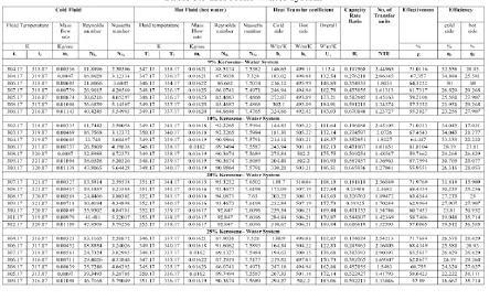
5.1.1 Effect Of NRe (Cold) On Efficiency % (Cold) 5.1.1.1 Kerosene – Water System
Cold side efficiency Vs Reynold Number(cold)
10 20 30 40 50
10 20 30 40 50
Reynolds Number(cold)
C
ol
d
si
de
e
ffi
ci
en
cy
, %
9% keros ene10% keros ene
20% keros ene 25% K eros ene
From the above graph it can be observed that, as NRe (cold) increases the efficiency (cold) decreases. The graph also
shows that as the composition of kerosene increases the efficiency of cold side increases and then decreases gradually for same flow rate of cold fluid.
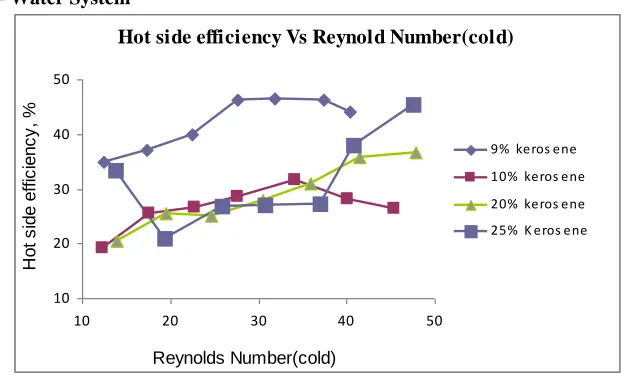
5.1.2 Acetic acid-water System
Cold side efficiency Vs Reynold Number(cold)
10 20 30 40 50 60 70 80
10 15 20 25 30 35 40
Reynolds Number(cold)
C
o
ld
s
id
e
e
ff
ic
ie
n
c
y
,
% 9% Acetic Acid
10% Acetic Acid 20% Acetic Acid 25% Acetic Acid
Fig. 5.2 Effect of cold side flow rate and composition on ηc of acetic acid-water system
It can be observed that, as flow rate of cold fluid increases the efficiency of cold side decreases. The graph also shows that as the composition of acetic acid increases the efficiency decreases for same flow rate of cold fluid. Maximum cold side efficiency is seen for 25% acetic acid -water system
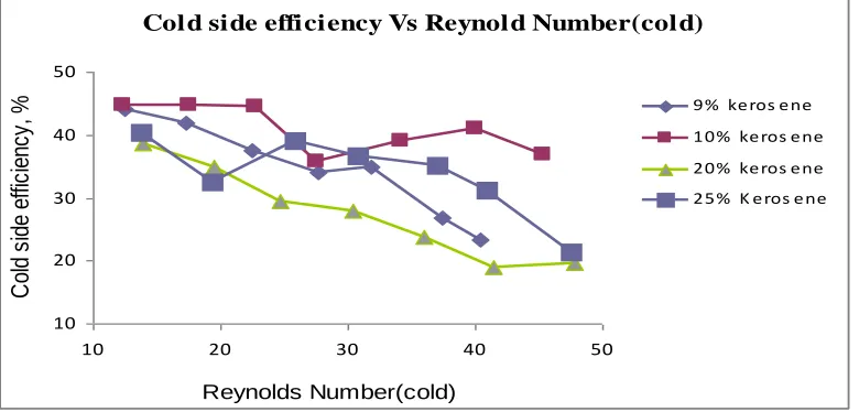
5.1.2 Effect of NRe (Cold) On Hot Side Efficiency (%) 5.1.2.1 Kerosene – Water System
Hot side efficiency Vs Reynold Number(cold)
10 20 30 40 50
10 20 30 40 50
Reynolds Number(cold)
H
o
t
s
id
e
e
ff
ic
ie
n
c
y
,
%
9% keros ene
10% keros ene
20% keros ene
25% K eros ene
Fig. 5.3 Effect of cold side flow rate and composition on ηh of kerosene-water system
From the graph Reynolds number of cold fluid Vs Hot side efficiency it can be observed that, as flow rate of cold fluid increases the efficiency of hot side gradually increases. When the flow rate on cold side is increased, heat transfer from hot to cold side is also increased. As the composition of kerosene increases from 9 % to 25 %, the efficiency of hot side decreases gradually for same flow rate of cold fluid.
Hot si de effi ci ency Vs Reynol d Number(col d)
0 10 20 30 40 50 60
10 15 20 25 30 35 40
Reynolds Number(cold)
H
ot
s
id
e
ef
fic
ie
nc
y,
% 9% Ace tic Acid
10% Ace tic Acid 20% Ace tic Acid 25% Ace tic Acid
Fig. 5.4 Effect of cold side flow rate and composition on ηh of acetic acid-water system
From the graph it can be observed that, as flow rate of cold fluid increases the efficiency of hot side gradually increases. When the flow rate on cold side is increased, heat transfer from hot to cold side is also increased. As the composition of acetic acid increases, the efficiency of hot side decreases for same flow rate of cold fluid.
5.2 CO-CURRENT FLOW PATTERN
5.2.1 Effect of NRe (Cold) On Cold Side Efficiency (%)
5.2.1.1 Kerosene – Water System
Cold side efficiency Vs Reynold Number(cold)
10 15 20 25 30 35 40
10 20 30 40 50
Reynolds Number(cold)
C
o
ld
s
id
e
e
ff
ic
ie
n
c
y
,
%
9% keros ene 10% keros ene 20% keros ene 25% K eros ene
Fig. 5.5 Effect of cold side flow rate and composition on ηc of kerosene-water system
From the above graph it can be observed that, as NRe (cold) increases the efficiency (cold) decreases. The graph also
shows that as the composition of kerosene increases the efficiency of cold side decreases gradually for same flow rate of cold fluid.
5.2.1.2 Acetic Acid – Water System
Cold side efficiency Vs Reynold Number(cold)
10 20 30 40 50
10 15 20 25 30 35 40
Reynolds Number(cold)
C
ol
d
si
de
e
ffi
ci
en
cy
, %
9% Ace tic Acid 10% Ace tic Acid 20% Ace tic Acid 25% Ace tic Acid
The graph shows that, as NRe (cold) increases the cold side efficiency decreases. As flow rate of cold side is
increased the cold side efficiency decreases. The graph also shows that as the composition of acetic acid increases the efficiency of cold side increases gradually, for the same flow rate of cold fluid.
5.2.2 Effect of NRe (Cold) On Hot Side Efficiency (%) 5.2.2.1 Kerosene – Water System
Hot side efficiency Vs Reynold Number(cold)
10 15 20 25 30 35 40
10 20 30 40 50
Reynolds Number(cold)
H
o
t
s
id
e
e
ff
ic
ie
n
c
y
,
%
9% keros ene
10% keros ene
20% keros ene
25% K eros ene
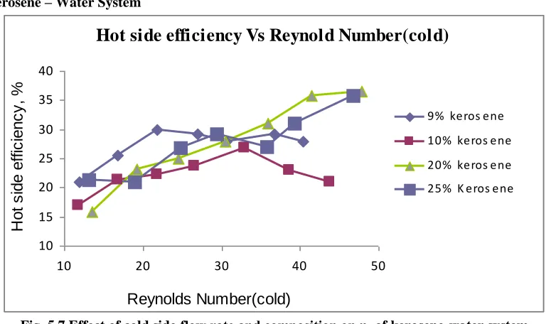
Fig. 5.7 Effect of cold side flow rate and composition on ηh of kerosene-water system
From the graph Reynolds number of cold fluid Vs Hot side efficiency it can be observed that, as flow rate of cold fluid increases the efficiency of hot side gradually increases. When the flow rate on cold side is increased, heat transfer from hot to cold side is also increased. As the composition of kerosene increases, the efficiency of hot side decreases at first and later it increases gradually for same flow rate of cold fluid.
5.2.2.2 Acetic Acid – Water System
Hot side efficiency Vs Reynold Number(cold)
0 5 10 15 20 25 30 35
10 15 20 25 30 35 40 Reynolds Number(cold)
H
o
t
s
id
e
e
ff
ic
ie
n
c
y
,
%
9% Acetic Acid 10% Acetic Acid 20% Acetic Acid 25% Acetic Acid
Fig. 5.8 Effect of cold side flow rate and composition on ηh of acetic acid-water system
V. CONCLUSION
Experiments were conducted on a Plate type heat exchanger with different flow rates and compositions of cold side fluid in both co-current and counter-current flow pattern. The effect of these parameters on heat transfer coefficient, efficiency and effectiveness were studied and comparison was made between co-current and counter-current flow operation.
It was found that as the flow rate of cold fluid increases, Reynolds number increases thereby increasing the cold side heat transfer coefficient. Consequently the overall heat transfer coefficient also increases with increase in flow rate of cold fluid for both counter-current and co-current flow pattern. The graphs also show that as the composition of cold fluid increases the NNu number decreases gradually for immiscible system, and increases for
miscible systems. Therefore the cold side heat transfer coefficient and overall heat transfer coefficient decreases for immiscible systems and increases for miscible systems.
For both counter-current and co-current flow pattern as NRe (cold) increased the NNu (hot) decreased
thereby, decreasing the heat transfer coefficient of the hot side. As the flow rate on cold side increased the heat transfer coefficient on hot side (hh) decreased thereby decreasing the overall heat transfer coefficient but as the
composition of cold fluid increases the heat transfer coefficient of hot side increases for the same flow rate of cold fluid
It was observed that the cold side efficiency and hot side efficiency for counter flow pattern is greater than the co-current flow pattern
From the results and discussion it can be concluded that, as flow rate of cold fluid increased the effectiveness gradually decreased. As the composition of cold fluid increased from 9% to 25%, the effectiveness of exchanger increased for immiscible systems and decreased for miscible systems for same flow rate of cold fluid for both counter current and co-current flow pattern.
Based on the overall results and discussion it was found that the overall heat transfer coefficient, hot side efficiency ,cold side efficiency and effectiveness was greater for counter current flow pattern when compared to co-current flow pattern.
Therefore it can be concluded that the counter-current flow pattern was efficient and feasible compared to co-current flow pattern irrespective of the type of cold fluid used.
APPENDIX I
MODEL CALCULATION Counter-Current Flow Pattern
Average temperature of cold fluid =
2
2 1
t
t
=
2
17
.
323
17
.
304
= 313.67 K
Average temperature of hot fluid =
2
2
1
T
T
=
2
17
.
332
17
.
347
= 339.67K
Logarithmic mean temperature difference =
1 1
2 2
1 1 2 2
ln
t
T
t
T
t
T
t
T
=
332
.
17
323
.
17
17
.
304
17
.
347
ln
17
.
323
17
.
332
17
.
304
17
.
347
= 21.739
Mass flow rate of cold fluid mc = Volumetric flow rate of cold fluid x Density
= (1 x 10^-3 x973.9417) / (60) Kg/sec = 0.016123 Kg/sec
Mass velocity of cold fluid = Mass flow rate / Flow area
= 0.0033567 /0.0045 = 0.74593 Kg/m2sec
Mass velocity of hot fluid = Mass flow rate / Flow area = 0.016123 / 0.0045 = 3.582888 Kg/m2sec Dimensionless numbers for cold fluid,
Reynolds number NRe =
V
D
e =
000599
.
0
74593
.
0
01
.
0
x
= 12.455Prandtl number NPr =
k
c
p
=
588332
.
0
000599
.
0
857
.
3995
x
= 4.067Nusselt number NNu =
4 . 0 Pr 65 . 0 Re28
.
0
N
N
=
0
.
28
12
.
455
0.654
.
067
0.4=2.52871. Dimensionless number for hot fluid,
Reynolds number NRe =
V
D
e =
000422
.
0
016123
.
0
01
.
0
x
= 85.46826Prandtl number NPr =
k
c
p
=
659672
.
0
000422
.
0
033
.
4194
x
= 2.683293Nusselt number NNu =
4 . 0 Pr 65 . 0 Re28
.
0
N
N
=
0
.
28
85
.
46826
0.652
.
6832
0.4= 7.486838
Cold side heat transfer coefficient hc = (NNu x k) / (De)
= (2.528571 x 0.588332) / (0.01) = 148.764 W/m2K
Hot side heat transfer coefficient hh = (NNu x k) / (De)
= (7.486838 x 0.659672) / (0.01) = 493.8858 W/m2K
Overall heat transfer coefficient
=
8858
.
493
1
273
02
.
0
764
.
148
1
1
= 113.3777 W/m2K
Capacity rate ratio = Cmin / Cmax
pc c
xc
m
C
min
= 0.0033567 x 3995.857 = 13.4129ph h
xc
m
C
max
= 0.016123 x 4194.033 = 67.6203 Capacity rate ratio = 13.4129 / 67.6203 = 0.1984Number of transfer units
min
C
xA
U
NTU
o= (113.3777 x 0.2925) / (13.4129) = 2.47244
Cold side efficiency
max
T
x
xc
m
T
x
xc
m
pc c pc c c
=
13
.
4129
43
19
4129
.
13
x
x
= 0.44186 = 44.186%
Hot side efficiency
max
T
x
xc
m
T
x
xc
m
ph h ph h h
=
67
.
6203
43
15
6203
.
67
x
x
= 0.3488 = 34.88
Effectiveness % =
1
NTU
x
100
NTU
=
100
47244
.
2
1
47244
.
2
x
= 71.202 %APPENDIX II
MODEL CALCULATION Co-Current Flow Pattern
Average temperature of cold fluid =
2
2 1t
t
=
2
17
.
318
17
.
304
= 311.17 K
Average temperature of hot fluid =
2
2 1T
T
=
2
17
.
338
17
.
347
= 342.67 K
Logarithmic mean temperature difference =
1 1
=
338
.
17
304
.
17
17
.
318
17
.
347
ln
)
17
.
304
17
.
338
17
.
318
17
.
347
= 31.433Mass flow rate of cold fluid mc = Volumetric flow rate of cold fluid x Density
= (12.5 x 10^-3 x 967.8842) / (60 x 60) Kg/sec = 0.003361 Kg/sec
Mass flow rate of hot fluid mh = Volumetric flow rate of hot fluid x Density
= (1 x 10^-3 x 972.4119) / (60) Kg/sec = 0.016207 Kg/sec
Mass velocity of cold fluid = Mass flow rate / Flow area = 0.003361 / 0.0045 Kg/m2sec = 0.74689 Kg/m2sec
Mass velocity of hot fluid = Mass flow rate / Flow area
= 0.016207 / 0.0045 Kg/m2sec = 3.60156 Kg/m2sec
Dimensionless numbers for cold fluid,
Reynolds number NRe =
V
D
e =
000628
.
0
003361
.
0
01
.
0
x
= 11.8895Prandtl number NPr =
k
c
p
=
585352
.
0
000628
.
0
66
.
3993
x
= 4.28556
Nusselt number NNu =
4 . 0 Pr 65 . 0 Re28
.
0
N
N
=
0
.
28
11
.
8895
0.654
.
2856
0.4= 2.50506
Dimensionless number for hot fluid,
Reynolds number NRe =
V
D
e =
000407
.
0
016207
010
.
0
x
= 88.51743Prandtl number NPr =
k
c
p
=
662113
.
0
000407
.
0
917
.
4195
x
= 2.5784Nusselt number NNu =
4 . 0 Pr 65 . 0 Re28
.
0
N
N
=
0
.
28
88
.
51743
0.652
.
5784
0.4= 7.5382
Cold side heat transfer coefficient hc = (NNu x k) / (De)
Hot side heat transfer coefficient hh = (NNu x k) / (De)
= (7.5382 x 0.662113) / (0.01) = 499.114 W/m2K
Overall heat transfer coefficient
h c o
h
k
x
h
U
1
1
1
=114
.
499
1
273
2
^
10
6344
.
146
1
1
= 112.4038 W/m2K
Capacity rate ratio = Cmin / Cmax
pc c
xc
m
C
min
= 0.0033361 x 3993.663 = 13.42154ph h
xc
m
C
max
= 0.016207 x 4195.917 = 68.0027Capacity rate ratio = 13.42154/ 68.0027
= 0.1974
Number of transfer units
min
C
xA
U
NTU
o= (112.4038 x 0.2925) / (13.4215)
= 2.449654
Cold side efficiency
max
T
x
xc
m
T
x
xc
m
pc c pc c c
=
13
.
42154
43
14
42154
.
13
x
x
= 0.3255814 = 32.558 %
Hot side efficiency
max
T
x
xc
m
T
x
xc
m
ph h ph h h
=
68
.
0027
43
9
0027
.
68
x
x
= 0.2093 =20.93 %
Effectiveness % =
NTU
NTU
1
x 100=
1
2
.
44967
4497
.
2
x 100 = 71.011 %REFERENCES
[1]. Bipan Bansal, Hans Müller-Steinhagen, Xiao Dong Chen. (2000). „Performance of plate heat exchangers during calcium sulphate
fouling — investigation with an in-line filter’. Chemical Engineering and Processing, Vol. 39, pp 507-519
[2]. Garcıa-Cascales J.R, Vera-Garcıa F., Corberan-Salvador J.M., J.Gonzalvez-Macia. (2007). „Assessment of boiling and condensation heat transfer correlations in the modelling of plate heat exchangers‟. International Journal of Refrigeration. Vol.30, pp 1029 – 1041.
[3]. Jameel Ur Rehman Khan ; Syed M. Zubair. , (2004) „A Risk-Based Performance Analysis of Plate-andFrame Heat Exchangers Subject
to Fouling: Economics of Heat Exchanger Cleaning’. Heat transfer engineering. Volume 25 , pages 87 - 100
[5]. Jorge A.W. Gut, Jose M. Pinto. (2004) . „Optimal configuration design for plate heat exchangers’. International Journal of Heat and Mass Transfer. Vol.47, pp 4833–4848.
[6]. Kevin M. Lunsford,(1996). “Advantages of Brazed Heat Exchangers in the Gas Processing Industry”. Proceedings of the Seventy-Fifth GPA Annual Convention. Tulsa, OK: Gas Processors Association, pp 218-226.
[7]. Lamb B. R..(1982). ‘Plate Heat Exchangers - A Low-Cost Route To Heat Recovery’. Heat Recovery Systems Vol. 2. pp. 247-255,
[8]. Longo G.A., Gasparella A.. (2007). „ Refrigerant R134a vaporisation heat transfer and pressure drop inside a small brazed plate heat exchanger‟. International Journal of Refrigeration. Vol. 30, pp 821 – 830.
[9]. McNeill,V.F., Colton,C.K.,. „Theory for Performance of the Flat Plate Heat Exchanger‟
[10]. Merheb B. , Nassar G. Nongaillard B., Delaplace G., Leuliet J.C.(2007) „Design and performance of a low-frequency non-intrusive acoustic technique for monitoring fouling in plate heat exchangers‟. Journal of Food Engineering. Vol. 82, pp 518–527.
[11]. Olaf Strelow. (2000). „A general calculation method for plate heat exchangers‟.
International Journal of Thermal Sciences, Vol. 39, pp 645-658.
[12]. Picon-Nunez M. And Martinez-Rodriguez G. And Lopez-Robles J. L. (2006). “Alternative Design Approach for Multipass and Multi-Stream Plate Heat Exchangers for Use in Heat Recovery Systems”. Heat Transfer Engineering, Vol. 27, pp 12–21.
[13]. Ribeiro C.P. Jr., Cano Andrade M.H.. (2002). „An algorithm for steady-state simulation of plate heat exchangers‟. Journal of Food Engineering. Vol. 53, pp 59–66.
[14]. Saman W.Y and Alizadeh S. (2001). ‘Modelling and performance analysis of a cross-flow type plate heat exchanger for
dehumidification/cooling’. Solar Energy. Vol. 70, pp 361-372.
[15]. Stamatiou E. and Kawaji M. (2003). “Heat Transfer Characteristics of Melting Ice Slurries in Compact Plate Heat Exchangers”. 21st IIR International Congress of Refrigeration, August 17-22. USA.
[16]. Warnakulasuriya F.S.K. and Worek W.M. (2008). „Heat transfer and pressure drop properties of high viscous solutions in plate heat
exchangers’. International Journal of Heat and Mass Transfer. Vol.51, pp 52-67.