Abstract—Due to government regulations and policies aimed at improving fuel economy and reducing emissions, it is increasingly important to achieve control over transient behavior and meet performance objectives over the life of the vehicle. This requires the development of high performance and robust power train controllers. The performance objectives are often conflicting, or at best interrelated. Controlling engine torque is one way to potentially meet these performance requirements. Spark ignition engine is a combustion engine that operates with a very wide operating point. Each point of engine operation provides different properties to each other, so that the control treatment to be given varies a great deal. This problem led to a single controller design becomes very difficult to be realized. In this research, a new design method of fuzzy robust control proposed to provide an alternative solution to build an integrated-control that can anticipate a system that works on a wide operating point and have different characters for each operating point. From the simulation results, it can be concluded that the design of robust fuzzy controller can be used simultaneously for several operating point without having to redesign the controller.
Index Terms—Spark ignition engine, engine torque, robust fuzzy control.
I. INTRODUCTION
Over the last three decades there has been a dramatic evolution in spark ignition engine control systems, largely driven by government regulations and policies aimed at improving fuel economy and reducing emissions. It is increasingly important to achieve control over transient behavior and meet performance objectives over the life of the vehicle. This requires the development of high performance and robust power train controllers. The performance objectives are often conflicting, or at best interrelated. Due to this reasons controlling of automotive engines is needed. Control of automotive engines focuses on a variety of problems, including control of idle speed, spark timing, air-fuel ratio, and engine torque. Various studies have been done to these efforts, some of which focus on controlling the engine speed and manifold pressure [3][4][11][17]. The problem is controlling the engine speed and manifold pressure has not been able to provide solutions to the needs of
Manuscript received June 24, 2011.
Aris Triwiyatno is with the Department of Electrical Engineering, Diponegoro University, Semarang, Indonesia (e-mail: aristriwiyatno@ yahoo.com).
Mohammad Nuh is with the Department of Electrical Engineering, Sepuluh Nopember Institute of Technology, Surabaya, Indonesia.
Ari Santoso is with the Department of Electrical Engineering, Sepuluh Nopember Institute of Technology, Surabaya, Indonesia.
I Nyoman Sutantra is with the Department of Mechanical Engineering, Sepuluh Nopember Institute of Technology, Surabaya, Indonesia.
large torque which at times appear more responsive. Another approach that proved more effective is by controlling engine torque [13][14][15]. By controlling engine torque automatically increases vehicle performance, improving fuel economy and reducing emissions. This happens because the maximum engine torque can be achieved only by doing perfect combustion of fuel in the combustion cylinders, meaning to maintain perfect combustion of fuel usage to be effective and efficient.
This paper focuses in particular on spark ignition engine torque control. Spark ignition engine is a combustion engine that operates with a very wide operating point. Each point of engine operation provides different properties to each other, so that the control treatment to be given varies a great deal. This problem led to a single controller design becomes very difficult to be realized, as been proposed in the last studies by robust control techniques [2][4][11], optimal control techniques [13][15], and optimal-fuzzy control technique [17]. In these studies, some conditions of engine operation can be controlled well with appropriate process control, but in other conditions, without redesigned the controller, the system becomes unstable or not good enough to meet its performance requirements. In this research, a new design method of fuzzy robust control proposed to provide an alternative solution to build an integrated-control that can anticipate a system that works on a wide operating point and have different characters for each operating point. The solution offered is to create multiple soft-switching with fuzzy reasoning for the optimal solution control at every operating point. Optimal solution control at each operating point was designed by using linear quadratic integral optimal control tracking problem.
As an implementation, by using approximation of AFR and ignition time is left on the standard setting that ideally yield maximum engine torque, i.e. at 14.7 AFR and the spark advance to 15 degree MBT, the throttle opening commanded by the driver will be corrected with secondary throttle [15] that guarantees engine torque output will follow the desired engine torque input. In this case, spark ignition engine with automatic transmission is used to meet a good performance under this controller design.
II. SPARK IGNITION ENGINE WITH AUTOMATIC TRANSMISSION
In general, block diagram of the spark ignition engine with transmission control unit depicted in Fig. 1. In this research, the model was a 4-step gear transmission [1].
Engine receives input of the throttle opening provided by the driver. The resulting spin machine connected to the impeller of torque converter that is coupled also with the transmission control unit.
Engine Torque Control of Spark Ignition Engine
Using Robust Fuzzy Logic Control
i e e
eiN T T
I & = − (1) where
e
N = engine speed
ei
I = engine + impeller moment of inertia
e
T = f1(throttle, Ne) = engine torque i
T = impeller torque
Input-output characteristics of the torque converter can be expressed with the functions of engine speed and turbine speed.
i TQ t
e i
T R T
K N T
=
= 2
) / (
(2)
where
K = f2(Nin/Ne)
= capacity of K-factor
Nin = turbine (torque converter output) speed
= transmission input speed Tt = turbine torque
RTQ = torque ratio
= f3(Nin/Ne)
Transmission model is expressed as static gear ratios, assumed to have only a small time shift, so that it can be ignored (in fact a matter of this time shift will cause problems robustness).
out TR in
in TR out
TR
N R N
T R T
gear f R
= =
= 4( )
(3)
where
Tin, Tout = transmission input and output torque
Nin, Nout = transmission input and output speed
RTR = transmission ratio
Fig. 1. Block diagram of spark ignition engine with transmission control unit [1]
Vehicle dynamics in this model is influenced by the final drive, inertia, and dynamically varying load.
) ( out load
fd w
vN R T T
I & = − (4) where
Iv = vehicle inertia
Nw = wheel speed
Rfd = final drive ratio
Tload = load torque
= f5(Nw)
Load torque includes road load and brake torque. Road load is the summation of frictional and aerodynamic losses.
) )(
sgn( 2
2
0 load brake
load
load mph R R mph T
T = + + (5)
where
Tload = load torque
Rload0, Rload2 = friction and aerodynamic drag
coefficients
Tbrake = brake torque
mph = vehicle linear velocity
Fig. 2 provides an illustration of the shift gear ratio schedule. Transmission gear ratio is given in Table I.
Fig. 2. Gear Shift Schedule [1]
TABLEI:GEAR RATIOS [1]
Fig. 3. Mapping Pedal Position and Engine Speed with Engine Torque Command for Sporty Vehicle Feel [13]
Fig. 4. Mapping Pedal Position and Engine Speed with Engine Torque Command for Economical Vehicle Feel [13]
In this research, engine torque control regulation conducted only by controlling throttle plate angle with secondary throttle [15]. AFR and ignition time is left on the standard setting that ideally yield maximum engine torque, i.e. at 14.7 AFR and the spark advance to 15 degree MBT.
IV. OPTIMAL CONTROL: LINEAR QUADRATIC INTEGRAL TRACKING PROBLEM
Integral action is used in classical control to eliminate steady state errors when tracking constant signals. It can be generated in a LQ setting by considering the integral of the output error as an extra set of state variables.
Consider a state equation of dynamic system as follow:
) ( ) ( ) ( ) ( ) ( t Cx t y t Bu t Ax t x = + = & (6)
The integral of the tracking error is generated by the following differential equation:
) ( ) ( ) ( ) ( t Cx t r t y t r w − = − = & (7)
Define an augmented state error ⎥
⎦ ⎤ ⎢ ⎣ ⎡ = w x x ~
ˆ then the augmented error state equation is:
{ u B x C A t x B A ~ 0 ˆ 0 0 ) ( ˆ ˆ ˆ ⎥ ⎦ ⎤ ⎢ ⎣ ⎡ + ⎥ ⎦ ⎤ ⎢ ⎣ ⎡ − = 43 42 1
& (8)
A suitable performance index would be:
∫
+ ≥ >= ~ 0 0 , 0 , ~ ~ ˆ
ˆ Qx u Ru Q R x
J T T
(9)
The optimal control law is as follow: x K
u~=− ˆ (10) where
[
x w]
T K K S B R K= −1ˆ =
(11) S is the solution to the ARE:
Q S B R B S A S S
AT + − T +
= ˆ ˆ ˆ − ˆ
0 1
(12) Using the definitions for xˆ and u~, we have:
u w K x K
u=− x~− w + (13) but ~x=x−x, therefore:
u w K x x K
u=− x( − )− w + (14) We have seen before that u CA1B 1r
]
[ − −
−
= and
r B CA B A
x 1 1 1
]
[ − −
−
= . The control law is then: r K w K x K
u=− x − w + r (15)
where 1 1 1 ] ][ [ − − − −
= K A B I CA B
Kr x (16)
V. FUZZY LOGIC CONTROLLER AS MULTIPLE SOFT SWITCHING
Fuzzy logic controller is one of the controllers based on if-then rules that can be used for decision making as the human mind. At this research, Sugeno fuzzy inference mechanism is used as soft-switching of optimal control gain data base. The purpose of soft-switching is to select the most appropriate optimal control gain based on the approximate operating point of the system. The inputs of fuzzy control system are estimated information of operating point and state of the system. The outputs of fuzzy control system are the control action signals.
Sugeno is that the Sugeno output membership functions are either linear or constant.
A typical rule in a Sugeno fuzzy model has the form as: If Input 1 = x and Input 2 = y,
then Output is z = ax + by + c (17) For a zero-order Sugeno model, the output level z is a constant (a = b = 0).
The output level zi of each rule is weighted by the firing
strength wi of the rule. For example, for an AND rule with
Input 1 = x and Input 2 = y, the firing strength is:
wi = AndMethod (F1(x), F2(y)) (18)
where F1,2(.) are the membership functions for Inputs 1 and
Inputs 2. The final output of the system is the weighted average of all rule outputs, computed as:
∑
∑
= =
= N
i i N
i i i
w z w Output Final
1 1
(19)
A Sugeno rule operates as shown in the Fig. 5.
Fig. 5. Sugeno Rule Diagram
Using Eq. 15, linear equation of the output of Sugeno fuzzy inference system as Eq. 19 can be modified as follow:
(
)
∑
∑
= =
+ − − =
= N
i i N
i
i r i w i x i
i
w
r K w K x K w u Output Final
1
1 (20)
where
x : state of the system.
w : error between output and reference signal. r : reference signal.
As being a soft-switching, the inputs of fuzzy inference system must be coupled with estimated operating point information. But because it only serves as conditional inputs, these inputs cannot be involved to the calculation of output as in Eq. 20, so that Eq. 20 can be modified as follows:
(
)
∑
∑
= =
+ − −
= N
i i N
i
i r i w i x i c i
i
w
r K w K x K c K w u
1 1
(21)
where
c = operating point information signals. Kc =
[
k1 L kn]
= gain of information signals, with every ki = 0, as n is amount of
operating point information signals.
As a switching mechanism, the rules of the fuzzy inference system are redesigned as one of example as follows: Rule-i:
If (Cond1 is ThVLow) and (Cond2 is G1) and (Ref is EngDes) and (IntErr is dotw) and (State1 is x1) and (State2 is x2) then
[
]
[
]
ef R K IntErr K
State State K Cond Cond
K z
i r i
w
T i
x T i
c i
. .
2 1
2 1
+ −
− =
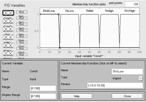
(22) Fig. 6 shows input-output global design. Fig. 7 and Fig. 8 show example of membership functions of input and output fuzzy logic controller to be used.
Fig. 6. Input-output design
Fig. 8. Membership functions of the optimal control gain TH1
VI. SIMULATION AND ANALYSIS
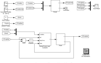
Simulations performed with Matlab Simulink as shown in Fig. 9 and Fig. 10. The simulation results with some operating point are shown in Fig. 11, Fig. 12, Fig. 13, and Fig.
14, including uncontrolled and controlled by fuzzy control responds.
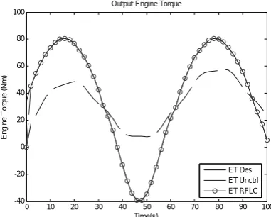
Fig. 11 simulated using operating condition throttle opening about 10 degrees and first gear application. Fig. 12 simulated using throttle opening about 10 degrees and second gear application. It can be shown that there are different characteristics of the system with the addition of gear position. By providing such a fuzzy controller applications that have been designed previously, we see that the system will work better by performing tracking in accordance with the desired engine torque based on throttle input opening (using the mapping economical vehicle feel).
Similarly, by changing the throttle opening wide enough, with the same gear position, as shown in Fig. 13 and Fig. 14, where Fig. 13 shows the simulation with the input throttle opening of about 30 degrees and the third gear position, and Fig. 14 shows the simulation with the input throttle opening amounting to about 50 degrees and the third gear position, we see that the system will work better too by performing tracking in accordance with the desired engine torque based on throttle input opening (using the mapping economical vehicle feel).
Throttle
Terminator Secondary Throttle
(0 - 100 %)
Condition Ref Intgrl Error State
U
Robust Fuzzy Logic Controller
u y
x
Plant1
u y
x
Plant 1
s Integrator [Gear]
[Throttle2nd]
[Throttle] [TEngUnctrl]
[TEngOpt] [T EngDes]
4 Gear Position
[T EngOpt]
[Gear]
[Throttle2nd] [Throttle]
[TEngDes]
[T EngDes] [TEngUnctrl]
[Throttle]
Eng Torque
Double Click for initialitation
TEngDes
Desired Torque
Add1
Fig. 9. Simulation main model using Matlab Simulink Toolbox
1 U Robust Fuzzy Logic
Controller -1
-1 4 State
3 Intgrl Error
2 Ref
1 Condition
0 10 20 30 40 50 60 70 80 90 100 -40
-20 0 20 40 60 80 100
Output Engine Torque
Time(s)
E
n
gi
ne
T
o
rqu
e
(N
m
)
ET Des ET Unctrl ET RFLC
Fig. 11. Simulation result with engine operating condition: throttle opening about 10 degrees and first gear application
0 10 20 30 40 50 60 70 80 90 100
-40 -20 0 20 40 60 80 100
Output Engine Torque
Time(s)
E
ngi
ne
T
or
que
(
N
m
)
ET Des ET Unctrl ET RFLC
Fig. 12. Simulation result with engine operating condition: throttle opening about 10 degrees and second gear application
0 10 20 30 40 50 60 70 80 90 100
0 20 40 60 80 100 120 140 160 180 200
Output Engine Torque
Time(s)
E
ngi
ne
T
or
que
(
N
m
)
ET Des ET Unctrl ET RFLC
Fig. 13. Simulation result with engine operating condition: throttle opening about 30 degrees and third gear application
0 10 20 30 40 50 60 70 80 90 100
0 50 100 150 200 250 300
Output Engine Torque
Time(s)
E
ng
ine T
or
q
ue (
N
m
)
ET Des ET Unctrl ET RFLC
Fig. 14. Simulation result with engine operating condition: throttle opening about 50 degrees and third gear application
VI. CONCLUSION
From the simulation results, it can be summarized that by using fuzzy controller design as above, the controller operates very well for a wide operating point with the character differences are quite striking. This will give a controller design effectiveness and impact indirectly plays an important role in improving engine performance.
It can be concluded too that the use of knowledge-based control system applications will be very beneficial to overcome control problems with performance index contradictory as torque settings on spark ignition engines. It's just to complete this research needs to be clarification of the rule base according to the manufacturer's standards and drive the action that is given not only opening the throttle valve and secondary throttle, but also includes the arrangement of air to fuel ratio and ignition time. Thus the fuzzy rules have the discretion to reduce the use excess fuel to get the engine torque as close as possible to the desired engine torque.
[1] Using Simulink and Stateflow in Automotive Applications, The MathWorks Inc.
[2] Abate, M, et.al., “Application of Some New Tools to Robust Stability Analysis of Spark Ignition Engines: A Case Study”, IEEE Transactions on Control Systems Technology, Vol. 2, No. 1, March, 1994.
[3] Agung Nugroho, “Desain Kompensator Sistem Pengaturan Kecepatan pada Spark Ignition Engine dengan Menggunakan QFT”, Final Project, ITS, Surabaya, 2004.
[4] Agus Salim, “Desain Kompensator sebagai Kontrol Robust pada Sistem Pengapian Spark Ignition Engine”, Thesis, ITS, Surabaya, 2004.
[5] Bosch, Automotive Electric/Electronic System, Robert Bosch GmbH, Postfach 30 02 20 D-70442 Stuttgart, 1995.
[6] Blaich B., Schwarz H., Spark Ignition Engine, Engine Design and Operating Conditions, Fuel for SI Engine, Bosch, USA, 1995. [7] Braae, M and Rutherford D A, “Theoretical and Linguistic Aspects of
the Fuzzy Logic Controller”, Automatica, Vol. 15, 1979.
[8] Denton T, Automobile Electrical and Electronic System, Colchester Institute, Colchester, Essex, 1995.
[9] Fukami, S, Mizumoto M, and Tanaka K, “Some Considerations of Fuzzy Conditional Inference”, Fuzzy Sets Systems, Vol. 4, 1980, pp. 243-273.
[10] Harris, C.J., Moore C.G., and Brown M, “Intelligent Control: Aspect of Fuzzy Logic and Neural Nets”, World Scientific Series in Robotics and Automated Systems, Vol. 6, 1993.
[11] Irianto, “Analisis Sistem Pengaturan Kecepatan Spark Ignition Engine Menggunakan Kontrol Robust MIMO”, Thesis, ITS, Surabaya, 2005.
[12] Shahian, B, Hassul, M, Control System Design Using Matlab, Prentice-Hall Int. Inc.
[13] Heintz, N., Mews, M., Stier, G., Beaumont, A.J., and Noble, A.D. (2001), "An Approach to Torque-Based Engine Management Systems", SAE 2001-01-0269.
[14] Kolmanovsky, I., Druzhinina, M., and Sun, J., “Nonlinear Torque and Air-to-Fuel Ratio Controller for Direct Injection Stratified Charge Gasoline Engines”, Proceeding of AVEC 2000, 5th Int'l Symposium on Advanced Vehicle Control, Michigan, 2000.
[15] Lamberson, D.M., “Torque Management of Gasoline Engine”, Thesis Master, Mechanical Engineering, University of California at Berkeley, 2003.
[16] Sugeno, M., “Industrial applications of fuzzy control”, Elsevier Science Pub. Co., 1985.
[17] Triwiyatno A., “Engine Speed and Manifold Pressure of Spark Ignition Engine Control System Design using Optimal-Fuzzy Control”, Thesis, ITS, Surabaya, 2005.
Aris Triwiyatno, received the B.S. degree in electrical engineering from Sepuluh Nopember Institute of Technology, Surabaya, Indonesia, in 1998, and the M.T. degree in the same college in 2005. He has been a lecturer at the Department of Electrical Engineering, Diponegoro University, Semarang, Indonesia since 2000. His research interests are on the fuzzy systems including fuzzy control systems and fuzzy neural image processing.
He is currently as a student in Sepuluh Nopember Institute of Technology to pass his PhD degree.
Mohammad NUH, received the B.S. degree in
electrical engineering from Sepuluh Nopember Institute of Technology, Surabaya, Indonesia, in 1983, and the DEA and PhD degrees in Universite Science et Technique du Languedoc (USTL), Montpellier, France, in 1989 and 1992, respectively. He is currently a Professor with the Department of Electrical Engineering, Sepuluh Nopember Institute of Technology, Surabaya, Indonesia. His research interests are on digital signal processing including biomedical control engineering and fuzzy control system.
Ari Santoso, received the B.S. degree in electrical
engineering from Sepuluh Nopember Institute of Technology, Surabaya, Indonesia, in 1990, the DEA degree in Institut National Polytechnique de Grenoble (INPG), France, in 1996, and PhD degree in Universite Montpellier II, France, in 1999. He is currently a lecturer and researcher in Sepuluh Nopember Institute of Technology, Surabaya, Indonesia. His research interests are on artificial intelligent control and car engine control system.
I Nyoman Sutantra, received the B.S. degree in
![Fig. 2. Gear Shift Schedule [1]](https://thumb-us.123doks.com/thumbv2/123dok_us/1367264.1646350/2.595.318.531.325.498/fig-gear-shift-schedule.webp)
![Fig. 3. Mapping Pedal Position and Engine Speed with Engine Torque Command for Sporty Vehicle Feel [13]](https://thumb-us.123doks.com/thumbv2/123dok_us/1367264.1646350/3.595.64.272.260.417/mapping-position-engine-engine-torque-command-sporty-vehicle.webp)