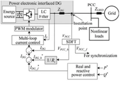
Development Of A VCM Based Harmonic Controlled Dg-Grid
Interfacing Converters
M.Siva Prasada Reddy
1, E.Narasimhulu
21
P.G.Student, Dept. of EEE, Rajeev Gandhi Memorial college of Engineering and Technology, Nandyal,
Andhra Pradesh, India
([email protected])
2
Asst.professor, Dept. of EEE, Rajeev Gandhi Memorial college of Engineering and Technology ,
Nandyal ,Andhra Pradesh,India
([email protected])
Abstract—Now a days the non-linear loads and power electronic based DG systems involvement is increased and these are may introduce power quality issues to the distribution power systems. If we use DG grid interfacing converters properly and regularly then they will improve distribution system efficiency and power quality. This paper mainly discuses on the distribution system harmonic control through DG grid interfacing converters. There is two DG systems in general, one is current controlled DG and another one is voltage controlled DG. There is major previous works on harmonic compensation are done in current controlled DG .But hear a new harmonic control scheme using voltage controlled method is developed in this paper. This method is having more flexibility and similar compensation performance when compare to current controlled DG .This voltage controlled method provides direct voltage and frequency support to grid because of avoiding harmonic current tracking loop. This proposed systems simulated by using MATLAB/SIMULINK.
Index terms : Distributed Generation(DG), Circulating current, Distributed active power filter(APF),Power quality, Harmonic compensation.
I INTRODUCTION
VCM because of providing voltage and frequency support for loads[17]-[19].This VCM based v-f droop control will control the DG interfacing converters. Hear current controlled compensation is used for APF applications and cannot be implemented directly. In order to overcome this limitation a new VCM based harmonic control method is developed which is don’t having current loop and harmonic current reference.This paper starts with brief explanation of harmonic compensation based on CCM in Section II and VCM based harmonic compensation in Section III. The proposed method is more flexible and gives similar compensation when compare to CCM based compensation .The comparison between two methods is explained in section IV. At last the simulation results are provided in section V. Mainly harmonic compensation is focused on this paper and also proposed control method is extended to address other voltage quality problems [e.g voltage flicker and imbalance].
II. CCM-BASED COMPENSATION
Fig. 1.Compensation scheme for current-controlled DG
Before going to discuss proposed VCM based harmonic compensation ,the CCM based harmonic compensation is explained in this section. The selection of PCC voltage(point of common coupling) quality improvement using current controlled grid connected DG has been taken in [3]-[5].Generally this method uses to control the DG unit as shunt APF(active power filter),Because hear the DG unit absorbs harmonic currents of non-linear loads and leaves a better source current and PCC voltage with lower total harmonic distortion(THD).The best way to achieve this function is to control the DG as resistance APF(R-APF) [10],[12],[21],[22],where PCC voltage is measured and harmonic components are extracted to gives reference harmonic current of a DG( ∗=VPCC_h/Rh) .So DG unit acts as small resistance( )at harmonic frequencies.
Fig. 2. SDFT for fundamental and harmonic component extraction.
The reference harmonic current generation and the current tracking loop designed carefully because there is a chance to obtain conflicts between PCC voltage harmonics and the primary function of real power injection of a DG system. Traditionally the separation of harmonic and fundamental components of PCC voltage uses high or low pass filter in either the stationary or synchronous frame[13].This filtering introduces the magnitude and phase errors in the extracted signals which leads to inaccurate compensation performance. On the other hand ,it is need to avoid the high-order harmonic tracking due to limited current control bandwidth. The current tracking and inaccurate harmonic voltage extraction may increases these high order or even lead to system instability.So most significant low order harmonics in a system would be more appropriate[such as 5th,7th,11thharmonics ].
To extract the harmonics in selective manner ,resonant filters are used in[5].The resonant filters has fast change of phase angle around the resonant frequencies. As a result even small variation of resonant frequencies may introduce substantial phase errors in extracted signals. To extract the harmonics accurately we can use the sliding discrete fourier transform[SDFT][14].The SDFT for fundamental and harmonic component extraction is shown in figure 2.From the figure 2 SDFT having simple structure with sliding window[with N points] and can be realized easily in DSP for real-time implementation. The z-domain transfer function for theℎ harmonic can be described as
=
∗ (1)
Once the harmonic voltage is obtained ,the harmonic current reference can be produced by using designed harmonic resistance or frequency varying conductance .Hear the values of and will affects the compensation performance.Normally smaller will gives better compensation performance but it reduces the DG system stability.The available rating of DG also determines the value of in order to avoid problem with the primary function of power generation.The DG’s available rating can be realized through an adoptive control algorithm [4],[5],[8],[9] or by an integral ontroller[12].By adding the harmonic current reference and fundamental reference from power control loop,we
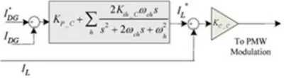
Fig. 3. Multiloop current tracking diagram.
Can get DG reference current. The multi loop current tracking diagram as shown in figure 3. From the controller diagram the currents ∗ and are DG reference and feedback currents.To achieve good fundamental and harmonic current tracking performance a current controller based on resonant controllers[at fundamental and harmonic frequencies of interest] can be used [15],[16].
( ) = _ + ∑ (2)
controller _ is also added in figure 3. At last it should be noted that the feeder impedence is small and DG unit is connected to grid through an LCL filter ,then voltage meadured at the installation point can very close to pcc voltage. Therefore remote PCC voltage measurement is not required for this compensation scheme.
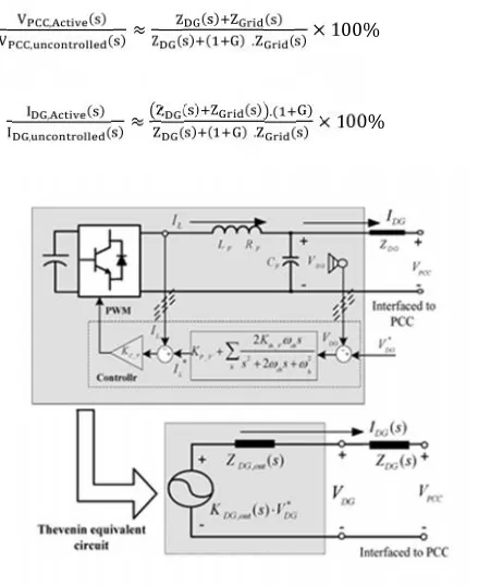
III. PROPOSED VCM-BASED COMPENSATION
CCM is mostly employed for grid connected DG inverters ,the voltage controlled DG can also adopted as discussed in [17]-[19]. If a DG system operated in islanding mode, the VCM will provide seamless operation and also provide necessary voltage and frequency support.
(A) Principle of Harmonic Compensation :
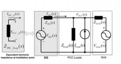
The equivalent circuit of single DG grid system as shown in figure 4.from the diagram DG unit represented as controlled voltage source with an output series impedence .The grid described as a voltage source
and grid impedence .
Fig. 4. Equivalent circuit of a single DG–grid system with VCM.
The PCC non-linear load is shown in the middle as a harmonic current source and passive loads. If the DG harmonic voltage( _ℎ)is controlled by using pcc harmonic voltage ( _ℎ)as
VDG_h(s) =−G · VPCC_h(s) (3)
The equivalent harmonic impedence of DG at installation point can be derived given below IDG_h = (VDG_h − VPCC_h)/ZDG_h
=−(1 +G)VPCC_h/ZDG_h
ZDG_h,eq=− VPCC_h/IDG_h=ZDG_h /(1 +G) (4)
where _ℎis the DG harmonic current and _ℎis the DG harmonic impedance. This equivalent impedance at harmonic frequencies is also shown in the left side of Fig. 4.
With G=0,system will be a standard voltage controlled DG without any active compensation. Hear harmonic current is shared automatically to the DG and grid side harmonic impedences.This is similar to current controlled method, where DG current is sinusoidal if the active power filtering function is not enabled.
Furthermore, it is known that the focus of v-f droop control of parallel DG systems is fundamental power flow. So DG current is like to have harmonic problems. The proposed method may also used to control the DG current with lower harmonics and better THD. If the DG harmonic current is attenuated properly with negative DG, the performance will be similar to conventional current controlled DG.
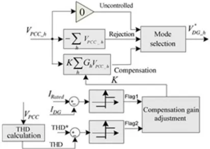
The value of G can be controlled with a range from -1 to ∞ for different compensation requirements or DG operation objectives. Select the practical limit of G tends to have over modulation problems and makes system unstable. At last it is important to note that G should not be less than–1 ,this will introduce capacitive equivalent impedence, which may be induce system resonance.
In this work G> 0is named as harmonic compensastion,G <0 is defined as harmonic rejection mode, G = 0 is named as uncontrolled mode.
Fig. 5. Proposed control strategy for voltage-controlled DG.
The proposed voltage controlled DG scheme is as shown in figure 5. From the figure 5 SDFT block will separates fundamental and harmonic components of PCC voltage. Hear fundamental voltage is useful for grid voltage synchronization and DG fundamental real and reactive power calculation. The harmonic component are used to generate the inverter reference harmonic voltage .From the control diagram of VCM the real and reactive power block will produce the fundamental reference of the DG voltage. While reference DG voltage is produced by the active harmonic control block .
The active harmonic control mechanism is as shown in figure 6. As earlier said, this control block can be operated in three modes. They are compensation, rejection, uncontrolled mode.The ‘Compensation gain adjustment‘ block is added to avoid overrating operation and possible conflict with primary function of real power control .By using adoptive controller [4] ,[5],[8],[9] or simple integral controller [12],this algorithm sets the value of K ,which will changes the effective gain is lower for high order harmonics. At last it will be noted that harmonic rejection mode = -1 is used for all the selected harmonics in this work.
B. Analysis of the Proposed Control Strategy :
From the fig.4, 5, 6
(s) + ( )/ ( )+ ( )/ ( )- ( )/ ( )= 0 (5)
1/ ( )=1/ ( )+1/ ( )+1/ ( ) (6)
Consider ( )is much higher than ( )and ( )and ( )≈ 0 at harmonic frequencies .If the DG harmonic voltage is controlled actively (harmonic compensation/rejection), then PCC harmonic voltage and DG harmonic current attenuation ratios when compared to uncontrolled mode can be obtained as shown in below.
, ( )
, ( )≈
( ) ( )
( ) ( ) . ( )× 100% (7)
, ( )
, ( )≈
( ) ( ) .( )
( ) ( ) . ( ) × 100% (8)
Fig. 7. Multiloop voltage control and its Thevenin equivalent circuit
Multiloop VCM is applied due to tracking of voltage reference properly. The total multiloop DG voltage control block is shown in figure 7.Here ,the parallel resonant controllers for fundamental and different harmonic components are used as outer voltage loop controller and inner proportional current control ( _ ) uses the LC filter inductor current as feedback.
The closed loop dynamic behavior of DG is evaluated by Thevenin equivalent circuit is shown in lower part of figure 7.This is expressed in
Where , ( )and , (s)are the equivalent DG output impedence and voltage tracking gain associated with the multiloop voltage control scheme and ∗ is reference DG voltage. From the figure 7 the , ( ) and
, (s)are derived as in
, (s) = ( ) ( ) ( )( ) __ ( ) ( )( ) ( ) ( ) _ (10)
, (s) = ( ) ( ) ( )(( ) _ ( ) ( )( )) ( ) _ (11)
where M(s) = 1/( s + RF ) and N(s) = 1/( s) are the transfer functions related to the LC filter parameters ( , , and are the filter inductance, inductor stray resistance, and filter capacitance, respectively).The transfer function of the outer loop voltage controller ( )is
( ) = _ + ∑ _ (12)
The accurate DG equivalent harmonic impedence at the PCC when dynamics of voltage controller are considered is given as
Z , =ZDG(s). ,, ( )( ) (13)
IV. COMPARISON BETWEEN VCM AND CCM
Both CCM and VCM can efficiently control the DG real and reactive power and compensate the pcc harmonic voltage. Following are the comparison between the two methods.
1) In without compensation mode, the ccm will pushes all harmonic currents to grid side automatically. So the PCC voltage is polluted due to harmonic voltage drops on the source impedence. But the voltage controlled DG can share the non linear load current with the source according to their respective impedences. So with the conventional control VCM leads to better PCC voltage compared to ccm
2) Let the DG system operating in intentional islanding mode, the VCM has the advantage of seam less control transition for operating mode. In contrast, the ccm has the difficulties in islanding operation,as it is difficult to provide voltage and frequency support in islanding mode.
V.SIMULATION RESULTS
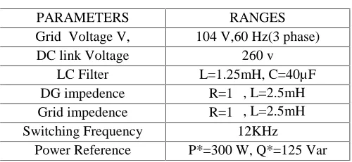
The proposed harmonic control strategies are verified are verified through Matlab/simulink. Hear both ccm and VCM are implemented for harmonic compensation. While in the simulation the non-linear load at the PCC is three phase diode rectifier with parallel connected capacitor(1000 µF) and resistor(25Ω) at the DC side. The system parameters used in simulation are listed in tableI.
TABLE I
PARAMETERS IN THE SIMULATION
PARAMETERS RANGES
Grid Voltage V, 104 V,60 Hz(3 phase)
DC link Voltage 260 v
LC Filter L=1.25mH, C=40µF
DG impedence R=1Ω, L=2.5mH
Grid impedence R=1Ω, L=2.5mH
Switching Frequency 12KHz
Power Reference P*=300 W, Q*=125 Var
1) CCM :
The current controlled interfacing inverter tested in simulation with 5thharmonics is compensated. The performance of current controlled DG without harmonic compensation is shown in figure 12
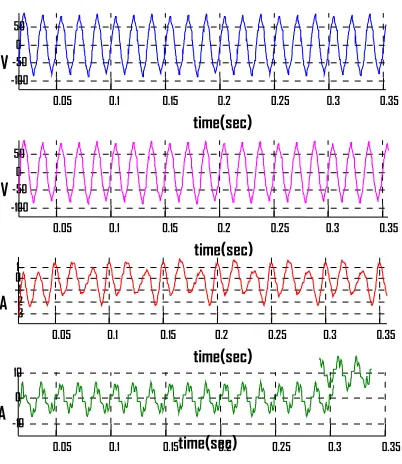
Fig. 12. Current-controlled method without harmonic compensation. (a) PCC phase voltage. (b) Grid current. (c) DG current 0.05 0.1 0.15 0.2 0.25 0.3 0.35
-50 0 50
V
time(sec)
0.05 0.1 0.15 0.2 0.25 0.3 0.35 -5
0 5
A
time(sec
0.05 0.1 0.15 0.2 0.25 0.3 0.35 -10
-5 0 5
A
time(sec)
(a)
(b)
From the figure the DG current has very little harmonic current and the grid supplies the non-linear load current. Therefore PCC voltage is polluted due to harmonic voltage drop on the grid impedence. The performance of CCM with harmonic compensation is shown in figure 13.
Fig. 13. CCM with harmonic compensation. (a) PCC phase voltage. (b) Grid current. (c) DG current.
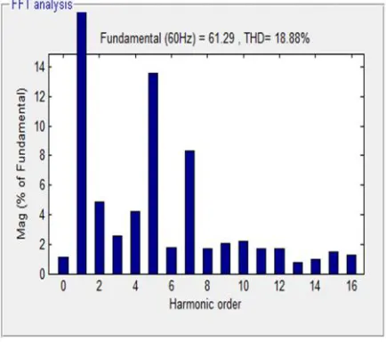
As expected that the low resistence at the selected harmonic frequencies, the DG unit absorbs most of the non-linear load currents and leaves improved pcc voltage, grid current as shown in the figure 13 (a),(b).The figure 14 and 15 represents the harmonic analysis of PCC voltage in ccm without and with harmonic compensation.
Fig 14: harmonic analysis of PCC voltage without compensation(CCM)
0.05 0.1 0.15 0.2 0.25 0.3 0.35
-50 0 50
V
time(sec)
0.05 0.1 0.15 0.2 0.25 0.3 0.35
-5 0 5
A
time(sec)
0.05 0.1 0.15 0.2 0.25 0.3 0.35
-10 -5 0 5
A
time(sec)
(a)
(b)
Fig 15: harmonic analysis of PCC voltage with compensation(CCM)
From the figures 14 and 15 ,The THD of the PCC voltage without compensation is 18.88 % and the harmonic distortion is reduced to 8.67 % by applying the current controlled harmonic compensation method.
2) VCM:
The voltage controlled DG and different operating modes are also tested in simulation, and the results shown in figures 16-18.
Fig. 16. VCM without compensation. (a) PCC phase voltage. (b) DG phase voltage. (c) Grid current. (d) DG current 0.05 0.1 0.15 0.2 0.25 0.3 0.35
-100 -50 0 50
V
time(sec)
0.05 0.1 0.15 0.2 0.25 0.3 0.35 -100
-50 0 50
V
time(sec)
0.05 0.1 0.15 0.2 0.25 0.3 0.35 -3
-2-1 0 1
A
time(sec)
0.05 0.1 0.15 0.2 0.25 0.3 0.35 -10
0 10
A
Fig. 17. VCM with harmonic compensation. (a) PCC phase voltage. (b) DG phase voltage. (c) Grid current. (d) DG current
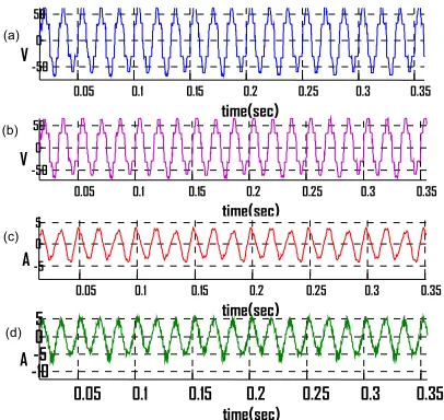
Fig. 18. VCM with harmonic rejection. (a) PCC phase voltage. (b) DG phase voltage. (c) Grid current. (d) DG current.
Figure 16 shows VCM without any harmonic compensation ,where the DG unit is controlled with pure sinusoidal voltage (see the fig.16(b)).In this mode, DG and grid share non-linear load current as we see from fig.16(c) and (d).Consequently, the PCC voltage is distorted due to non-linear load currents through the grid impedence.
The VCM with harmonic compensation is shown in figure 17[with = 12, = 12, = 5].The dg impedence is reduced by a factor (1+ ).So the most of the non-linear current is supplied by the DG unit. Therefore the grid current and PCC voltage is improved as shown in figure 17.
0.05 0.1 0.15 0.2 0.25 0.3 0.35 -50
0 50
V
time(sec)
0.05 0.1 0.15 0.2 0.25 0.3 0.35 -50
0 50
V
time(sec)
0.05 0.1 0.15 0.2 0.25 0.3 0.35 -5
0 5
A
time(sec)
0.05 0.1 0.15 0.2 0.25 0.3 0.35
-10-5 0 5 A time(sec) (a) (b) (c) (d)
0.05 0.1 0.15 0.2 0.25 0.3 0.35
-50 0 50
V
time(sec)
0.05 0.1 0.15 0.2 0.25 0.3 0.35
-50 0 50
V
time(sec)
0.05 0.1 0.15 0.2 0.25 0.3 0.35
-10-5 0 5
A
time(sec)
0.05 0.1 0.15 0.2 0.25 0.3 0.35
At last, harmonic rejection mode is tested with = −1. Due to high equivalent impedence at harmonic frequencies the DG current is sinusoidal. In this case, the grid provides all non-linear load current. So the grid current and voltage are distorted as shown in fig.17.The harmonic analysis under different modes as shown in fig.19, 20,and 21.
Fig 19: harmonic analysis of PCC voltage without compensation(VCM)
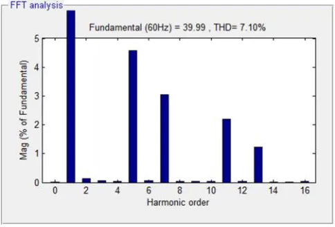
Fig 21:harmonic analysis of PCC voltage with harmonic rejection(VCM)
The PCC voltage has 9.17% THD in VCM without harmonic compensation mode. The PCC voltage distortion is reduced to 7.10 % in harmonic compensation mode. At last harmonic rejection mode introduces the polluted PCC voltage with THD of 18.77 %.
VI. CONCLUSION
This paper mainly focuses on the opportunities of distribution system power quality improvement using system DG interfacing inverters. Hear both current controlled and voltage controlled methods are implemented and their PCC voltage harmonic compensation schemes are investigated and compared. It has been shown that the proposed VCM scheme can operate at compensation, rejection and uncontrolled modes, which is more flexible than current controlled DG. Furthermore, the VCM method can be easily incorporated into the v-f droop control scheme of DG systems in microgrid. The proposed harmonic control methods have been verified by the simulation by using MATLAB/Simulink.
REFERENCES
[1] I. El-Samahy and E. El-Saadany, “The effect of DG on power quality in a deregulated environment,” in Proc. IEEE PESGM, 2005, pp. 2969–2976.
.
[2] IEEE Recommended Practices and Requirements for Harmonic Control in Electrical Power Systems, IEEE Std. 519-1992, Apr. 1993.
.
[5] C. J. Gajanayake, D. M. Vilathgamuwa, P. C. Loh, R. Teodorescu, andF. Blaabjerg, “Z-source-inverter-based flexible distributed generation system solution for grid power quality improvement,”IEEE Trans. Energy Convers., vol. 24, no. 3, pp. 695–704, Sep. 2009.
[6] Y. A.-R. I. Mohamed and E. F. El-Saadany, “A control scheme of gridconnected PWM source inverters for fast load voltage regulation and effective mitigation of unbalanced voltage disturbances,” IEEE Trans. Ind.Electron., vol. 55, no. 5, pp. 2072–2084, May 2008.
[7] S. Buso, L. Malesani, and P. Mattavelli, “Comparison of current control techniques for active filter applications,” IEEE Trans. Ind. Electron., vol. 45, no. 5, pp. 722–729, Oct. 1998.
[8] T.-L. Lee, P.-T. Cheng, H. Akagi, and H. Fujita, “A dynamic tuning method for distributed active filter systems,” IEEE Trans. Ind. Appl.,vol. 44, no. 2, pp. 612–623, Mar./Apr. 2008.
[9] T.-L. Lee, J.-C. Li, and P.-T. Cheng, “Discrete frequency tuning active filter for power system harmonics,”IEEE Trans. Power Electron., vol. 24, no. 5, pp. 1209–1217, May 2009.
[10]H. Fujita and H. Akagi, “Voltage regulation performance of a shunt active filter intended for installation on a power distribution system,”IEEE Trans. Power Electron., vol. 22, no. 3, pp. 1046–1053, May 2007.
[11] Y. W. Li, D. M. Vilathgamuwa, and P. C.Loh, “Microgrid power quality enhancement using a three-phase four-wire grid-interfacing compensator,”IEEE Trans. Ind. Appl., vol. 41, no. 6, pp. 1707–1719, Nov./Dec. 2005. [12] P. Jintakosonwit, H. Akagi, H. Fujita, and S. Ogasawara, “Implementation and performance of automatic gain adjustment in a shunt-active filter for harmonic damping throughout a power distribution system,” IEEE Trans. Power Electron., vol. 17, no. 3, pp. 438–447, May 2002.
[13] L. Asiminoaei, F. Blaabjerg, and S. Hansen, “Evaluation of harmonic detection methods for active power filter applications,” inProc. IEEE APEC, 2005, pp. 635–641.
[14] E. Jacobsen and R. Lyons, “The sliding DFT,” IEEE Signal Process. Mag., vol. 20, no. 2, pp. 74–80, Mar. 2003.
[15] D. N. Zmood, D. G. Holmes, and G. H. Bode, “Stationary frame current regulation of PWM inverters with zero steady-state error,”IEEE Trans. Power Electron., vol. 18, no. 3, pp. 814–822, Mar. 2003.
[16] P. Mattavelli, “Synchronous-frame harmonic control for high performance ac power supplies,” IEEE Trans. Ind. Appl., vol. 37,no. 3, pp. 864–872, May/Jun. 2001.
[17] J. M. Guerrero, L. Hang, and J. Uceda, “Control of distributed uninterruptible power supply systems,” IEEE Trans. Ind. Electron., vol. 55, no. 8,pp. 2845–2859, Aug. 2008.
[18] J. C. Vasquez, J. M. Guerrero, A. Luna, P. Rodriguez, and R. Teodorescu, “Adaptive droop control applied to voltage-source inverters operating in grid-connected and islanded modes,” IEEE Trans. Ind. Electron., vol. 56, no. 10, pp. 4088–4096, Oct. 2009.
[19] Y. W. Li and C. N. Kao, “An accurate power control strategy for power electronics- interfaced distributed generation units operating in a low voltage multi bus micro grid,”IEEE Trans. Power Electron., vol. 24, no. 12,pp. 2977–2988, Dec. 2009.
[20] F. Blaabjerg, R. Teodorescu, M. Liserre, and V. A. Timbus, “Overview of control and grid synchronization for distributed power generationsystems,”IEEE Trans. Ind. Electron., vol. 53, no. 5, pp. 1398–1409, Oct. 2006.
[22] H. Akagi, H. Fujita, and K. Wada, “A shunt active filter based on voltage detection for harmonic termination of a radial power distribution line,”IEEE Trans. Ind. Appl., vol. 35, no. 3, pp. 638–645, May/Jun. 1999.
AUTHORS PROFILE
M.Siva Prasada Reddywas born in Banaganapalle, india in 1991. He received B.Tech(Electrical and Electronics Engineering) degree from JNT University, Ananthpur in 2012. And pursuing M.Tech (Power Electronics) in RGMCET, Nandyal. His area of interests are Power electronics converters, power systems, and Electrical Machines.
E-mail:[email protected]
Mr.E.Narasimhulu was born in kurnool, india. He received the B.Tech (Electrical and
Electronics Engineering) degree from SV University, Thirupati in 2009. And received the M.Tech in NITK, Surthkal,manglore in 2011. His area of interesting Power electronic industrial drives