Abstract—Biomass gasification has received considerable attention as a partial substitute for fossil fuels power generation. In addition, the energy efficiency of biomass gasification can be greatly enhanced when operated with highly efficient power generation systems, such as solid oxide fuel cell (SOFC). The combined cycle is called integrated biomass gasification fuel cell (BGFC) system. In this research, rice straw is used as raw material for power generation as it is available in large amounts in Thailand. The objectives are finding the optimal operating conditions in order to make highest power efficiency and evaluating environmental impact of BGFC system. Aspen plus is used to perform a simulation in this study. In addition, Life cycle assessment (LCA) method is applied using global warming, acidification and eutrophication potentials. The results show that BGFC operated in the optimal conditions can generate 651.35 kW of net power output and 59.17% of efficiency. Moreover, the impact of global warming, acidification and eutrophication is 0.4077 kgCO2eq, 0.0026
kgSO2eq and 0.000148 kgPO4eq, respectively.
Index Terms—BGFC system, environmental assessment, power generation, process simulation.
I. INTRODUCTION
Nowadays, the energy crises as well as the global warming problem are still important problems the world is facing. These energy problems cause researchers to find a way which can resolve the problems and reduce the energy overconsumption. Therefore, priority should be given to the importance of discovering and researching for alternative energy, including using all possible processes to obtain such alternatives.
Biomass gasification is one of the processes that can generate alternative energy. It has a significant role at the present time as the process not only involves no use of fossil fuel but also helps reduce the release of CO2 into the air
compared to the combustion process. The potential environmental benefits from biomass power are numerous. Not only is there no use of fossil fuel in process but there are also some positive effects on the environment. Biomass residues from rice industry which are available in large amounts in Thailand can be reduced by using the residues to generate energy. Rice straw gives high heating value which is appropriate for power generation [1].
To increase the power efficiency generated by biomass
Manuscript received June 10, 2014; revised August 12, 2014.
W. Paengjuntuek and J. Boonmak are with the Chemical Engineering Department, Engineering Faculty, Thammasat University, Thailand (e-mail: pworanee@engr.tu.ac.th, m_boy_zaa@hotmail.com).
J. Mungkalasiri is with MTEC, National Science and Technology Development Agency (NSTDA), Thailand (e-mail: jitti.mungkalasiri@nstda.or.th).
gasification, a fuel cell system is required. A fuel cell is an energy conversion device that converts the chemical energy of a fuel gas directly to electrical energy and heat without the need for direct combustion as an intermediate step, giving higher conversion efficiencies than conventional thermo mechanical methods. In this research, solid oxide fuel cell (SOFC) technology combined with biomass gasification is studied. This combination is referred to as Integrated Biomass Gasification Fuel Cell System or BGFC [2]. Commercial program as Aspen plus is used to perform a simulation of BGFC system. Optimal operating conditions in order to produce highest power efficiency are evaluated.
An environmental assessment of combination system of biomass (rice straw) gasification and power plant process is studied in this research using life cycle assessment (LCA) methodology. LCA methodology is gaining attention for measuring an environment impact of the use of biomass as energy sources. The majority of the researchers agreed that LCA method is the best tool for estimation of greenhouse gas (GHG) emissions and is helpful for environmental improvement [3].
II. INTEGRATED GASIFICATION FUEL CELL SYSTEM
A. Biomass Gasification
Biomass gasification is the conversion of solid fuels (biomass) such as wood, wood-waste, rice straw and agricultural residues into a combustible gas. Combustible gas consists of carbon monoxide (CO), carbon dioxide (CO2),
hydrogen (H2) and traces of methane (CH4). This mixture is
called producer gas or syngas.
Gasification reactions, series reactions with oxygen and additional gas phase reaction, are [4]-[6]:
C + 0.5O2 CO Ho kJ mol rxn 111 /
C + H2O CO + H2 Hrxno 131 kJ/mol
C + CO2 2CO Ho kJ mol rxn172 /
C + 2H2 CH4 Hrxno 75 kJ/mol
CH4 + 0.5O2 CO + 2H2 Hrxno 36 kJ/mol
CO + 0.5O2 CO2 Ho kJ mol rxn 283 /
H2 + 0.5O2 H2O Hrxno 242 kJ/mol
CO + H2O CO2 + H2 Ho kJ mol rxn41 /
CH4 + H2O CO + 3H2 Ho kJ mol rxn 206 /
Environmental Assessment of Integrated Biomass
Gasification Fuel Cell for Power Generation System
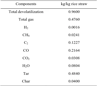
The composition of rice straw is shown in Table I.
TABLEI:COMPOSITION OF RICE STRAW AFTER PYROLYSIS
Components kg/kg rice straw Total devolatilization 0.9600
Total gas 0.4760 H2 0.0016
CH4 0.0241
C2 0.1227
CO CO2
H2O
Tar Char
0.2164 0.0308 0.0804 0.4840 0.0400
B. Fuel Cell
A fuel cell is an electrochemical energy conversion device which directly converts one part of chemical energy into electrical energy by consuming hydrogen-rich fuel and oxidant [7]. At the cathode, oxygen is reduced by the incoming electrons to produce oxygen anions that are conducted through the electrolyte to the anode where they electrochemically combine with the adsorbed hydrogen to form water and heat as a by-product and release electrons to the external circuit. The electrochemical reactions as follows [8], [9]:
At the anode: H2 + O2- H2O + 2e-
At the cathode: 1/2O2 + 2e- O2-
Overall reaction: H2 + 1/2O2 H2O +Heat + Electricity
C. BGFC System
Integrated biomass gasification fuel cell system (BGFC) is an alternative way to generate electricity from biomass with less pollution. BGFC system contains 6 main units as shown in Fig. 1. These are gasifer, cyclone, heat recovery steam generator (HRSG), gas clean up, steam turbine, and solid oxide fuel cell (SOFC).
Fig. 1. Diagram of BGFC system.
The system generates electricity from two ways, the turbine unit and SOFC unit, which has different efficiency.
D. Simulation of BGFC System
Integrated biomass gasification fuel cell (BGFC) is a significant cooperation for simultaneous heat and material integration between the gasification and the SOFC systems to generate electricity. The study is carried out by using Aspen plus version 7.2 [10]. The parameters for BGFC simulation are shown in Table II. The simulated BGFC process is composed of 6 main units illustrated in Fig. 2. Gasifier unit under consideration consists of two interconnected operation which are steam gasification and char combustion. The syngas (PRODUCT steam) rich in hydrogen from the steam gasifier passes through cyclone for Ash elimination (ASH stream) to give an excellent feedstock to the SOFC. HRSG unit is a heat exchanger. The hot nonash syngas (NONASH stream) which is at about 900°C exchanges heat with water (WATER stream).
Steam turbine unit is an isentropic expansion causing turbine work output (POWER stream) which applies this power to generate electricity. Clean up unit is for syngas cleaning. SOFC unit composed of anode and cathode. Air (HOTAIR2 stream) is fed into cathode to separate rich N2
(N2RICH stream) from O2. The left over O2 goes through the
anode to continue reaction with syngas to obtain the product gas (EXHAUST stream). SOFC unit produces more efficient power than STEAMTUR unit by calculating enthalpy and entropy of product gas (EXHAUST stream).
Predicted electrical output and power efficiency from fuel cell can be calculated by electrochemical model as follows [7]: 2 1 m RTd k m F n iA P e fc FUEL TH E o Q Q W
where
Pfc is fuel cell power
o is fuel cell efficiency
WE is Net power
= Power from fuel cell + Power from turbine ΣQTH is Net useful thermal outputs
QFUEL is Net energy input
RT E R FL in i i i i i i n i i n
d e el el
c L a L c e a
e ln1 ln1 exp
2 sinh 2 2 sinh 2 0 , , , 0 1 , 0 1 1 2 2
H H O ,
0, 0 0 exp act a a a
p p E
i
p p RT
RT E p p
i c c H act,c
4 / 1 0 , 0 exp 2 2 2 2 1/ 2 H O o o 1 H O
ln
p p
m h T s RT RTd
p
TABLEII:PARAMETERS USED IN THE SOFCMODEL
Parameters Value Ambient pressure (bar), p0
Partial pressure of H2 ; H2O, pH2 ; pH2O
Partial pressure of O2 ; N2 , pO2 ; pN2
Number of electrons participating in the reaction, ne
Pre-factor for anode exchange current densities (A/m2),
a
1 0.80 ; 0.20* 0.21 ; 0.79
2 5.5 ×10⁸
Activation energy of anode (J/mol), Eact,a
Limiting current densities of anode (A/m2), i
L,a
Pre-factor for cathode exchange current densities (A/m2),
c
1.0 ×10⁵
2.99 ×10⁴
7.0 ×10⁸
Activation energy of cathode (J/mol), Eact,c
Limiting current densities of cathode (A/m2), i
L,c
1.2 ×10⁵
2.16 ×10⁴
Thickness of electrolyte (µm), Lel
Activation energy for ion transport (J/mol), Eel
Reference ionic conductivity (S/m), 0
20 8.0 ×10⁴
3.6 ×10⁷
Ratio of the internal resistance to the leakage resistance,
k
Faraday constant (C/mol), F
Universal gas constant (J/mol K), R
1/100
96485 8.314 Standard molar enthalpy change (J/mol), ho
Standard molar entropy change (J/mol K), so
-112665* -4.09* * From Aspen simulation results at standard conditions
III. LIFE CYCLE ASSESSMENT METHODOLOGY
Life cycle assessment (LCA) is an environmental assessment tool for evaluating the impact from raw material, the manufacturing, packaging and marketing process, and use or re-use and maintenance of the product. Entire life cycle or called “cradle-to-grave” includes all the stages of a product's life [11].
Life cycle assessment is carried out in 4 distinct phases as illustrated
A. Goal and Scope
The goal and scope definition of an LCA provides a description of the product system in terms of the system boundaries and a functional unit. The functional unit is the important basis that enables alternative goods, or services, to be compared and analyzed. Further the system boundaries must be defined. This involves making choices about which processes to include or exclude in the analysis. The choice of system boundaries defines the degree of detail in the inventory analysis.
B. Life Cycle Inventory Analysis (LCI)
Life cycle inventory analysis (LCI) estimates the consumption of resources and the quantities of waste flows and emissions caused by or otherwise attributable to a product’s life cycle. It involves data collection and calculations to quantify relevant inputs and outputs of a product system.
C. Life Cycle Impact Assessment (LCIA)
It is the evaluation of potential human health and environmental impacts of the environmental resources and releases identified during the LCI. In a life cycle impact assessment, essentially two methods are followed: problem - oriented methods (mid points) and damage - oriented methods (end points).
D. Interpretation
Life cycle interpretation is a systematic technique to identify, quantify, check, and evaluate information from the results of the LCI and the LCIA, and communicate them effectively. Life cycle interpretation is the last phase of the LCA process.
In this work, an environmental assessment of combination system of biomass (rice straw) gasification and power plant or BGFC process is studied using life cycle assessment (LCA) methodology. The scope of this study is cradle to gate which is an assessment of a partial product life cycle from raw material extraction, transportation and manufacturing of the BGFC system. The functional unit is 1 kWh of electricity production. The three impact categories are evaluated as global warming, acidification and eutrophication. IPCC 2007 method is used with Thai national database for global warming impact evaluation. In addition, CML 2001 method is used for acidification and eutrophication impact evaluations.
IV. RESULTS
A. Optimal Operating Conditions
make highest power efficiency. The important operating variables that affect power performance of BGFC are temperature and pressure of gasifier and SOFC, air-to-biomass ratio and steam-to-biomass ratio. The effect of each operating variable to BGFC performance in terms of power generation from fuel cell and steam turbine, net power generation and power efficiency is shown in Fig. 3. The sensitivity results in Fig. 3 are studied at standard conditions of 3.65 air-to-biomass ratio, 1.32 steam-to-biomass ratio, 950˚C of gasifier temperature, 800˚C of fuel cell temperature, 5 bar of gasifier pressure and 1 bar of fuel cell pressure.
Fig. 3. Sensitivity study of operating variables on BGFC power generation at standard operating condition.
TABLEIII:OPTIMAL OPERATING CONDITIONS FOR BGFCSYSTEM
Optimal variables Optimum value Air-to-biomass ratio 3.4 Steam-to-biomass ratio 0.6 Temperature of gasifier (oC) 600 Temperature of fuel cell (oC) 500
Gasifier pressure (bar) 1 Fuel cell pressure (bar) 0.5
From these results, optimal operating conditions made highest power efficiency are shown in Table III. At this condition, maximum net power output and power efficiency are 651.35 kW and 59.17%, respectively.
B. Environmental Assessment
The environmental impact assessment of integrated gasification fuel cell system for power generation is analyzed with three categories as global warming, acidification and eutrophication. The functional unit of the BGFC system is 1 kWh.
The inventory (input/output) data of BGFC operation obtained from Aspen simulation as shown in Fig. 4. Using water, electricity, LPG and discharging CO2, CH4, Ash,
wastewater treatment cause global warming. Using water, electricity, LPG and discharging H2S, SO2, SO3, wastewater
treatment cause acidification. Using water, electricity, LPG and discharging NO, wastewater treatment cause eutrophication.
From the inventory data, 205 kg of rice straw can generate 651 kWh of electricity. However, it is observed that a large amount of CO2 is produced from BGFC system. The highest
contribution of CO2 production comes from biomass
gasification reaction. Syngas from gasifier unit is fed into SOFC unit. In SOFC unit, hydrogen in syngas stream reacts with oxygen ion toproduce electricity, heat and water. Thus, exhaust gas as CO2, NO, SO2 and SO3 will be released into
the atmosphere.
The environmental impact assessment in global warming, acidification, and eutrophication is shown in Table IV.
TABLEIV:ENVIRONMENTAL ASSESSMENT FOR 1 KWH OF BGFCSYSTEM
Impact category Emission Global warming kgCO2eq. 0.8640
Acidification kgSO2eq. 0.0026
Eutrophication kgPO4eq. 0.000148
However, carbon dioxide (CO2) is primarily used by the
plant as part of photosynthesis. Therefore, considering the carbon capture and storage in biomass, global warming potential will be decreased.
V. CONCLUSION
Integrated biomass gasification fuel cell or BGFC system is an alternative method of high efficient electricity generation. It not only involves an unused fossil fuel but also helps reduce the release of CO2. Many countries, including
Thailand, have many agricultural residues wastes left over from agriculture which could be reused as raw materials in form of biomass. Therefore, BGFC should be an appropriate way to generate electricity for this age of rising energy demand but declining fossil fuel. From these points, the objectives of this study are finding the optimal operating conditions in order to make highest power efficiency and evaluating environmental impact of BGFC system. Rice straw is used as raw material for BGFC power generation.
Simulation results via Aspen plus v.7.2 indicated that optimal operating conditions that produce highest power efficiency are 3.4 of air – to – biomass ratio, 0.6 of steam – to – biomass ratio, 600˚C of gasifier temperature, 500˚C of fuel cell temperature, 1 bar of gasifier pressure and 0.5 bar of fuel cell pressure. At this condition, maximum power output is 651.35 kW with highest power efficiency of 59.17%.
Considering the whole process, it was found that BGFC system releases gases and wastes out to the environment during the process. From theses points, an environmental assessment of the BGFC system is evaluated by using Life cycle assessment (LCA) methodology.
The results of environmental evaluation for 1 kWh of electricity production shown that the amounts of global warming, acidification, and eutrophication impacts are 0.8643 kgCO2eq, 0.0026 kgSO2eq, and 0.000148 kgPO4eq,
respectively. However, plant (rice) growth consumes a large amount of carbon dioxide. Thus, the global warming potential will be reduced when the carbon capture and storage in biomass are considered. Form this study, it can be concluded that BGFC rice straw power generation system has a good environmental performance with high power efficiency.
ACKNOWLEDGMENT
The authors acknowledge the support provided by Engineering Faculty, Thammasat University.
REFERENCES
[1] M. K. Delivand, M. Barz, and S. Garivait, “Overall analysis of using rice straw residues for power generation in Thailand-project feasibility and environmental GHG impact assessment,” J. of Sustainable Energy & Environment Special Issue, pp. 39-46, 2011.
[2] J. Sadhukhan, Y. Zhao, N. Shah, and N. Nigel, “Performance analysis of integrated biomass gasification fuel cell (BGFC) and biomass gasification combined cycle (BGCC) systems,” Chemical Engineering Science, vol. 65, pp. 1942-1954, 2010.
[3] S. M. Shafie, T. M. I. Mahlia, and H. H. Masjuki, “Life cycle assessment of rice straw co-firing with coal power generation in Malaysia,” J. of Energy, vol. 57, pp. 284-294, 2013.
[4] B. David, T. Braian, and F. Maohong, Coal Gasification and Its Applications, UK, Elsevier Inc., 2011.
[5] R. Anil, “Biomass Gasification,” Alternative Energy in Agriculture, pp 83-102, 1986.
[6] W. Doherty, A. Reynolds, and D. Kennedy, “Simulation of a circulating fluidised bed biomass gasifier using ASPEN Plus: A performance analysis,” in Proc. 21st International Conference on Efficiency, Cost, Optimization, Simulation and Environmental Impact of Energy Systems, Poland, 2008, pp. 1241-1248.
[7] Y. Zhao, C. Ou, and J. Chen, “A new analytical approach to model and evaluate the performance of a class of irreversible fuel cells,” Int. J. of Hydrogen Energy, vol. 33, pp. 4161-4170, 2008.
[8] R. Huberg, “Modeling of IGFC system,” The School for Renewable Energy Science in affiliation with University of Iceland & the University of Akureyri, Iceland, 2009.
[9] T. Seitarides, C. Athanasiou, and A. Zabaniotou, “Modular biomass gasification-based solid oxide fuel cells (SOFC) for sustainable development,” Renewable and Sustainable Energy Reviews, pp. 1251-1276, 2008.
[10] L. Shen, Y. Gao, and J. Xiao, “Simulation of hydrogen production from biomass gasification in interconnected fluidized beds,” Biomass and Bioenergy, vol. 32, pp. 120-127, 2008.
[11] S. Miroslava, J. Frantisek, and R. Juri, “Life cycle analysis of processes for hydrogen production,” International Journal of Hydrogen Energy, vol. 36, pp. 7844-7851, 2011.
J. Boonmak was born in Thailand. He has completed his bachelor degree of chemical engineering from Thammasat University, Thailand in 2012. He is currently enrolled in the master degree of chemical engineering from Thammasat University. His research is optimal operation analysis of integrated biomass gasification fuel cell system.