RESEARCH ARTICLE
A mechanical approach to realize
reflexive omnidirectional bending motion
for pneumatic continuum robots
Eri Takane
*, Kenjiro Tadakuma, Tomonari Yamamoto, Masashi Konyo and Satoshi Tadokoro
Abstract
A mechanism that allows a robotic arm to quickly grip various forms of objects at disaster sites will enhance the mobility of rescue robots by keeping their bodies stable and maintaining manipulability for target objects, such as debris. Such a mechanism requires the ability to quickly and omnidirectionally change arm postures toward the target and hold it in a stable manner. Continuum robots are expected to provide this functionality. Conventional continuum robots realize the function of changing arm postures and grasping objects by controlling pneumatic actuators with multiple air chambers arranged in parallel. However, conventional robots cannot be applied to potential disaster sites filled with flammable gases, gasoline, or high radiation levels because they require electronic components (e.g., solenoid valves, and sensors) to control air pressures. This study proposes a unique approach to realize reflexive omni-directional bending motion using only mechanical components without any electrical devices. The proposed system realizes a reflexive motion to bend the arm in the target’s direction by detecting a contact location using a mechani-cal reactive system. The proposed simple mechanism has the advantages of high durability and easy implementation. This paper aims to confirm the proposed concept by prototyping a drive mechanism coupled with contact detection and bending motion using mechanical port valves. We report the design concept and development of this prototype. The fundamental characteristics and feasibility of the proposed mechanism are experimentally confirmed. First, a prototype is developed using a mathematical model. Its performance in the bending and omnidirectional motions is evaluated. The results show that the model has a margin of −4.9% error in the bending angle and −7.4% error in the central curvature compared with the experimental values. We also confirm that using a higher pressure could realize a smaller radius of curvature and reduce an unnecessary twisting motion. We also tested a second prototype to confirm the grasping motion and force by changing the applied pressures. The influence of the bending direction was then evaluated. We confirm that a higher pressure generated a larger grasping force. The prototype can omnidirection-ally produce approximately the same forces although the generated forces depend on the number of air chambers excited by the contact pads. Subsequently, we experimentally confirm the influence of gravity. The test shows that the effect of own weight greatly influences the posture after the object is in contact. This effect should not be ignored. Furthermore, the curve became sufficiently large when its contact pad is pressed. This result experimentally proved that self-holding is possible. The experimental results show the potential of the proposed mechanism. Keywords: Omnidirectional bending mechanism, Continuum robots, Reflexive motion
© The Author(s) 2016. This article is distributed under the terms of the Creative Commons Attribution 4.0 International License (http://creativecommons.org/licenses/by/4.0/), which permits unrestricted use, distribution, and reproduction in any medium, provided you give appropriate credit to the original author(s) and the source, provide a link to the Creative Commons license, and indicate if changes were made.
Open Access
*Correspondence: [email protected]
Page 2 of 13 Takane et al. Robomech J (2016) 3:28
Background
Mechanisms that allow gripping of objects of various forms, sizes, fragilities, and sensitivities are highly desir-able at disaster sites. For example, a robotic arm should enhance manipulability in picking up a target object, such as a piece of debris, and should augment the mobility of rescue robots by keeping their bodies stable, such as at the end-effector of continuum robots, to perform brachi-ation inspired by animal movements. Such mechanisms require the ability to change the arm’s posture quickly and omnidirectionally toward the target to hold it stable.
Continuum robots are expected to realize the above-mentioned functionalities, and have already been intro-duced for rescue operations [1–6]. Many conventional studies report on gripper mechanisms that can accom-modate various forms of objects via deformation func-tionality using a differential coupled mechanism [7], morphing structure [8], particle jamming effects [9, 10], and flexible links [11, 12].
Most conventional continuum robots particularly real-ize the function of changing arm posture and grasping objects by controlling pneumatic actuators with multiple air chambers arranged in parallel [13–17]. The pneumatic drive, which is the beginning of it, was an explosion-proof system for coal mine machinery. It was also used as an explosion-proof measure for the gas current. There-fore, systems without electronic components (e.g., sole-noid valves, and sensors) to control air pressures can be applied in potential disaster sites filled with flammable gases, gasoline, or high radiation levels.
We propose herein a unique approach to realize reflexive omnidirectional bending motion by using only mechanical components without any electrical devices. The system proposed realizes a reflexive motion to bend the arm toward the target direction by detecting a con-tact location using a mechanical reactive system. The proposed simple mechanism has the advantages of high durability and easy implementation. This paper aims to confirm the concept and feasibility of the proposed reflexive bending mechanism coupled with contact detection using prototypes and experimentally report the fundamental characteristics. First, we discuss the possible design concepts for the omnidirectional bend-ing motion and introduce a new design to realize the reflexive motion by means of a coupled drive mecha-nism with touch detection using mechanical port valves. Second, we develop a first prototype with a mathemati-cal model and evaluate its performance in the bending and omnidirectional motions. Third, we investigate the grasping force generated and the influence of the bend-ing direction and gravity by developbend-ing a second pro-totype that can grasp a cylindrical bar by changing the applied pressures.
Methods
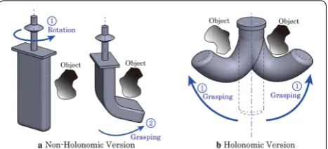
We consider herein an all-mechanical approach for a reflexive omnidirectional bending mechanism. The bending arms for the bending motion toward the direc-tion of a contacted object after detecdirec-tion of the contact with the object can be classified based on whether they are holonomic. As shown in Fig. 1a, an omnidirectional bending arm mechanism can be realized as a non-holo-nomic motion by rotating a configuration that can bend in one direction. However, the time between the contact with the object and grasping is increased because a rota-tional motion occurs after contact has been made with an object. Therefore, we employed a holonomic system that directly bends in the object direction. The bending mech-anisms for the holonomic systems have been extensively studied (e.g., Refs. [13–17]). A discussion of the designs used to realize a holonomic bending function is pre-sented on the sections that follow along with the design proposed in this paper.
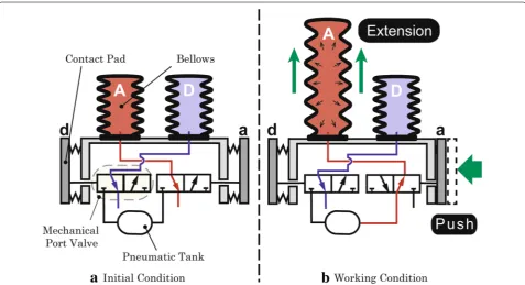
We present a concrete method to approach an all-mechanical system that reflexively bends in the direction of a contacted object. A coupled drive mechanism with touch detection using a mechanical port valve is used herein to realize the proposed mechanism. The coupled drive mechanism with this touch detection is the basic principle of a reflexive omnidirectional bending mecha-nism (Fig. 2). Air flows into the bellows on the opposite side of the device (bellows “A”) when pad “a” is pushed by an object. In this way, the configuration can bend around objects. Furthermore, the use of more than one air cham-ber allows the bending to be realized (Fig. 2). Note that the cross-sectional shape is not required to be circular.
Figure 3 presents the basic principle of mechanical touch sensing for self-bending motion using mechanical port valves. The figure illustrates a cross-sectional view of the structure shown in Fig. 2. The bellows are usually opened to the atmosphere through a mechanical port valve as shown in Fig. 3a. In addition, the contact pad
was equipped with mechanical port valves connected to the bellows on the opposite side of the device. Therefore, the bellows on the opposite side of the device connect to the pneumatic tank and extend, as shown in Fig. 3b, when an object pushes on the contact pad. This mecha-nism realizes reflexive omnidirectional bending. Figure 4 shows the design and prototype of the proposed reflex-ive omnidirectional bending mechanism with coupled drive mechanism and touch detection. Table 1 presents the prototype specifications. The prototype was designed
with six sets of valves and bellows. The use of more sets corresponds to the increased directional resolution. However, increasing the resolution is necessary to exam-ine the design stage because it leads to an increase in the part count, weight, and size. The bending motion is mod-eled in this section using this prototype. We described the model evaluation and omnidirectional motion in the next section.
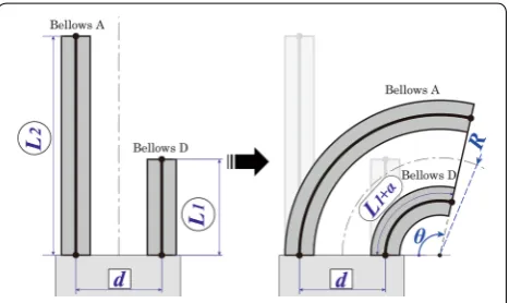
The maximum bending position after contact is mod-eled to determine the expected size of an object that the mechanism can grasp at the design stage. The maxi-mum bending position can be measured by obtaining the radius of curvature and the bending angle for each pressure if the bending motion of the one-unit system is assumed to describe an arc. We assumed that the mech-anism for this analysis exhibits zero twisting; hence, it was modeled in 2D and without gravity. Figure 5 shows the bending motion modeled on the 2D cross-section. Accordingly, d is the distance between bellows A (outside
bellows) and D (inside bellows); R is the maximum radius
of curvature of bellows D; and θ is the bending angle. In
addition, the minimum length of each bellows is labeled as L1, while L1+α corresponds to the length of bellows D during bending. Bellows D is shortened at the maxi-mum bending position, and is then extended by α. L2 is the maximum length of each bellows, while L2 at each Fig. 2 Basic design principle of the reflexive omnidirectional bending
mechanism with passive touch detection. Bellows A receives air when contact pad “a” is pushed inward through contact with an object. This configuration can then bend in the direction of the object
Page 4 of 13 Takane et al. Robomech J (2016) 3:28
Fig. 4 Photograph of the first prototype model exterior. The prototype can bend in the direction of a contacted object. A AA battery is provided to indicate scale
Fig. 5 Bending model for calculation of maximum radius of cur-vature and rotation angle. d is the distance between bellows A and the opposite, inside bellows (bellows D); R is the maximum radius of curvature of bellows D; and θ is the rotation angle. The minimum
and maximum lengths of both bellows are L1 and L2, respectively.
Bel-lows D is shortened at the maximum bending position, and is then extended by α
Table 1 First prototype model specifications
One bellows
Hardness 50
Internal/external diameter (mm) 20/35
Natural length (mm) 195
Minimum length (mm) 90
Maximum length (mm) 280
Rubber material Chloroprene rubber
Entire device
Set pressure (kPa) 20
Weight (g) 1552
External diameter (mm) 130
Minimum length (mm) 210
Maximum length (mm) 390
Radius of curvature (mm) 169 Components
Port valve MSHRP3 (MISUMI Corporation)
Regulator ITV10J1-211L (SMC Corporation)
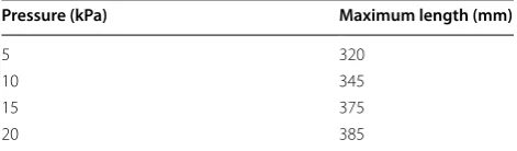
pressure is already known from the previous experiment. Table 2 shows the maximum length values of this proto-type at each pressure for bellows A. Accordingly, θ and R can be expressed as follows because of the geometric
relationship shown in Fig. 5:
The reflexive omnidirectional bending mechanism can then be extended based on this one unit. This mechanism can grasp larger objects by extending a grasping part. Furthermore, Eqs. (1) and (2) can be used in the extended versions.
The extended bellows grasping part is designed, proto-typed, and examined herein. The grasping motion for the applied pressure was particularly confirmed. The grasp-ing force was measured, and the influence of the bendgrasp-ing direction was verified.
Results and discussion
First prototype: posture measurements
We measured the bending motions using a motion cap-ture system when a contact pad was manually pushed by an experimenter’s hand to confirm the basic tempo-ral posture profiles achieved by changing the applied pressures in the chambers Fig. 6 shows the experimen-tal setup. Markers for the motion capture system were attached to the device as shown in the figure. AM02-04N (Fujiwara Sangyo Co.), which had been used in subse-quent experiments, was used as the compressor.
The initial state was defined as the attitude inclined to the left side by the prototype’s weight (Fig. 6①). The pic-tures in the series from ② to ⑥ in Fig. 6 show examples of the posture profiles when the contact pads are pushed. Figure 6⑥ shows the maximum bending posture, which depends on the applied pressure. The applied pressures in the experiments were 5, 10, 15, and 20 kPa.
Figure 7 shows the measured temporal posture profiles during the bending motion. These results confirmed that higher applied pressures produced higher speed move-ments from the initial bending state and larger curvatures.
(1) θ =
L2−(L1+α)
d ,
(2) R= (
L1+α)·d
L2−(L1+α) + d
2.
The bending movement slowed down at the final state near the maximum position. The required time to reach the maximum bending position was longer than that at 15 kPa when the pressure was 20 kPa. However, the bend-ing position reached a larger curvature. Figure 8 shows a comparison of the posture at the final state for each applied pressure. The figure clearly shows differences in the curvature depending on the applied pressure. The applied pressure also affected the twisting movement in the z-axis. The twist indicates that the track in the contact direction cannot draw a straight line on the xy plane, and the prototype cannot bend out of alignment because of individual differences of the air camber at the time of pro-duction and because a deviation occurs. Table 3 shows the RMS of the tip position errors along the z-axis for each applied pressure. The results showed that higher pressures could generate stable bending motions with smaller errors along the z-axis. These errors resulted from the unneces-sary twisting motions of the prototype, which may have been caused by the higher stiffness caused by the higher pressures in the chambers in their parallel configuration.
We then compared the theoretical posture calculated by the mathematical model described in the method sec-tion to identify the model parameters and confirm the validity of the proposed model. The model parameters include d and L1 and α, which corresponded to 90 mm and 90 mm, respectively. Accordingly, α was identified to the value closest to the experimental value from Eqs. (1) and (2). Consequently, we identified that α was 27.3 mm. Table 2 First prototype model’s maximum length of
bel-lows a for various applied pressures
Pressure (kPa) Maximum length (mm)
5 320
10 345
15 375
20 385
Page 6 of 13 Takane et al. Robomech J (2016) 3:28
Therefore, the averaged error of all the pressures was mini-mized. The maximum error of θ was −4.9% in the case of
10 kPa, and that of R was −7.4% in the case of 5 kPa. The
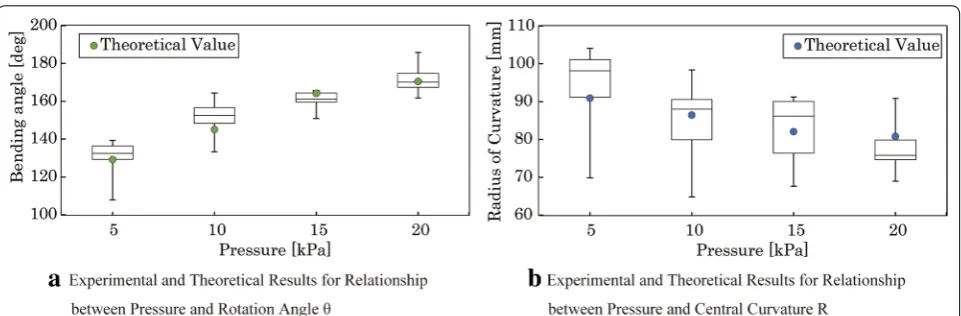
measured postures were the same as those shown in Fig. 8. Figures 9a, b show a comparison between the experimen-tal results and the theoretical values of the bending angle
θ and the radius of curvature R, respectively. The
experi-mental results showed the quantitative characteristics of the postures in the final state when the applied pressures were changed. These results agreed well with the tenden-cies, that is, higher pressures produced larger θ and smaller Fig. 7 Temporal posture profiles. a Under 5 kPa pressure, aA period of 2 s was required for maximum bending under 5 kPa pressure. b Under 10 kPa pressure, Aa period of 1.6 s was required for maximum bending under 10 kPa pressure. c Under 15 kPa pressure, Aa period of 1.4 s was required for maximum bending under 15 kPa pressure. d Under 20 kPa pressure, aA period of 1.5 s was required for maximum bending under 20 kPa pressure
R, as described earlier. We confirmed that the theoretical
values agreed well with the experimental results.
First prototype: omnidirectional reflexive motion and grasping test
The proposed mechanical configuration is expected to reflexively generate the bending motion in the direc-tion of contact. We conducted an experiment, in which the mechanism was pushed from multiple directions, to confirm the reflexive motion. All contact pads in the experiment were pressed with a wooden stick, thereby continuously changing the direction. The reflexive move-ment and bending directions were observed. Figure 10 shows an example of the reflexive bending movement when three different contact pads (i.e., #1, #2, and #3) were pressed sequentially. The series of pictures demon-strated that the proposed configuration could generate a reflexive action to directly change the bending direction from the first contact point to the next contact point. We confirmed that the prototype could bend in all other directions.
We then conducted a brief test to confirm the grip-ping capability of the first prototype. Figure 11 shows the gripping motion when the target object was a urethane sponge with a width of 60 mm. The pictures showed a Table 3 The RMS of tip position errors along the Z-axis for various applied pressures
Pressure (kPa) RMS of tip
position errors
5 9.78
10 7.88
15 6.65
20 4.30
Fig. 9 Experimental and theoretical results for the relationship between pressure and rotation angle. a Changes in θ in response to changes in the
applied pressure are shown. A roughly linear relationship is established. b Changes in R in response to changes in the applied pressure are shown. A roughly linear relationship is established
limitation of the first system in holding large objects caused by the insufficient arm length. From this obser-vation, we have confirmed that long arm length is nec-essary in grasping an object by wrapping around it. We extended the length in the following section to verify the grasping capability.
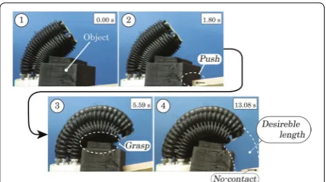
Second prototype extended grasping part: configuration We developed a longer prototype by extending the length of the bellows grasping part twice. Figure 12 shows the prototype developed when successfully grasp-ing a transparent object. Table 4 presents the prototype specifications.
The bellows parts cannot directly detect the contact events in this configuration because of the large distance between the contact pads and the grasping parts. We focused herein on the verification of our fundamental concept of the reflexive omnidirectional bending motion using an all-mechanical system. We did not discuss a sensing method for the bellows. In the future, we will consider rearranging multiple contact detection parts in a discrete manner or introducing a continuous sensing structure to combine the detection parts with the grasp-ing parts.
Second prototype extended grasping part: grasping operation
Page 8 of 13 Takane et al. Robomech J (2016) 3:28
The experimental result showed that the longer pro-totype has the potential to stably grasp and release an object.
Second prototype extended grasping part: grasping force profile measurements
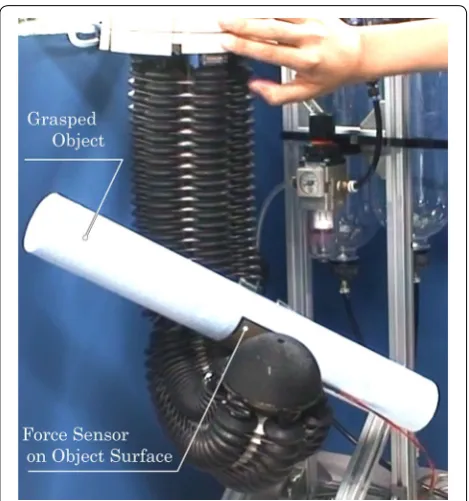
We measured the temporal force profiles during a grasp by changing the applied pressures to investigate the tran-sient response of the generated force. Figure 14 shows the experimental setup for the measurement. The tar-get object was a cylinder made of polystyrene foam with a 50 mm diameter, 400 mm length, and 20 g weight. The generated forces were measured by a force sensor
Fig. 10 Omnidirectional bending motion (top view). The photographs confirm that this configuration can bend in an omnidirectional manner rela-tive to the contact point. An additional movie file shows this in more detail (see Additional file 1)
(FSR406, Interlink Electronics, Inc.) covering the cylinder surface.
The target object was kept as level as possible by the tester and passed to the prototype under the initial con-ditions. The prototype then grasped the object for 10 s, and released it after. This process was conducted for pressures of 10, 20, and 30 kPa. Figure 15 shows the corresponding results. The grasping force for a 10 kPa pressure at the steady state was 0.50 N, while that for a 20 kPa pressure was 1.4 N. In addition, a force of more than 2.0 N was obtained when the applied pressure was 30 kPa. However, the force value did not reach a steady state within 10 s. Therefore, higher grasping force values were predicted to be obtained over a longer period of
time. Moreover, the inner pressure becomes higher, the grasping force of the second prototype becomes bigger. The realization of the desired basic grasping performance (a higher pressure corresponded to a larger grasping force) was confirmed from this experiment, in which the grasping force over a period of 10 s was measured.
Second prototype extended grasping part: influence of bending direction
The grasping force in various directions (corresponding to a given “direction angle”) was measured with the aim of ascertaining whether this configuration can provide an even grasping force in an omnidirectional manner. The direction angle was defined as shown in Fig. 16. The 30°, 90°, and 150° angles in the figure indicate that air was
Fig. 12 Photograph of the second prototype model. The second prototype is equipped to grasp an object. An additional movie file shows this in more detail (see Additional file 2)
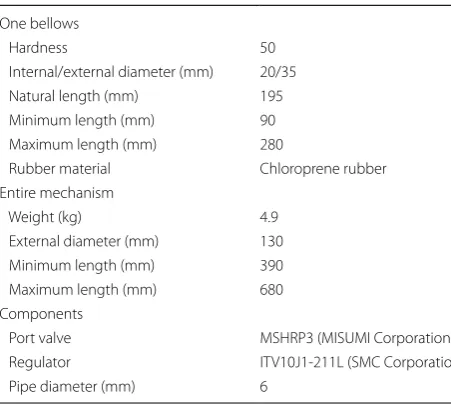
Table 4 Second prototype model specifications
One bellows
Hardness 50
Internal/external diameter (mm) 20/35
Natural length (mm) 195
Minimum length (mm) 90
Maximum length (mm) 280
Rubber material Chloroprene rubber
Entire mechanism
Weight (kg) 4.9
External diameter (mm) 130
Minimum length (mm) 390
Maximum length (mm) 680
Components
Port valve MSHRP3 (MISUMI Corporation)
Regulator ITV10J1-211L (SMC Corporation)
Pipe diameter (mm) 6
Page 10 of 13 Takane et al. Robomech J (2016) 3:28
supplied to one bellows at 30 kPa. Note that 0°, 60°, 120°, and 180° angles indicate that two bellows are supplied with air. Therefore, a higher force was predicted to be obtained for a double-bellows operation compared to the single-bellows case. Accordingly, an object made of PET with a 70 mm diameter, 200 mm length, and 145 g weight was grasped for 10 s. The average grasping force for the 9–10 s period was evaluated. The initial condition herein was fixed using a guide. Figure 17 shows the experimen-tal setup, which depicts motion at 120°.
Figure 18 presents the results. As expected, higher forces than those for the 30°, 90°, and 150° angles were
measured for the 0°, 60°, 120°, and 180° cases. The aver-age for one bellows was 2.1 N, while that for two bellows was 4.5 N. The prototype could more stably grasp the object when two bellows were used because the contact was made at two points. Overall, we have confirmed that this configuration can apply similar forces in an omnidi-rectional manner even though differences were apparent between the single- and double-bellows cases. Increasing the resolution by increasing the air camber can reduce the difference between these forces.
Second prototype extended grasping part: influence of gravity
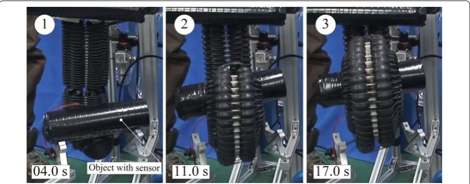
Subsequently, we experimentally observed the weight of the prototype. Observing the bending movement of the prototype with and without its own weight during 10 s with the contact pad was pushed in each situation. On the one hand, the top part of the hand is toward down in the presence of the object’s own weight. On the other hand, the hand was positioned horizontally with respect to the direction of gravity without the object’s own weight. We reduced the friction by placing the prototype on a stand equipped with a roller. The internal pressure used for the experimental conditions was 15 Pa. The tar-get object was a cylinder made of polystyrene foam with a 50 mm diameter, 400 mm length, and 145 g weight. The flow rate at the sensor (PFM550-01-1, SMC Corpo-ration) was measured in each case. Figure 19 shows the experimental results. Figure 20 presents the measured flow rate. A larger curve was observed in the case where
Fig. 14 Grasping experiment with force sensor. An object with a force sensor is grasped and the grasping force is measured for various pressures
Fig. 15 Grasping force results for various applied pressures. The changes in the grasping force over time are shown for various applied pressures
own weight was considered. As shown in ③ of Fig. 19b, the prototype pushed its own contact pad across the object after the large curve. In other words, it exhibited the object as self-holding. Furthermore, the flow meter in contact with the object for 2 s exhibited self-holding in the subsequent 3 s. The result showed that own weight greatly influenced posture after the object was in contact, and should not be ignored. The curve became sufficiently large when its contact pad was pressed. This result exper-imentally proved that self-holding was possible. Help is needed during designing to build a theoretical value in light of own weight and face the future challenges.
Conclusion
This study proposed a mechanism for achieving reflex-ive omnidirectional bending in pneumatic continuum robots. The proposed mechanism has advantages for use as an explosion- and radiation-proof system because it need not be equipped with electronic components (e.g., solenoid valves, and sensors). A mechanical system based on a coupled drive mechanism with touch detection by mechanical port valves was devised, designed, and proto-typed to realize the proposed design.
A successful realization of the proposed prototype con-figuration’s fundamental characteristics was confirmed by
Fig. 17 Photograph of device for 120° object position. An object with an attached force sensor makes contact with the prototype at an angle of 120° from the initial position. The two bellows are supplied with air in response
Page 12 of 13 Takane et al. Robomech J (2016) 3:28
modeling and conducting first prototype experiments of posture and omnidirectional motion. A second prototype was also designed to improve the grasping performance. A quantitative evaluation of the resultant grasping force and the influence of bending direction and gravity was conducted via an experiment, which demonstrated the efficacy of the proposed mechanism. We confirm that the reflexive omnidirectional bending mechanism can be extended.
The proposed design will be further refined in the future. Greater stiffness will particularly be added to the mechanism to increase its grasping force [18, 19]. Min-iaturization, smaller-force triggering, and whole-body
Fig. 19 Grasping experiment with gravity and without own weight
detection will be realized. Furthermore, a theoretical value in light of own weight must be built.
Authors’ contributions
ET and KT conceived the study, developed the device, carried out all experi-ments, analyzed data, and drafted the manuscript. TY, MK and ST partici-pated in the research design and sequence alignment. All authors read and approved the final manuscript.
Acknowledgements
This study has been done as the part of the research program ImPACT: Tough Robotics Challenge.
Competing interests
The authors declare that they have no competing interests.
Received: 24 February 2016 Accepted: 4 November 2016
References
1. Walker ID (2013) Continuous backbone “Continuum” robot manipulators. ISRN Robot, Vol. 2013, Article ID 726506. http://www.hindawi.com/jour-nals/isrn/2013/726506/. Accessed 30 Nov 2015
2. Hirose S (1987) Biologically inspired robots. Ind Comm, Japan
3. Mori M, Hirose S (2001) Development of active cord mechanism ACM-R3 with agile 3D mobility. In: Proceedings of the IEE/RSJ international confer-ence on intelligent robots and systems, p 1552–1557
4. Erkmen I, Erkmen AM, Matsuno F, Chatterjee R, Kamegawa T (2002) Ser-pentine search robots in rescue operation. IEEE Robot Autom Mag 9(2):17 5. Ayers J, Wilbur C, Olcott C (2000) Lamprey Robot. In: Proceedings of the
1st international symposium on aqua bio-mechanisms, p 327–332 6. Nabil S, Kai X (2013) US Patent US20130090763A1
Additional files
Additional file 1. The movie confirm that this configuration can bend in an omnidirectional manner relative to the contact point.
Additional file 2. The second prototype is equipped to grasp an object.
7. Hirose S (1986) Differential coupled mechanism and its application. Draft Design 21(10):362–366
8. Tadakuma K, Tadakuma R, Teshigawara S, Mizoguchi Y, Hasegawa H, Terada K, Takayama T, Omata T, Ming A, Shimojo M (2008) The morphing omnidirectional gripper “Morphing Omni-Gripper” with low melting point alloy. The 26th Annual Conference of The Robotics Society of Japan, 1E1-01
9. Bancon G, Huber B (1982) Depression and grippers with their possible applications. 12th ISIR, Paris, p 321–329
10. Brown E, Rodenberg N, Amend J, Mozeika A, Steltz E, Zakin MR, Lipson H, Jaeger HM (2010) Universal robotic gripper based on the jamming of granular material. Proc Natl Acad Sci 107:18809–18814
11. Clement MG, Thierry L (1998) US Patent 5,762,390
12. Dollar AM, Howe RD (2010) The highly adaptive SDM hand: design and performance evaluation. Int J Robot Res 29(5):585–597
13. Rolf M, Steil JJ (2014) Efficient exploratory learning of inverse kinemat-ics on a bionic elephant trunk. IEEE Trans Neural Netw Learn Syst 25:1147–1160
14. Suzumori K (1989) Flexible Microactuator (1st Report, Static Characteris-tics of 3 DOF Actuator). Trans Jpn Soc Mech Eng Ser C 55(518):2547–2552 15. Otherlab. https://otherlab.com/. Accessed 26 Jun 2015
16. McMahan W, Jones B A, Walker I D. (2005) Design and Implementation of a multi-section continuum robot: air-octor. In: Proceedings of the IEEE/RSJ international conference on intelligent robots and systems, p 3345–3352
17. Tsukagoshi H, Kitagawa A, Segawa M (2001) Active hose: an artificial elephant’s nose with maneuverability for rescue operation. In: Proceed-ings of the 2001 IEEE international conference on robotics & automation, p 2454–2459
18. Kim YJ, Cheng S, Kim S, Iagnemma K (2013) A novel layer jamming mech-anism with tunable stiffness capability for minimally invasive surgery. IEEE Trans Rob 29:1031–1042