ORIGINAL ARTICLE
Ali Awaludin · Takuro Hirai · Toshiro Hayashikawa Yoshihisa Sasaki · Akio Oikawa
Effects of pretension in bolts on hysteretic responses of moment-carrying
timber joints
Abstract The adoption of a concept similar to the prestress-ing technique used in laminated wood decks of bridge struc-tures might increase the initial stiffness or ultimate resistance of dowel-type timber joints by applying pretension to their bolts. This study investigated the effect of pretension in bolts on hysteretic responses and ultimate properties of moment-carrying timber joints with steel side plates. A pretension of 20 kN that yielded a prestress level of 1600 kPa or about 90% of the allowable long-term end-bearing strength of spruce species was applied to the bolts of prestressed joints. The superiority of the prestressed joint over the non-pre-stressed joint was proved by very high hysteretic damping, equivalent viscous damping ratio, and cyclic stiffness. At any given rota-tion level, hysteretic damping reducrota-tion and moment resis-tance decrement due to continuously reversed loads were found to be small because bolt pretensioning minimized the pinching effect. This study showed that the hysteresis loop of the prestressed joint can be obtained by adding the frictional hysteresis loop due to pretension force into the hysteresis loop of the non-pre-stressed joint. Despite a great increase of initial stiffness, only slight increments in ductility coeffi -cient and ultimate moment resistance were found in the prestressed joint.
Key words Pretension · Hysteretic response · Bolted joint · Pinching effect
A. Awaludin (*)
Laboratory of Bridge and Structural Design Engineering, Graduate School of Engineering, Hokkaido University, Kita 13 Nishi 8, Kita-ku, Sapporo 060-8628, Japan
Tel. +81-11-706-6170; Fax +81-11-757-8159 e-mail: awaludin@eng.hokudai.ac.jp
T. Hirai · Y. Sasaki
Graduate School of Agriculture, Hokkaido University, Sapporo 060-8589, Japan
T. Hayashikawa · A. Oikawa
Graduate School of Engineering, Hokkaido University, Sapporo 060-8628, Japan
Introduction
It has been reported that prestressing develops frictional resistance between laminas and by this an improvement of the structural performances of laminated wood decks can be obtained.1,2
In the fi eld of timber connections, especially with dowel-type fasteners, a similar improvement could also be achieved by introducing pretension to their fasteners. Through a monotonic test, Quenneville and Dalen3
demon-strated that pretension in bolts enlarged the initial stiffness of split-ring timber joints besides increasing their lateral load-carrying capacities. Because loss of prestress (stress on wood member due to fastener pretensioning) may occur due to various factors,4,5
a minimum prestress level of 690 kPa at the time of construction has been recommended.6 Higher prestress levels (1500 kPa and 3000 kPa) were also applied to the bolts of split-ring joints to improve their structural performances.3
In spite of its general application, the dowel-type timber joint is characterized by a very low stiffness at initial loading due to the existence of lead-hole clearance.7,8
Increasing the initial stiffness or load-carrying capacity of timber joints with dowel-type fasteners therefore could be done by apply-ing pretension to the bolts. However, those improved per-formances were required to be further investigated under cyclic or dynamic loadings before being widely imple-mented. The objective of this study was to examine the effects of pretension in bolts on cyclic properties and ulti-mate strength of moment-carrying timber joints with steel side plates.
Materials and methods
Spruce–pine–fi r glued laminate of 2.44 m in length was fabricated by using three laminas bonded with resorcinol-formaldehyde resin adhesive. Cold pressing was performed at room temperature for 24 h at 0.7 MPa. A joint specimen shown in Fig. 1 is composed of two glued laminated lumbers Received: January 17, 2007 / Accepted: August 13, 2007 / Published online: November 7, 2007
that were connected to each other by two steel gusset plates of 4 mm thickness and 12-mm bolts. The grade of steel used for the bolts and gusset plates was SS400 according to JIS G 3101.9
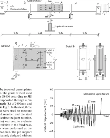
This joint specimen was supported through a pin system at both ends with a span length (L) of 3800 mm and was loaded at two points as shown in Fig. 1. In this test, three displacement transducers (LVDTs) were used to measure the relative slip between the wood member and the steel plate, which was further used to calculate the joint rotation. In addition, one potentiometer (Pm) was used to evaluate the midspan vertical displacement relative to the fi xed base. These displacement measurements were performed at the front and back sides of the joint specimen. The pin support system as shown in Fig. 1 was particularly designed without drilling holes in the wood member and it allowed the joint specimen to rotate and slide horizontally at both ends. The applied load was controlled using a displacement-controlled rate of 3.75 mm/min for the midspan vertical displacement.
The cyclic test protocol shown in Fig. 2 consisted of six midspan vertical displacement levels: 4.5, 9, 13.5, 18, 22.5, and 27 mm. At any displacement level, the cyclic load was repeated fi ve times before going to the next level. Free vibration test that was carried out by giving an impact load using wooden hammer at the midspan of the joint speci-mens was conducted before and after the cyclic test to examine the effect of cyclic load application on vibration characteristics. In-plane vertical acceleration during the free vibration test was recorded with some accelerometers (see Fig. 1) and was used to evaluate the natural frequency of the joint specimens by using LabVIEW.10 In a quasistatic monotonic test, the specimens were loaded in the down-ward direction until failure or to 200 mm of midspan vertical displacement.
Six non-pre-stressed joints, six prestressed joints, and three standard joints were prepared and directly tested. All these joint specimens had the same joint geometry. An axial bolt pretension of 20 kN was applied to each fastener of the prestressed joints by using a calibrated torque wrench device. Based on the contact area between the wood member and the steel gusset plate, the prestress level on the wood member due to the bolt pretension of 20 kN was approxi-mately equal to 1600 kPa, which is about 90% of the allow-able long-term end-bearing stress of spruce species (1760 kPa).11
The non-pre-stressed and prestressed joints were subjected to both free vibration and cyclic tests before fi nally loaded monotonically up to failure. The standard joints were loaded only monotonically up to failure and no axial pretension was applied to their bolts.
0.2L 0.2L 0.3L
0.3L
Accelerometer
B A
Grain orientation
Detail B
t
Pm
Detail A CL a
b c
c d
d e
f
LVDT 3
LVDT 1
LVDT 2
Pm
Bolt
Hydraulic actuator
Fig. 1. Test setup of moment-resisting joint. a = 7D (84 mm);
b = 10D (120 mm); c = 7.5D (90 mm); d = 4D (48 mm);
e = 100 mm; f = 65 mm; h = 280 mm; t = 100 mm; D is bolt diameter = 12 mm; lead-hole clearance = 1 mm; L, span length
= 3800 mm; LVDT, displacement transducer; Pm, potentiometer
-60 -40 -20 0 20 40 60
Vertical displacement (mm)
Cyclic test
Monotonic up to failure
9 mm
18 mm
27 mm
Time
After the tests, small wood specimens were cut from the vicinity of the connection to evaluate the moisture content, specifi c gravity, and dowel-bearing strength. The average moisture content and specifi c gravity were found to be 13.11%, and 0.38, respectively. The bearing strength test yielded 5% offset dowel-bearing strength parallel to the grain of 26.62 MPa with a coeffi cient of variation of 8.1%. Monotonic tension tests on three replicates of 12-mm bolts showed an average ultimate tension–stress of 440 MPa, and proportional tension–stress of 273 MPa. As a result, the tension–stress in the bolt due to pretension of 20 kN was about 177 MPa and it was still in the elastic range.
Results and discussion
The standard joint specimens reached an average ultimate moment resistance of 13.99 kNm and failed due to wood member splitting after having some bending deformation on their fasteners. In this study, the center of joint rotation was assumed to be fi xed during loading so that the joint rotation could satisfactorily be evaluated only based on measurements of two LVDTs (LVDTs 1 and 2, see Fig. 1). Ultimate joint rotation of the standard specimens ranged from 0.089 to 0.135 radians with an average value of 0.111 radians, while the joint rotation corresponded to 27 mm of midspan vertical displacement as the cyclic test varied from 0.0135 to 0.0161 radians. The maximum rotation of the cyclic test therefore was about 10% of the ultimate rotation of the standard specimens or was in the serviceability range.12 However, the corresponding dowel embedment had reached the inelastic portion of the bearing stress–embedment curve shown in Fig. 3. For instance, the joint rotation of 0.0135 radians embedded the outermost bolts into the wood member by 0.96 mm; assuming 0.5 mm of lead-hole clearance.
Typical hysteresis curves of both non-pre-stressed and prestressed joints obtained from the cyclic test are shown in Fig. 4, where a pinching mechanism or less resistance at rotation close to zero points was observed in both hysteresis loops, especially in the non-pre-stressed joint. The magni-tudes of moment resistance in the positive and negative directions of most hysteresis loops were found to be unequal because of natural randomness of lead-hole clearance among the fasteners. In fact, this eccentricity was also found even for single-nailed or single-bolted timber joints and it was strongly dependant on the selected cyclic test proto-col.7,13
Less moment resistance was found in the non-pre-stressed joint compared with the prestressed joint for the same rotation level.
When the hysteresis loop of the prestressed joint is sub-tracted by the same amount of the hysteresis loop of the non-pre-stressed joint, a square hysteresis curve is obtained as an indication of frictional damping due to prestressing application. In other words, the hysteresis loop of pre-stressed joints can be obtained by simply adding the frictional hysteresis loop due to prestress force into the hysteresis loop of non-pre-stressed joints. Besides frictional force due to initial prestressing, frictional force in bolted timber joints may also be introduced by secondary axial force due to bending deformation of laterally loaded bolts.14 The hysteresis loop caused by this secondary axial force could be constructed in a similar way as the loop due to initial prestressing force and the magnitude of this loop depends essentially on the static coeffi cient of friction, which is affected by many parameters.15
Three properties were used to defi ne the cyclic perfor-mance of the joint: (1) hysteretic damping, ED; (2) equiva-lent viscous damping ratio, zeq; and (3) cyclic stiffness, krc. Figure 5 shows a typical hysteresis loop of a non-pre-stressed joint along with information required to calculate the three properties. The equivalent viscous damping ratio evaluated according to Fig. 5 was only an approximation because a
0 10 20 30 40
0 1 2 3 4 5
Embedment (mm)
Bearing stress (MPa)
Fig. 3. Result of dowel-bearing test for loading parallel to the grain
-12 -10 -8 -6 -4 -2 0 2 4 6 8 10 12
-0.02 -0.015 -0.01 -0.005 0 0.005 0.01 0.015 0.02
Joint rotation (rad)
Moment resistance (kNm)
Non-prestressed joint
Prestressed joint
complex damping mechanism is naturally found in dowel-type timber joints.16,17
The hysteretic damping is the area enclosed by the moment rotation curve, while the potential energy is the area of the triangle shown in Fig. 5. Because most of hysteresis loops were not symmetrical, the area of the triangle in both directions was averaged to accurately evaluate the potential energy. Finally, the cyclic stiffness as defi ned in Fig. 5 indicates how connection “softens” or degrades during the loading. The values of the cyclic proper-ties for three different cyclic rotation levels are summarized in Table 1 where the hysteretic damping was evaluated by using SPSS SigmaScan.18
Cyclic rotations of 0.0047, 0.0093, and 0.0148 radians corresponded to 9, 18, and 27 mm of midspan vertical displacement, respectively.
Table 1 shows that the hysteretic damping of the pre-stressed joint is several times greater than that of the non-pre-stressed joint. Hysteretic damping of the non-non-pre-stressed joints decreased as the number of cycles increased and its reduction occurred with a greater rate when the joints were cycled at higher rotation levels. The average hysteretic damping reductions of the non-pre-stressed joint at cyclic
rotations of 0.0047, 0.0093, and 0.0148 radians were about 5.17%, 9.66%, and 17.27%, respectively. On the other hand, the hysteretic damping of the prestressed joints during initial and last cycles was not much different because the frictional resistance minimized the inelastic slip component of viscoelastic damage to the wood fi bers. Although the amount of damping reduction increased as the cyclic rota-tion level increased, the maximum reducrota-tion of hysteretic damping of the prestressed joint was found to be less than 5%.
The equivalent viscous damping ratio shown in Table 1 was evaluated using the hysteresis loop of the last cycle. The equivalent viscous damping ratio of non-pre-stressed joints decreased sharply as the cyclic rotation level increased and it was essentially caused by narrowing of the hysteresis loop at rotations close to the zero point. The equivalent viscous damping ratio of prestressed joints remained fairly constant for all cyclic rotation levels tested in this study. Frictional damping due to friction between joint members greatly increases the equivalent viscous damping given in Table 1, especially in the case of prestressed joints. For an earth-quake-resistance design, therefore, the magnitude of equivalent viscous damping ratio summarized in Table 1 is required to be further examined at some higher rotation levels and also by considering loss of prestress force (stress relaxation).
Within a given rotation level, the continuously reversed cycles caused stiffness to decrease from the initial cycle to the fi nal cycle. Decrease in cyclic stiffness from the initial to the fi nal cycle ranged from 6% to 10% at non-pre-stressed joints, and from 2% to 6% at prestressed joints. The remain-ing inelastic slip component of viscoelastic damage of wood fi bers during previous cycles potentially caused this cyclic stiffness degradation, which was also manifested through the decrease of moment resistance as shown in Fig. 6. In Figure 6, the moment resistance data at all cycles was con-verted to moment retention (Mn/M1), that is, the ratio of moment resistance at nth cycle to the moment resistance at the fi rst cycle. By increasing the number of cycles, moment resistance of the non-pre-stressed joint decreased exponen-tially and it can be assumed to fi nally stabilize after four or fi ve cycles. Moment resistance degradation of the pre-stressed joint, however, occurred almost linearly up to the
Table 1. Cyclic properties of non-pre-stressed and prestressed joints at some rotation levels
Joint ED (kNm-rad) zeq krc (kNm/rad)
Initial Final Final Initial Final
Non-pre-stressed
0.0047 rads 0.0108 (0.0057–0.0136)a 0.0100 (0.0054–0.0129) 0.24 (0.17–0.34) 334 (196–503) 313 (175–496) 0.0093 rads 0.0208 (0.0133–0.0264) 0.0174 (0.0106–0.0239) 0.16 (0.14–0.19) 266 (166–361) 239 (165–316) 0.0148 rads 0.0322 (0.0217–0.0390) 0.0264 (0.0165–0.0323) 0.10 (0.09–0.10) 257 (127–358) 236 (124–326) Prestressed
0.0047 rads 0.0517 (0.0466–0.0586) 0.0514 (0.0466–0.0580) 0.33 (0.30–0.37) 1558 (1235–1780) 1471 (1216–1760) 0.0093 rads 0.1692 (0.1641–0.1752) 0.1654 (0.1581–0.1744) 0.34 (0.32–0.36) 732 (633–785) 713 (621–771) 0.0148 rads 0.2689 (0.2545–0.2816) 0.2603 (0.2503–0.2708) 0.32 (0.31–0.33) 516 (421–617) 489 (416–575)
ED, Hysteretic damping; zeq, equivalent viscous damping; krc, cyclic rotational stiffness a Values in parentheses are minimum and maximum values
Hysteretic damping
Cyclic stiffness Potential energy
Hysteretic damping Potential energy =
ζeq 41π
last cycle with a lower degradation rate than that of the non-pre-stressed one. When cyclically loaded up to joint rotation set at 0.0148 radians, the average moment reduc-tion of the non-pre-stressed and prestressed joints was about 17.5% and 5.25%, respectively.
Even though the prestressed joint had greater hysteretic damping and cyclic stiffness than the non-pre-stressed one, only slight difference of fundamental natural frequency was found between the joints (see Table 2). The free vibration test results shown in Fig. 7 indicated that that the in-plane vertical acceleration of the non-pre-stressed joint was found to decrease more rapidly than that of the prestressed joint. Assuming that the free vibration test was carried out at a very small rotation level, the signifi cant pinching mecha-nism observed in the non-pre-stressed joint seemed to have a positive effect in maintaining the overall dynamic response of joint specimens. Average reduction of fundamental natural frequency as an indicator of stiffness decrement was found to be about 9.13% and 4.05% for the non-pre-stressed and prestressed joints, respectively. Higher reduction of the natural frequency found in the non-pre-stressed joint was essentially affected by the joint deformation at zero resis-tance as observed during initial loading of the quasistatic monotonic test.
The relationship between moment resistance and joint rotation up to failure shown in Fig. 8 clearly shows that the pretension in bolts largely increases the initial rotational stiffness, given by the slope of the linear part at initial moment rotation curve, but slightly enhances the maximum
70 80 90 100
110
1 2 3 4 5 6
Number of cyclic loadings (n)
M
n
/M
1
(%)
Prestressed joint Non-prestressed joint
0.0093 rads 0.0047 rads
0.0148 rads
17.5% 5.25%
Fig. 6. Moment retention of non-pre-stressed and prestressed joints.
Mn/M1, Moment retention (ratio of moment resistance at the nth cycle to the moment resistance at the fi rst cycle)
Non-prestressed joint
Prestressed joint
T = 0.039 s
T = 0.039 s
f = 1/T = 25.64 Hz
Vertical acceleration (gal)
Vertical acceleration (gal)
Fig. 7. In-plane vertical acceleration during free-vibration test. f, Natural frequency; T, period
0 4 8 12 16 20
0.00 0.04 0.08 0.12 0.16 0.20
Joint rotation (rad)
Moment resistance (kNm)
Non-prestressed joints (N-Pj) Prestressed joints (Pj)
Pj N-Pj
kri (kNm/rad)
Mmax (kNm)
θMmax (rad) θmax (rad)
663 2,467
13.42 14.87
0.073 0.054
0.090 0.083
Fig. 8. Moment rotation curve obtained from quasistatic monotonic test. kri, Initial rotational stiffness; Mmax, maximum moment resistance;
qMmax, joint rotation at moment resistance Mmax; qmax, ultimate joint rotation
Table 2. Fundamental natural frequency of non-stressed and pre-stressed joints
Joint type f (Hz)
Non-pre-stressed joint
Before cyclic load 31.35 (29.49–34.38)a
After cyclic load 28.55 (21.73–31.84)
Reduction 9.13% (2.51–10.69)
Prestressed joint
Before cyclic load 34.28 (32.81–36.13)
After cyclic load 32.88 (31.84–33.61)
Reduction 4.05% (2.24–7.03)
moment resistance. The fastener of the prestressed joint was bent with a smaller fi nal bending angle than that of the fastener of the non-pre-stressed joint. Thus, additional resistance due to steel plate embedment into the wood member or so-called secondary friction of the fastener bending deformation was higher in the case of the non-pre-stressed joint than that of the prestressed one. The ulti-mate joint rotation defi ned as the rotation that corresponded to failure rotation or at 80% of maximum resistance, which-ever occurred fi rst in the test, was almost the same for both non-stressed and prestressed joints. However, the pre-stressed joint reached the maximum moment resistance at a smaller joint rotation than did the non-pre-stressed joint. As a result, the ductility coeffi cient (the ratio of ultimate rotation to joint rotation at maximum moment resistance) of the prestressed joint was higher than that of the non-pre-stressed joint. The ductility coeffi cients were 1.23 and 1.54, respectively, for non-pre-stressed and prestressed joints. The quasistatic monotonic test of the non-pre-stressed joint yielded an average maximum moment resistance of 13.42 kNm, which is roughly the same as the maximum moment resistance of the standard joints. The introduction of cyclic loads up to joint rotation of 10% of the ultimate rotation did not have adverse effects on the maximum moment resistance.
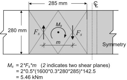
Figure 8 shows a sudden decrease of rotational stiffness of the prestressed joints as an indication of slip between steel and wood members. The same slip occurrence is also observed in the hysteresis loop shown in Fig. 4 and occurred as the applied moment exceeded the frictional/sliding moment resistance. From six specimens, the average moment resistance at this slip occurrence was found to be about 4.78 kNm. Sliding moment resistance (Ms) of the joint due to frictional resistance between the wood member and the steel plate could be evaluated based on two frictional forces shown in Fig. 9. If a static friction coeffi cient of 0.3 is assumed,19
this moment resistance will be 5.46 kNm and is about 14% higher than the experimental result. This deviation might be caused by instant stress relaxation experienced by the fasteners because there was an interval between prestressing and the cyclic test.
Conclusions
Quasistatic cyclic tests performed in this study showed that the introduction of pretension force to fasteners improves the structural performances of moment-carrying timber joints. The area enclosed by hysteresis loop, the so-called hysteretic damping, of the prestressed joint was several times greater than that of the non-pre-stressed joint. Pinch-ing or narrowPinch-ing of the hysteresis loop around zero rotation points as generally found in the non-pre-stressed joint was largely minimized. The positive effects of bolt pretensioning were further proved by a lower rate of reduction of moment resistance when cyclically loaded multiple times at same rotation level. Continuously reversed loads at any desig-nated rotation level caused the moment resistance of the prestressed joint to decrease linearly with a lower degrada-tion rate than that of the non-pre-stressed joint. The appli-cation of cyclic loads up to a rotation level of 0.0148 radians reduced the moment resistance by 17.25% and 5.25%, respectively, for the non-pre-stressed and prestressed joints. However, it did not have adverse effects on the maximum moment resistance. A large increase of initial stiffness due to bolt pretensioning was followed by slight increases in ultimate resistance, ductility coeffi cient, and natural frequency.
Acknowledgments A.A. expresses sincere gratitude to the Japan International Cooperation Agency (JICA) through the AUN/SEED-Net Program for the educational scholarship. The authors thank Ms. Honma Chiemi and Mr. Takahashi Yusuke, for helping A.A. with the laborious task of specimen testing.
References
1. Ritter MA, Wacker JP (1995) Field performance of stress-laminated timber bridge on low-volume roads. In: Proceedings of the 6th International Conference on Low-Volume Roads, Minne apolis, pp 347–356
2. Wipf TJ, Ritter MA, Wood DL (1999) Dynamic evaluation and testing of timber highway bridges. In: Proceedings of Pacifi c Timber Engineering Conference, Rotorua, pp 333–340
3. Quenneville JHP, Dalen KV (1991) The enhanced performance of split-ring connections through prestressing. Can J Civil Eng 18:830–838
4. Kainz JA, Ritter MA (1998) Effect of cold temperature on stress-laminated timber bridge-decks. In: Proceedings of the 5th WCTE, Montreaux, pp 42–49
5. Sarisley EF, Accorsi ML (1990) Prestress level in stress-laminated timber bridge. J Struct Eng 116:3003–3019
6. American Association of State Highway and Transportation Offi cials (1991) Guide specifi cations for the design of stress-laminated wood decks. American Association of State Highway and Transportation Offi cials, Washington DC
7. Prion H, Foschi R (1994) Cyclic behaviour of dowel type connec-tion. In: Proceedings of the Pacifi c Timber Engineering Confer-ence, Gold Coast, pp 21–27
8. Mesic E (2003) Analysis of timber frames with localized nonlin-earities. Facta Univ Architect Civil Eng 2:307–320
9. Japanese Industrial Standards Association (1987) Japanese Industrial Standard JIS G 3101. Rolled steel for general struc-ture (in Japanese). Japanese Industrial Standards Association, Tokyo
10. National Instruments (1996) LabVIEW 4. National Instruments, Austin, TX, USA
280 mm
285 mm CL
F
sMs=2*Fs*m (2 indicates two shear planes) = 2*0.5*(1600*0.3*280*285)*142.5
= 5.46 kNm
F
sMs
m Symmetry
Fig. 9. Evaluation of sliding moment resistance (Ms). Fs, frictional force
=m× p × A; m, coeffi cient of static friction; p, prestress on wood member;
11. Architecture Institute of Japan (2006) Standard for structural design of timber structures. Architecture Institute of Japan, Tokyo, pp 13–14, 400
12. Karacabeyli E, Yasumura M, Foliente GC, Ceccotti A (2005) Back-ground information on ISO standard 16670 for cyclic testing of connections. In: Proceedings of the 38th CIB-W18, Karlshure, paper no. 38-15-1
13. Wakashima Y, Hirai T (1993) Hysteretic properties of nailed timber-plywood joints under cyclic loading I: static cyclic loading test (in Japanese). Mokuzai Gakkaishi 39:1259–1266
14. Hirai T (1991) Analysis of the lateral resistance of bolt joints and drift-pin joints in timber II: numerical analysis applying the theory of a beam on an elastic foundation (in Japanese). Mokuzai Gak-kaishi 37:1017–1025
15. Chang WS, Komatsu K, Hsu MF, Chen WJ (2007) On mechanical behavior of timber shear wall in Taiwan. J Wood Sci 53:17–23 16. Dolan JD, Toothman A (2002) Monotonic and cyclic tests of shear
wall with gypsum wallboard, fi berboard, and hardboard sheathing. Report No. WMEL-2002-03. Wood Materials and Engineering Laboratory, Washington State University, Pullman
17. Chopra AK (2001) Dynamics of structures: theory and applications to earthquake engineering. Prentice Hall, Upper Saddle River, pp 99–104
18. SPSS (1999) SigmaScan Pro 5.0.0: Image Analysis. SPSS, Chicago, IL, USA