http://www.sciencepublishinggroup.com/j/ajcbm doi: 10.11648/j.ajcbm.20180201.13
Wooden I-Beams Made of Round Timber with a Core Rot
Viktor Yevgenyevitch Byzov
Department of Metal and Wooden Designs, St. Petersburg State University of Architecture and Civil Engineering, St. Petersburg, Russia
Email address:
To cite this article:
Viktor Yevgenyevitch Byzov. Wooden I-Beams Made of Round Timber with a Core Rot. American Journal of Construction and Building Materials. Vol. 2, No. 1, 2018, pp. 16-21. doi: 10.11648/j.ajcbm.20180201.13
Received: July 31, 2018; Accepted: August 22, 2018; Published: October 6, 2018
Abstract:
Round timber with core rot was not used in the production of sawn timber for load-bearing building structures. The purpose of this work is the researches of a possibility of receiving wooden beams from round timber with a core rot. The wooden I-beam made of angular elements of the received their round forest products with decay was chosen as the object being studied. The design scheme for determining strength and deflections of the beam is a statically determinate hinged beam, loaded with a uniformly distributed load. The design spacing of the structure is assumed to be 6 meters. Under the action of a load equal to 1.5 kN/m, the beam is exposed to stress-strain state of transverse bending. A method for manufacturing I-beams from corner elements obtained as a result of cutting round logs with core rot is proposed. It has established that the calculated strength characteristics of I-beams produced according to the proposed technology may resist operational loads. Rated and tangential stresses arising from application of loads do not exceed the permissible values. Deflection of a beam does not exceed allowable deflection values. The use of round timber with core rot increases resources of wood for construction.Keywords:
I-Beam, Low-Grade Forest Products, Angle Bar Elements, Strength Characteristics of Wood1. Introduction
I-beams from wood are now widely used in the construction of buildings and structures. They are used for installation of ceilings, rafters, installation of floors and strapping on the foundation. The cross-sectional shape of the beam ensures a good performance of the structure in terms of bending under operating conditions. In terms of their performance, they are not inferior to metal and reinforced concrete structures, and they have less weight. Beams withstand design loads, both at small and large spans (up to 12 m). However, modern construction experience shows the expediency of using I-beams for spans from 2 to 6 m [1].
The advantages of I-beams refer to light weight, high safety margin, ease of transportation and installation and cost-effectiveness. Light weight, about 50 kN/running meter, allows you working without heavy equipment. The high speed of installation and ease of assembly increase adaptability of erection of buildings and structures. After treatment with special compounds, the wood of the beams has the required fire resistance, resistance to decay and insect damage. There is a great demand for such beams in seismically dangerous areas of construction. The ecological properties of wood beams are not questioned. The retail price
of I-beams is not high. For example, cost of a beam with a height of 200 mm and dimensions of the cross section of the belts of 42 x 85, is about 300 rubles per running meter.
Calibrated block of glued timber is used for production of shelves in the beams manufactured using the technology proposed in Canada, and the walls are made of oriented structural boards OSB-3 and OSB-4. In Russian conditions, most walls are made from plywood and rarely from LVL.
A large number of works have been devoted to the study of the features of I-beams. In particular, the publication of [2] presents the results of tests of an I-beam with a wall from OSB. In the paper [3], strength and wood elasticity of composite beams with a wall from an oriented structural board are considered. In the studies performed [4-17], the issues of influence of anisotropy of the wood properties and various methods of fastening and strengthening on the stress-strain state of the structure have been considered.
chemical-mechanical processing of wood raw materials or wood. Only additional treatment and processing of low-grade wood allow using it for production of short-length sawn timber and rough furniture blanks.
Studies have established that the change in diameter of the stump rot along the length of the tree trunk occurs in accordance with law of constancy of relative growth [18]. In accordance with this law, the diameter of the stump rot in an arbitrary section of the tree trunk is determined by the formula:
b r= r0 r,
d d -al
(1)where
d
r - diameter of stump rot in an arbitrary cross-section, m;d
r0- diameter of rot at the butt-end of round product range, m;l
r- length affected with stump rot, m;a,b
- constants of initial condition and balance, respectively.The main task of sawing low-quality round timber is to obtain the maximum quantity of sawn timber with the required quality and free from any rot. The studies [19] have suggested a log cutting plan on the generator line, taking into account the structure of wood and its physical and mechanical properties.
Recently, methods for cutting low-quality round timber with core rot in order to produce sawn timber of a large cross-section have been proposed. For example, it has been proposed to fix the timber with regard to healthy peripheral region and divide the timber into sectors in the longitudinal direction. For the maximum quantity of useful wood round forest products and a bar sawed parallel to one or two edges. Then, the end faces of the central blanks are mated and fastened together. The drawbacks of this method of the cutting method refer to the need to achieve high precision in the manufacture of mating blanks and a low volumetric yield of large-diameter sawn goods.
Another method involves dividing the timber into parts in the longitudinal direction to produce three-edged cants and sectors. Then, the shape and parameters of the core layer are determined and the low-quality core layer is removed. Further processing includes forming a surface treatment of the same shape and taper in length, rotating adjacent portions with regard to each other by 180° in the horizontal plane, mating surfaces being processed and bonding them together. The disadvantage of this method refers to considerable labor costs in obtaining the timber and the need for its refinement for obtaining structural timber.
The following method for cutting logs with core rot is also known. Preliminary longitudinal sawing of short-length round timber is ensured. One or more longitudinal cuts is made. From the parts of the timber obtained after sawing, the core layer is removed, corresponding to the dimensions of the formed voids in these parts, the billets are made from wood. From the obtained parts of timber and joint blanks after drying, long timber is formed, while the ends of the contact of wooded parts along the length of the timber being formed are displaced with regard to each other [20]. However, the
proposed methods do not provide for the production of structural timber for construction.
The purpose of this work is the research of a possibility of application of I-beams from wooden angular elements as the bearing building constructions. For achievement of the goal it is necessary to solve the following problems: to develop a method of production of I-beams from round forest products with decay and to check a possibility of application of wooden I-beams as the bearing building constructions.
2. Methods
The wooden I-beam made of angular elements of the received their round forest products with decay was chosen as the object being studied. Production is made according to the following scheme. The bark is removed in the product range with core rot with an outlet to both ends. Cutting is ensured according to the timber scheme. On the first pass two-cant beams with core rot and side unedged thin lumber are produced. On the second pass two bars with core rot, as well as side unedged sawn timber are produced. Then the bars are subjected to chamber drying by soft modes and their moisture content is adjusted to 14 ± 2°C. Rotting is removed by milling. The bars are sorted in such a way that the quality of the wood corresponds to grade 2 according to state standard. This quality corresponds to the strength class K24.
To cutting pine round timber with core rot with a diameter in the apex of 30 cm and a length of 6.5 m was chosen. The run was taken equal to 0.8. Thus, the diameter of the assortment in the lump is 35.2 cm. The dependence of the rotting diameter along the length of the trunk in spruce timber is defined by the formula [13].
1.0346
r r
d =0.44-0.0576l
(2)where
d
r- rotting diameter, cm;l
r- distance from the face end, cm.angular cross-section of 98 × 103 mm with wall thickness of 21 and 27 mm (Figure 2).
Figure 1. Scheme of cutting round timber: a - sawing of two-cant timber and side unedged lumber; b - sawing of a double-cant beam.
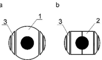
Figure 2. Milling and cutting of bars with core rot: a - bar with core rot; b - angle bars.
The yield of the bars of the angular cross-section from the round assortment is 20%. The yield of side unedged boards is 22.5%. The overall useful yield is 42.5%.
The bars are glued together in pairs and the work pieces obtained in the form of channels are glued together to form an I-beam (Figure 3). The beam has a height of 207 mm, a width of 196 mm, a belt thickness of 27 mm and a wall thickness of 43 mm (Figure 4).
Figure 3. Bonding of the angular profile bars into the I-beam: a - bars of angular profile; b - blocks glued to the channel; c - beam joined from channels.
Figure 4. Cross section of the beam.
3. Results and Discussion
The design scheme for determining strength and deflections of the beam is a statically determinate hinged beam, loaded with a uniformly distributed load. The design spacing of the structure is assumed to be 6 meters. Under the action of a load equal to 1.5 kN/m, the beam is exposed to stress-strain state of transverse bending. Strength characteristics of wood in two directions, adopted in accordance with SR 64.13330.2017 "Wooden structures” are given in the table. 1. Coefficients for determination of settlement resistance are specified in table. 2.
Table 1. Characteristics of wood.
Parameters Designation Units 2 grade/class К24
Calculated resistance to bending RA
m MPa 22.5
Calculated resistance to splitting across wood fibers RA90, d MPa 2.4
Average modulus of flexure for calculation of bending E0, mean GPa 11.0
Table 2. Coefficients for calculation.
Parameters Designation Quantity
Coefficient of long action of loading for strength characteristics of wood ml 0.66
Coefficient of long action of loading for elastic characteristics of wood ml, E 1.0
Coefficient of breed of wood mb 1.0
Coefficient of service conditions of designs mc 1.0
Coefficient of temperature mt 1.0
3.1. Rated Stress
Rate stresses in the beam is determined by a formula:
d m
M
σ =
R
W
≤ , (3)where M- maximum bending moment, kN·m; W- moment
of resistance of lower stretched belt, m3; Rdm - tolerable calculated resistance to bending for 2 grade.
Maximum bending moment determined by a formula:
2
q l
M=
, kN m
8
⋅ ⋅
, (4)
Tolerable calculated bending resistance is determined by formula:
d A
m m l i
R =R ⋅m ⋅
∏
m, (5)where RAm - calculated bending resistance of wood, MPa (table 1);
m
l - coefficient of long action of loading forstrength characteristics of wood (table 2);
∏
mi - coefficients of operating conditions of a design m , b mc,mt(table 2). Results of calculations of the normal tension arising in a beam and the allowed settlement resistance at a bend are given in table 3 and table 4.
Table 3. Rated stress arising in a beam when bending.
Parameters qd, kN/m l, m M, kN/m W, m3 Results of calculation, MPa
Rated stress arising in a beam when bending 1.5 6.0 6.75 0.0011 6.14
Table 4. Tolerable calculated resistance to bending.
Parameters RA
m, MPa m1 mb mc Results of calculation, MPa
Tolerable calculated resistance to bending 22.5 0.66 1.0 1.0 14.85
Comparison of values of normal tension in a beam and the allowed settlement resistance at a bend is given in figure 5. The analysis shows that the size of normal tension in a beam, arising at a bend under loading, is 41% of size of the allowed settlement resistance.
3.2. Beam Deflection
Deflection is calculated by a formula:
k 4
II
5q l
f=
384 E
I
⋅ ⋅
⋅
, (6)where qk - rated load, kN/m;
l
- beam span, m; IIE
- calculated modulus of elasticity of wood in calculation with regard to extreme conditions of 2nd group, GPa;I
- momentof inertia of the beam cross-section, m4.
Rated load equals 1.25 kN/m. Beam span is 6 m. Calculated modulus of flexure of wood in calculations with regard to extreme conditions of 2nd group is calculated by formula:
II
0, mean l i
E =E ⋅m ⋅
∏
m (7)where E0, mean- average modulus of flexure, GPa (table 1);
l, E
m
- index for elastic characteristics (table 2);∏
mi-product of indices of operating conditions m , b
m
c, mt(table 2).
Table 5. Rated deflection of a beam.
Parameters qk, kN/m l, m E
0, mean, GPa ml, E mb mc mt EII, GPa I, m4 Results, mm
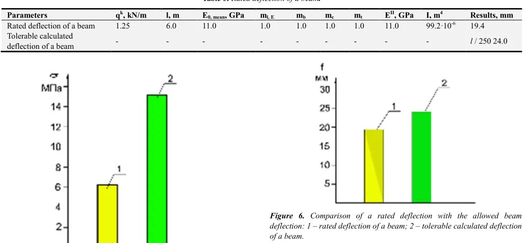
Rated deflection of a beam 1.25 6.0 11.0 1.0 1.0 1.0 1.0 11.0 99.2·10-6 19.4
Tolerable calculated
deflection of a beam - - - l / 250 24.0
Figure 5. Comparison of rated stress with tolerable calculated resistance to bending: 1 – the rated stress of in a beam when bending; 2 – the tolerable calculated resistance to bending.
Figure 6. Comparison of a rated deflection with the allowed beam deflection: 1 – rated deflection of a beam; 2 – tolerable calculated deflection of a beam.
80% of size of the allowed deflection. The deflection doesn't exceed the most admissible deflection.
3.3. Tangential Stress
Tangential stresses occur in the wall of the beam. The greatest value they arise in the supporting zones, where the transverse load reaches a maximum value. In connection with this, the beam shall be checked for shearing tangential stresses in the supporting zone.
Beam resistance to splitting is calculated by formula:
w
90, d
Q S
τ= R
I b⋅⋅ ≤ , (8)
where
Q
- calculated transverse force, kN; S- static moment of moving part of cross-section, m3; I- moment of inertia ofcross-section, m4; bw- wall thickness, m.
Tolerable calculated resistance to bending is determined by formula:
A
90, d l i
90, d
R =R ⋅m ⋅
∏
m , (9)where RA90, d- calculated resistance of wood to splitting along wood fibers, MPa (table 1); m - long-term resistance index l
(table 2);
∏
mi- product of indices of operating conditions,b
m , mc, mt (table 2).
Results of calculation of tangent tension and the allowed settlement resistance are given in table 6 and 7.
Table 6. Tangent tension in a beam.
Parameters qd, kN/m l, m Q, kN S. m4 I, m4 b
w, m Results, MPa
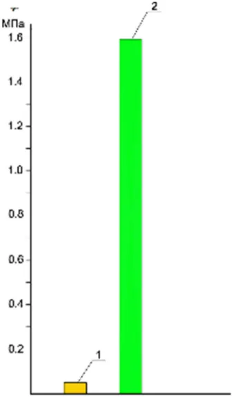
Tangent tension in a beam 1.5 6.0 4.5 4.9 10-3 99.2 10-6 0.043 0.05
Table 7. Tolerable calculated tangent tension in a beam.
Parameters RA90, d, MPa ml mb mc mt Results, MPa
Tolerable calculated tangent tension in a beam 2.4 0.66 1.0 1.0 1.0 1.58
Comparison of size of tangent tension and the tolerable calculated tangent tension in a beam is given in figure 7. The analysis shows that the size of the tangent tension arising at a bend under loading is only 3% of size of the allowed tolerable calculated tangent tension in a beam.
Figure 7. Comparison of tangent tension with the tolerable calculated tangent tension in a beam: 1 – tangent tension in a beam at a bend; 2 – the tolerable calculated tangent tension in a beam.
4. Conclusions
Analyzing the received results it is possible to draw the following conclusions:
1. It is possible to apply the double-T section beams received from round forest products with a core decay as the bearing building constructions.
2. Settlement characteristics of the beams which are stuck together from angular elements correspond to operational loadings.
3. The actual tension in beams received as a result of calculations 1.25-2.5 times less allowed.
4. It is possible to use results of researches when developing the specifications and technical documentation of requirements to the bearing building constructions.
3. Use of round forest products with core decay expands wood resources for construction.
However, the method of calculations accepted in work doesn't consider anisotropic properties of wood of a beam. More exact decision on strength characteristics of I-beams from angular elements requires carrying out further researches and including tests of beams.
References
[1] N. A. Vorontchova, N. V. Filatov, Ye. G. Shestopalov, “Use of glued plywood elements with perforated walls in the construction of low wooden buildings”, vol. 80, Vologda readings, 2012, pp. 74-76.
[3] A. V. Sintshov, V. P. Sintshov. “Strength and deformability of a composite wooden beam with a wall of oriented particile board”, vol. 50, Building and technogenic security, 2014, pp. 152-158.
[4] O. A. Mikhaylenko, M. S. Kozhevnikova, “On the influence of anisotropy of the elastic properties of wood and plywood on the stress-strain state of combined structures”, Technical sciences - from theory to practice: collection of articles, LXIII International Scientific-Practical Conference, vol. 10 (58), Novosibirsk: SibAK, 2016, pp. 118-126.
[5] A. V. Karelsky, T. P. Zhuravleva, B. V. Labudin, “The test for the bending of wooden composite beams connected by metal toothed plates, destroying the load”, vol. 2(54), Magazine of Civil Engineering, 2015, pp. 77-127.
[6] Benjeddou Omrane, Limam Oualid, Ouezdou Mongi Ben, “Experimental and theoretical study of a foldable composite beam”, vol. 44, Engineering and Structures, 2012, pp. 312-321.
[7] Challamel Noël, Girhammar Ulf Arne, “Lateral-torsional buckling of vertically layered composite beams with interlayer slip under uniform moment”, vol. 34, Engineering and Structures, 2012, pp. 505—513.
[8] P. M. Davis, R. Gupta, A. Sinha, “Revisiting the neutral axis in wood beams”, Holzforschung, 2012, pp. 497-503.
[9] Fernando D., Frangi A., Kobel P., “Behavior of basalt fiber reinforced polymer strengthened timber laminates under tensile load”, vol. 117, Engineering and Structures. 2016, pp. 437-456.
[10] Harte A. M., Baylor G., “Structural evaluation of castellated timber I-joists”, vol. 33, no. 12, Engineering and Structures, 2011, pp. 3748-3754.
[11] Hu Chuanshuang, Xiao Min, Zhou Haibin, Wen Wei, Yun Hong., “Damage detection of wood beams using the differences in local modal flexibility”, vol. 57, no. 6, J. Wood Science, 2011, pp. 479-483.
[12] L. V. Lyutov, “The use of composite combined beams in the construction of low-rise wooden houses”, vol. 15, no. 5, MOTROL, 2013, pp. 151-156.
[13] V. P. Sintsov, L. V. Liutov, “Experimental study of nailed connections of wooden bars with a thin steel plate”, vol. 6, Construction mechanics of engineering structures and structures, 2015, pp. 16-20.
[14] E. Toussaint, E. Fournely, Pitti R. Mountou, M. Gredias. “Studying the mechanical behavior of notched wood beams using full-field measurements”, vol. 113, Engineering and Structures, 2016, pp. 277-286.
[15] I. L. Kuznetsov, I. V. Krainov, L. R. Gimranov, “Strengthening of glued plywood I-beams”, vol. 4, Izvestiya of Kazan State Architectural and Construction University, 2015, pp. 166-170. [16] A. N. Ponomarev, A. S. Rassokhin, “Hybrid wood-polymer
composites in civil engineering”, vol. 8(68), Magazine of Civil Engineering, 2016, pp. 45-47.
[17] A. R. Tusnin, M. Prokitch, “Pilot studies of work of beams of double-T section at action of a bend and torsion”, vol. 1(53), Magazine of Civil Engineering, 2015, pp. 24-31.
[18] A. S. Toropov, S. A. Toropov, E. V. Mikryukova, “Investigation of the damage of wood with rotted decay”, vol. 4, IVUZ Lesnoy zhurnal, 2009, pp. 95-100.
[19] V. F. Dunaev, “Sawmill: from geometry to physics, mechanics and technology”, vol. 1, IVUZ Lesnoy zhurnal, 2008, pp. 90-100.