[Shather * et al., 6(2): February, 2019]
ISSN: 2349-5197
Impact Factor: 3.765
I
NTERNATIONAL
J
OURNAL OF
R
ESEARCH
S
CIENCE &
M
ANAGEMENT
PREDICTION OF SURFACE ROUGHNESS AND METAL REMOVAL RATE INTO
MAGNETIC ABRASIVE FINISHING FOR SILICON CARBIDE ABRASIVE
Assist. Prof .Dr. Saad Kariem Shather
*1& Muhamed Abdal-khadim Abd Alaqeeli
2University of Technology, Department of Production Engineering & Metallurgy, Iraq, Baghdad
DOI: 10.5281/zenodo.2560470
Abstract
Magnetic abrasive finishing (MAF) is one of advanced method which play a major role in important applications ( medical, rocket and aerospace parts , dies) .this paper was focused intoprediction of surface roughness and metal removal rate during intervening important parameters (mesh size ,concentration,gap between workpiece and poles).experiments show thatthe best surface roughness can be obtained when machining workpiece of low carbon steel by silicon carbide (Sic) was 0.007µm at concentration 33% SiC and maximum metal removal rate can be obtained 0.004gm at concentration ( 25% SiC and 75% Fe) the Minitab software version 17 was used to predict the surface roughness and metal removal rate which obtained good result and agreement with experimental values for surface roughness and metal removal rate when comparing between them reach to 98.66%.
Introduction
Finishing is among latest processes which are performed on the workpiece to achieve surface quality and dimensions. Magnetic Abrasive Finishing (MAF) process is one of important machining process mainly used to achieve surface finish by using magnetic poles ,usually (MAF) was finishing process used to enhance the surface layer and abrasive particles play important role in machining .the workpiece is kept between two poles and there is a gap filled with powder consist of abrasive from (SiC,Al2O3,B4C,TiC ….etc) mixed with Iron powder .S.C. [1] .
In MAF process , the workpiece is kept between the two poles of a magnet and the working gap between the workpiece and the magnet is filled with magnetic abrasive particles composed of ferromagnetic particles and abrasive powder.[2,3]
S. C. JAYSWA Letal ( 2005) study the effect of flux density , height of working gap, size of magnetic abrasive particles on magnetic abrasive finishing process with their effect on surface roughness and concluded that surface roughness value (Rmax) of the workpiece decreases with increase in flux density and size of magnetic abrasive particles. Surface roughness value (Rmax) decreases with decrease in working gap. Rmax value also decreases when the magnet has a slot as compared to the magnet having no slot. [4,5]
Saadkariem Shatheretal (2015) study the technological parameters (current ,working gap , abrasive in magnetic abrasive finishing (MAF) with regression analysis of variance (ANOVA) and concluded that the amplitude of pole geometry has significant effect on the surface roughness (Ra) which improved the surface roughness about 30% [6]
Jiang Guoetal (2017) study the influence of two types of abrasive (SiC,Al2O3) on MAF process size on polishing force and MRR, wear of magnetic abrasives, surface roughness and surface morphologies obtained using different types of magnetic abrasives ,experiments prove that higher MRR and low surface roughness by using SiC and smooth surface by Al2O3.[7,8]
[Shather * et al., 6(2): February, 2019]
ISSN: 2349-5197
Impact Factor: 3.765
I
NTERNATIONAL
J
OURNAL OF
R
ESEARCH
S
CIENCE &
M
ANAGEMENT
installation on the flat area of the magnets as well as magnets’ spark in curve this condition can improve surface roughness up to 75% based on simulation results. In performed experiments, based on the ranges of the variables, improvement was reported up to 62%. Difference was 13% percent, which is acceptable [9,10]
Saad Kariem Shatheretal (2019) focused on the effect of mesh size and concentration ,gap dimension of abrasive of silicon carbide when added to Iron powder , they concluded that there are great influence on surface roughness and metal removal rate.[11]
Analysis of Application SiC Abrasives on surface roughness (Ra)
The analyses of application abrasive SiC on surface roughness ( Ra) are listed in Table (2)In the present work regression model has been developed and experimental results obtained were subject to analysis by using MINITAB-17 statistical software to evaluate the relationship between input and output process parameters. Based on the experimental findings of 12 runs the following regression models have been evolved a Regression Equation for surface roughness is given by
Eq (1) Ra (µm ) = 0.088 + 0.00591 *wt% - 0.000348* mesh - 0.02033 *gap (mm) - 0.000152 (wt %)² ……… (1)
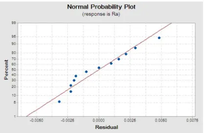
Where (R-sq) of regression model gets (98.66%) that represent our model better fits the data. More the value of R-sq, better the model fits our data and prediction of response is more accurate. The normal distribution probabilities for (Ra) to SiC-Fe abrasive powder is shown in Figure (3) .experimental procedure involve many steps to achieve experiments and usually started with preparing the powder of magnetic abrasive of silicon carbide ( Sic) which mixed with glass binder or resin to machine work piece from low carbon steel which has the chemical composition as shown in table (1) at different percentage of abrasives (25,30,33% of SiC) mixed together with powder of Fe Then ,cutting conditions were used (abrasive concentration, mesh size , gap dimension ) which can be shown in tables,(2, 3)
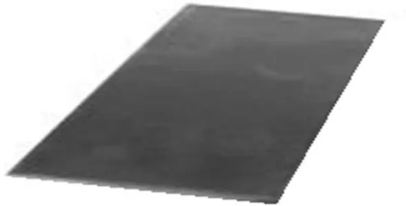
The work piece dimension ( 4 x 60 x 100 mm) was usedin experiments with the chemical composition as shown in table (1)
Figure (1) workpice
Table (1) chemical composition of workpiece
W% V%
Ti% Cu% Co%
Al% Ni%
Mo% Cr% S%
P% Mn % Si% C %
[Shather * et al., 6(2): February, 2019]
ISSN: 2349-5197
Impact Factor: 3.765
I
NTERNATIONAL
J
OURNAL OF
R
ESEARCH
S
CIENCE &
M
ANAGEMENT
Silicon carbide:Silicon Carbide (SiC) is the only chemical compound of carbon and silicon. It was originally produced by a high temperature electro-chemical reaction of sand and carbon. Silicon carbide shown in Figure (2) is an excellent abrasive material. It has Low density, High strength, Low thermal expansion, High thermal conductivity, High hardness, excellent thermal shock resistance was used in experiments with different concentration ( 25% ,30%,33%) mixed with iron powder concentration 75% ,70% ,67% then added binder to the mixture and put into furnace at 250C° sintering process.
Figure (2) Abrasive of silicon carbide
[Shather * et al., 6(2): February, 2019]
ISSN: 2349-5197
Impact Factor: 3.765
I
NTERNATIONAL
J
OURNAL OF
R
ESEARCH
S
CIENCE &
M
ANAGEMENT
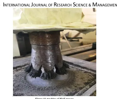
.
Figure (4) machine of MAF process
Table (2) Theoretical and experimental Values of surface roughness at different concentration of SiC abrasive, mesh size
and working gap for workoiece
Theoretical Surface roughness (Ra) Surface roughness
(Ra) after
machining,µm Surface
roughness (Ra) before
machining, µm Gap,mm
Mesh size Concentration of SiC
abrasive % No 0.075 0.073 0.166 1.5 100 SiC 25% - Fe 75%
1- 0.065 0.068 0.170 2 100 SiC 25% - Fe 75%
2- 0.040 0.042 0.126 1.5 200 SiC 25% - Fe 75%
3- 0.030 0.028 0.146 2 200 SiC 25% - Fe 75%
4- 0.063 0.061 0.161 1.5 100 SiC 30% - Fe 70%
5- 0.052 0.051 0.135 2 100 SiC 30% - Fe 70%
6- 0.028 0.033 0.173 1.5 200 SiC 30% - Fe 70%
7- 0.018 0.017 0.132 2 200 SiC 30% - Fe 70%
8- 0.052 0.053 0.144 1.5 100 SiC 33% - Fe 67%
9- 0.041 0.044 0.121 2 100 SiC 33% - Fe 67%
10- 0.017 0.014 0.133 1.5 200 SiC 33% - Fe 67%
11- 0.008 0.007 0.162 2 200 SiC 33% - Fe 67%
12-
[Shather * et al., 6(2): February, 2019]
ISSN: 2349-5197
Impact Factor: 3.765
I
NTERNATIONAL
J
OURNAL OF
R
ESEARCH
S
CIENCE &
M
ANAGEMENT
Figure (5)Comparison between Experimental and Theoretical Ra Data for SiC- Fe abrasive brush
Analysis of Application SiC Abrasives on MRR
The analyses of application SiC on MRR are shown in table (3)andValues of MRR for different wt% of SiC abrasive, mesh size and working gap on (ASTM 415) low carbon steel Based on the experimental findings of 12 runs the following regression models have been evolved
MRR (gm/min) = 0.00427 + 0.000317 wt% - 0.000012 mesh -0.001845 gap - 0.000006 (wt %)²…….(2)
[Shather * et al., 6(2): February, 2019]
ISSN: 2349-5197
Impact Factor: 3.765
I
NTERNATIONAL
J
OURNAL OF
R
ESEARCH
S
CIENCE &
M
ANAGEMENT
Figure (6 )Plot of normal distribution probability for (MRR) to SiC-Fe abrasive powder
As a result of the comparing between the experimental and theoretical MRR result, the Figure (7) below showed that there is an approach in data between them.
[Shather * et al., 6(2): February, 2019]
ISSN: 2349-5197
Impact Factor: 3.765
I
NTERNATIONAL
J
OURNAL OF
R
ESEARCH
S
CIENCE &
M
ANAGEMENT
Table (3) Theoretical and experimental Values of metal removal at different concentration of SiC abrasive, mesh size and working gap for work piece
Theoretica l MRR ExperimentalMRRgm/mi
n
Wt% after
machining,(gm ) Wt% before Machining(gm ) Gap ,m m Mes h Concentratio
n of SiC
abrasive No 0.0044 0.0042 175.03 175.158 1.5 100 SiC 25% - Fe 75% 1- 0.0033 0.0032 197.32 197.417 2 100 SiC 25% - Fe 75% 2- 0.0030 0.0030 194.09 194.182 1.5 200 SiC 25% - Fe 75% 3- 0.0021 0.0022 192.24 92.306 2 200 SiC 25% - Fe 75% 4- 0.0040 0.0041 165.39 165.515 1.5 100 SiC 25% - Fe 75% 5- 0.0031 0.0031 185.42 185.513 2 100 SiC 25% - Fe 75% 6- 0.0028 0.0027 172.01 172.093 1.5 200 SiC 25% - Fe 75% 7- 0.0019 0.0020 185.52 185.581 2 200 SiC 25% - Fe 75% 8- 0.0038 0.0039 176.61 176.727 1.5 100 SiC 33% - Fe 67% 9- 0.0027 0.0028 182.33 182.414 2 100 SiC 33% - Fe 67% 10 - 0.0026 0.0025 176.38 176.456 1.5 200 SiC 33% - Fe 67% 11 - 0.0017 0.0018 174.97 175.024 2 200 SiC 33% - Fe 67% 12
-
Surface roughness device: surface roughness device was used to measure the surface roughness (Ra) of machined surface shown in Figure (8).
[Shather * et al., 6(2): February, 2019]
ISSN: 2349-5197
Impact Factor: 3.765
I
NTERNATIONAL
J
OURNAL OF
R
ESEARCH
S
CIENCE &
M
ANAGEMENT
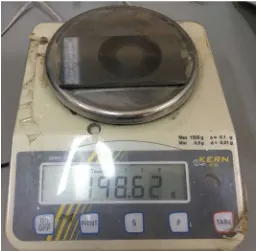
Weighting device: this device was used toweighed theworkpiece before and after machining by using MAF process.
Figure (9) device for weight
Result and discussion
According to tables ( 2,3 ) concluded that the maximum value of surface roughness was 0.073µm at concentration of abrasive 25 % Si and 75% Fe with gap 1.5mm, mesh size 100 while minimum surface roughness can be obtained 0.007µm at concentration 33% Si which related with mesh size and concentration of SiC abrasives and 67% Fe with gap 2mm , mesh size 200 and for metal removal rate maximum MRR was 0.004gm at concentration 25% Si and 75% Fe with gap 1.5mm,mesh size 100 and minimum metal removal rate was 0.0017gm at concentration 33% Si and 67% Fe ,gap 2 and mesh 200mm. Figure (6,7) show the maximum surface roughness at concentration 25% Si and the concentration 30% ,33% while Figure (9,10) gaps 1.5mm and concentration 25% ,30% causes rise of surface roughness more than ( 0.05 ,0.06 µm) and minimum surface roughness obtained at mesh 200 from 0.01-0.04µm so the value of metal removal rate while the maximum metal removal rate was at point 0.004gm and minimum was 0.002gm at concentration 33% and mesh 200.
Conclusions
From experiments and values of surface roughness and metal removal rate above can be concluded the following conclusions:
1. The mesh size and concentration of silicon carbide ( SiC) abrasives have great significant on surface roughness and metal removal rate.
2. Also gap dimension between work piece and magnet has an effect
3. Minitab software 17 give good result for prediction the surface roughness and metal removal rate.
4. More than 98% percent agreement between experimental and theoretical values for surface roughness
[Shather * et al., 6(2): February, 2019]
ISSN: 2349-5197
Impact Factor: 3.765
I
NTERNATIONAL
J
OURNAL OF
R
ESEARCH
S
CIENCE &
M
ANAGEMENT
References
[1] Jayswal • V.K. Jain • P.M. Dixit"Modeling and simulation of magnetic abrasive finishing process" Int J AdvManufTechnol (2005).
[2] G.Z.Kremen,E.A.Elsayed&V.I.Rafalovich "Mechanism of material removal in the magnetic abrasive process and the accuracy of machining"Pages 2629-2638 .06 Apr 2007.
[3] Nitaigour P. Mahalik" Micro manufacturing and nanotechnology "Springer Book , 2010.
[4] Sehijpal Singh Khangura ,ParamjitSingh,Harwider Singh ,GurinderSingh."Proceedings of the
international conference on research and innovations in mechanical engineering 2013.
[5] Kheelan B. Patel and Dr. K M Patel" Magnetic Abrasive Finishing of AISI52100" International Journal of Trend in Research and Development.Vol 1. 2014.
[6] Saadkariem Shather, Shakir .M.Mousa."The influence of design and technological parameters on the MAF process" Al Kawarizmi Engineering Journal .vol. 11, No. 4, P.P. 82- 88.2015.,
[7] V.K.Jain "Nano finishing science and technology" basic and advanced finishing and polishing processes, Book,2016
[8] Jiang Guo , ZhiEn Eddie TanKaHingAuKui Liu "Experimental investigation into the effect of abrasive
and force conditions in magnetic field-assisted finishing "The International Journal of Advanced Manufacturing Technology. Volume 90, Issue 5–8, pp 1881–1888.May 2017.
[9] Mehrdad Vahdati and Seyed Alireza Rasouli” Evaluation of Parameters Affecting Magnetic Abrasive Finishing on Concave Freeform Surface of Al Alloy via RSM Method” Hindawi Publishing Corporation Advances in Materials Science and Engineering, Volume 2016, Article ID 5256347, 14 pages.
[10] LaRoux K. Gillespie "Design for advanced manufacturing " Book,2017.
[11] Amardeep Singha, Sehijpal Singhb, Lakhvir Singh "Comprehensive Review Of Current Research Trends
In Magnetic Abrasive Finishing (MAF) Process" Advanced Materials Manufacturing & Characterization) Vol. 8 Issue 1 (2018).
[12] Saad Kariem Shather , MuhamedAbd-Alkhadim Abd Alaqeeli “Influence of silicon carbide (SiC)