Optimization of the Accelerators for the ITER Neutral Beam
Injector Project
Vanni ANTONI, Piero AGOSTINETTI, Marco CAVENAGO
1), Hubert P. L. DE ESCH
2),
Gwenael FUBIANI
3), Nicola PILAN, Gianluigi SERIANNI, Pierluigi VELTRI,
Mieko KASHIWAGI
4), Masaki TANIGUCHI
4), Naotaka UMEDA
4), Takashi INOUE
4)and NBI RFX TEAM
Consorzio RFX Euratom-ENEA Association, Padova, 35126, Italy
1)INFN-LNL, Legnaro, 35020, Italy
2)Association EURATOM-CEA Cadarache, IRFM/SCCP, St. Paul Les Durance, 13108, France 3)LAPLACE/CNRS, University Paul Sabatier, Toulouse, 31062, France
4)Japan Atomic Energy Agency, Naka, 311-0193, Japan
(Received 2 February 2009/Accepted 21 June 2009)
A joint Japan-EU R&D activity is in progress to optimize the accelerator for the ITER NBI. The accelerator baseline design is based on a five grids system which can be adapted to operate with three grids for initial operations at low voltage (500 kV). Moreover, in order to speed up the test of the NBI system at the Test Facility, a negative ion source with extraction voltage up to 100 kV will be operated in parallel to the full injector. In this contribution the three accelerators mentioned above are presented discussing the procedure to optimize the grid geometry in order to assure optimum optics during operation when the grids undergo deformations and thermal stresses due to the particles that hit their surface.
c
2010 The Japan Society of Plasma Science and Nuclear Fusion Research
Keywords: ITER, heating and current drive, negative ion acceleration DOI: 10.1585/pfr.5.S1014
1. Introduction
Two Neutral Beam Injectors (NBI) are foreseen in ITER in order to deliver a total of 33 MW of heating power. Each NBI is designed to operate at 1 MV and 40 A current in Deuterium and at 870 kV and 46 A in Hydro-gen [1, 2]. In recent years a joint revision of the NBI de-sign for ITER performed by the Japan and EU Domestic Agencies in close contact with ITER has led to important changes which have improved the availability and reliabil-ity of the NBI system [3]. The insertion of an absolute gate valve between the NBI and the duct and the modifi-cation of the Beam Line Vessel with possibility of vertical access, have improved the availability of the system while shortening the time required for maintenance and repair in case of fault. The adoption of the air insulated High Voltage deck and the choice of the RF Ion Source have led to less demanding maintenance for the source which does not require replacements of the filaments as it was for the arc driven source. Passive and active protection sys-tems for the accelerator grids and power supplies are now implemented in the project therefore improving the relia-bility of the system. Finally the design of the Test Facil-ity to be built in Padova and aimed to test and optimize the NBI and to assist the operations in ITER has been al-most completed [4]. A robust R&D program is in progress author’s e-mail: [email protected]
at the 1 MV test facilities in Naka (JAEA) and Cadarache (CEA) to tackle and solve the remaining issues related to high voltage holding and particle acceleration in the 1 MV range [5–7]. To assess a multi-aperture multi-grid (MA-MuG) and a single-aperture single-gap (SINGAP) accel-erator [8] concepts at the same test facility with the same diagnostics, a collaborative R&D was performed between JAEA and CEA Cadarache under an ITER task agreement. As a result of better voltage holding and less electron ac-celeration, the MAMuG was confirmed as the baseline de-sign for ITER [5–7]. All these activities have led to a better understanding of the physics of the 1 MV accelerator and of the negative ion extraction which have allowed the ac-celerator design to be further advanced as discussed in the following.
2. The Accelerator Design
In the ITER NBI baseline design the accelerator is a MAMuG system based on five grids [9]. In order to provide auxiliary heating to the initial operation of ITER in Hydrogen and relatively low current, it has been pro-posed to operate one of the NBI as a three grid system at a reduced voltage of 500 kV. It has been verified that the present grid support structure and power supply layout can easily be adapted to a three grids system. In this con-tribution three accelerators of interest for ITER, namely
c
2010 The Japan Society of Plasma
the five-grids 1 MV accelerator in the reference design, the three-grids 500 kV accelerator foreseen for initial opera-tions and the single grid 100 kV accelerator to optimize the extraction in the Ion Source are presented. The criteria and the method applied to optimize the accelerator design are described. In particular the design of the accelerator grids has to provide optimum perveance, compatible with the finite size of the grids due to the cooling channels and the insertion of permanent magnets required to deflect the unwanted electrons co-extracted from the source or gener-ated by stripping losses. The thermo-mechanical analysis of the grids has been performed by taking into account the power load due to co-extracted and secondary electrons. In order to minimize the grid bending and the thermal stresses the grids are actively cooled and the cooling channels have been carefully designed in order to be accommodated in a relatively narrow space.
The optimization process is therefore based on a se-quence of the following steps which are reiterated up to final convergence:
a) The initial electric field distribution is computed. b) The magnetic field distribution as obtained from the
combination of magnetic filter and permanent mag-nets inserted in the grids is added.
c) The particle trajectory is computed.
d) The interaction with the background gas is simulated by evaluating the stripping losses and the generation of secondary particles due to interaction of primary particles with material surfaces.
e) The new electric field distribution due to the charge distribution and the related trajectories are calculated up to convergence.
f) The thermal load due to ions and electrons intercept-ing the grids is evaluated and the deformation, when the cooling is applied, evaluated. The design of the grids (cooling channels size and layout and position of permanent magnets) is modified in order to mini-mize the deformation.
g) Steps from a) to f) are repeated until an optimum con-figuration is obtained for a single or a couple of beam-lets.
h) Interaction among beamlets is evaluated to compen-sate for the divergence of the beamlets by a suitable mechanical displacement of the apertures.
These steps are accomplished using different codes. The electric field and the initial trajectories are computed by using the code SLACCAD [10, 11] and then by adding the magnetic field distribution. Recently a new code BYPO [12], which solves in a self-consistent way the trajecto-ries with an initial distribution of magnetic and electric field, has been developed and the results applied to bench-mark the results of SLACCAD. The interaction of the par-ticles with background gas and material surfaces are de-scribed by the Monte Carlo Code EAMCC [13]. The ther-mal analyses are performed by using ANSYS. Finally the
Fig. 1 Ion beam trajectories simulated with SLACCAD. Also the aperture profiles and the magnetic field by suppres-sion magnets is sketched.
beamlet-beamlet interaction is studied by using the code OPERA [14]. This procedure has been applied to the op-timization of the highest priority accelerator, namely the low voltage one, as in the present planning it is expected to enter into operation in three years from approval. This accelerator shares several characteristics with the acceler-ator required by the diagnostic neutral beam (DNB) [9] for operation in Hydrogen, so that the initial development of the accelerator has been performed in parallel with that of the DNB. The main requirements of this accelerator are a current of 60 A H−(and later 40 A D−) and an energy of 100 keV. In Fig. 1 a comparison of the beam profile for the three accelerators is shown.
3. Study of the Beam Optics
All three accelerators work with multi-aperture grids biased at different potentials. Each grid features 1280 aper-tures. All systems have a Plasma Grid (PG) and an Extrac-tion Grid (EG - at approximately 10 kV). The acceleraExtrac-tions steps are respectively:
• 5 acceleration grids for ITER MAMuG (5 accelera-tion steps of 200 kV each)
• 3 acceleration grids for ITER Half-Voltage (3 accel-eration steps of about 160 kV)
• 1 acceleration grid for SPIDER (a single acceleration step of 90 kV)
macropar-Fig. 2 Scheme of the grids for the 100 kV accelerator: (a) De-sign overview; (b) Detailed view of the grids.
Fig. 3 SLACCAD simulation of the beam optics: equipotential lines (blue) and particle trajectories (magenta) are esti-mated by integration of the Poisson’s equation.
ticle represents an ensemble of rays. This code needs as inputs the electric and magnetic fields inside the acceler-ator. The former was calculated with SLACCAD, as ex-plained above. The latter was calculated by summing the field given by the SmCo permanent magnets and the field from the plasma grid filter current (calculated by assuming an infinitely thin electron sheath). Collisions are described using a Monte-Carlo method. The various kinds of colli-sions considered in the code are: (i) electron and heavy ion/neutral collisions with grids, (ii) negative ion single and double stripping reactions and (iii) ionization of back-ground gas.
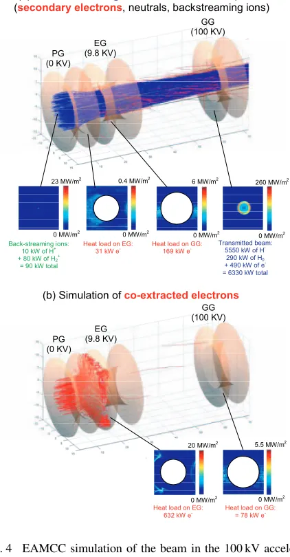
In Fig. 4 the trajectories of negative ions and of co-extracted and stripping loss electrons for a single
beam-Fig. 4 EAMCC simulation of the beam in the 100 kV acceler-ator: the particle trajectories and stripping reaction are simulated with a Monte Carlo approach in a domain with electrical and magnetic fields. The power corresponding to the whole accelerator (1280 beamlets) is reported.
let are shown. The corresponding thermal load is also shown [15]. The PG is heated by the plasma inside the RF ion source, with a surface power density that is estimated to be about 20 kW m−2[16]. This grid is required to
Suppres-sion magnets, embedded in the grid, have the function to deviate the trajectories of the co-extracted electrons, mak-ing them collide with the grid surface. The consequent power loads are quite high and concentrated, hence this grid is the most critical from the structural point of view, and is designed with a high performance cooling system. The grounded grid (GG) has the function to accelerate the ion beamlets up to a potential of about 100 kV, and is also loaded by co-extracted and stripping electrons.
While the EG is heated mostly by the co-extracted electrons, the heat on the GG is approximately half com-ing from the co-extracted electrons, and half from the sec-ondary electrons due to stripping and surface reactions.
The transmitted beamlet power distribution features a ring that is hotter than the central part. These could be due to the chamfered shape of the PG apertures. In fact, this effect is reversed in case of a flat PG surface [15].
The backstreaming positive ions are concentrated in the center of the aperture area. The consequent heat power density is quite high, as it covers only an area of some tens of square millimeters. These ions could give rise to sputtering phenomena on the plasma source back plate and on the driver Faraday shields, with a consequent decay of the plasma purity and problems of surface integrity. The sputtering yield due to the backstreaming deuterium ions is generally reduced by a factor of about 5 if the copper surface is coated with Molybdenum. Hence, in order to minimize the detrimental effects consequent to sputtering, a layer of Molybdenum of some microns is foreseen to be applied on the plasma source back plate.
4. Thermo-Mechanical Optimization
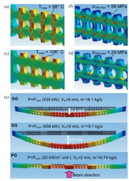
The grids must be designed in such a way that the cor-responding apertures are well aligned during all the operat-ing scenarios, in order to obtain good beam optics. For this reason and for manufacturing requirements they are verti-cally split in four segments, independently supported with a fixed pin at the left side and with a sliding pin at the right side [18]. For optical reasons, the maximum allowable misalignment between the corresponding apertures of the three grids is fixed to 0.4 mm, whose 0.2 mm due to ther-mal expansion. The grids have also to withstand two cate-gories of stresses: a) Cyclic thermal stress due to the tem-perature gradients between hotter and colder zones. These stresses must be maintained low in order to satisfy the re-quirement on fatigue life. b) Static stress due to the wa-ter pressure. The local values of equivalent stress must be lower than the allowable values for electrodeposited cop-per (fixed at 100 MPa). The position and dimensions of the cooling channels, as well as the water flow, must be opti-mized in order to satisfy all the requirements on alignment and stresses according to the ITER criteria [19] and in all scenarios (conditioning, partial power, full power etc.).Several analyses have been performed to estimate the temperatures and stresses along the grids [20]. Fig. 5
Fig. 5 Thermo-structural analyses performed with the ANSYS code on the reference scenario: (a) and (b) Temperature and Von Mises equivalent stress on the EG; (c) and (d) Temperature and Von Mises equivalent stress on the GG; (e) Out of plane deformations of the three grids.
shows the results for the reference operating conditions at 100 kV. It appears that the thermal stresses are causing also an out-of-plane deformation of the grids. The analy-ses have shown that these deformations can be minimized in order to keep within tolerable values the increase in the beam divergence.
5. Compensation of Beamlet
Repul-sion
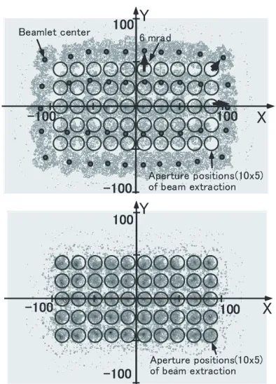
Fig. 6 Calculated beam footprints at 3.5 m downstream from the GRG (a) before and (b) after proper aperture offset in the extractor. The beam parameter is 110 A/m2 of D−
ion beam current density and 340 keV at beam energy. Opened circles represent the original aperture positions.
proper aperture offset at the bottom of extractor. The re-sults have shown that a proper aperture offset within 1 mm is enough to correct the beamlet deflection by the beamlet-beamlet interaction. This compensation techniques is to be applied to design 100 kV, 500 kV and 1 MeV accelerators.
6. Conclusions
The better understanding of the physics and the nu-merical tools available allow the optimisation of the accel-erators for ITER to be carried out.
The procedure to optimize the 100 kV accelerator for ITER has been described with the present design of the accelerator. Using this procedure, the design of the extrac-tion and acceleraextrac-tion system for the ITER NBI and related experiments can been accomplished by taking into account at the same time physics and engineering requirements.
Acknowledgements
The work performed by Consorzio RFX was set up in collaboration and financial support of Fusion for energy.
[1] R.S. Hemsworthet al., Rev. Sci. Instrum.67, Issue 3, 1120 (1996).
[2] T. Inoueet al., Fusion Eng. Des.56-57, 517 (2001). [3] R.S. Hemsworth et al., Rev. Sci. Instrum. 79, 02C109
(2008).
[4] P. Sonatoet al., 25th Symposium on Fusion Technology, 15-19 September 2008, Rostock, Germany.
[5] M. Taniguchiet al., AIP Conf. Proc.1097, 335 (2009). [6] H.P.L De Esch et al., Fusion Eng. Des.84, 669 (2009);
G. Fubianiet al.Phys. Rev. Special Topics, Accelerator and Beams12, 050102 (2009).
[7] M. Kashiwagiet al., to be published in Nucl. Fusion. [8] H.P.L. de Esch, R.S. Hemsworth and P. Massmann. Fusion
Eng. Des.73, 329 (2005).
[9] ITER Technical Basis 2002, Detailed Design Document (section 5.3 DDD5.3) (Vienna: IAEA).
[10] J. Pamela, Rev. Sci. Instrum.62, 1163 (1991).
[11] W.B. Hermannsfeld, Electron Trajectory Program, SLAC report, Stanford Linear Accelerator Center, SLAC-226 (1979).
[12] M. Cavenago et al., IEEE Trans. Plasma Sci. 36, 1581 (2008).
[13] G. Fubianiet al., Phys. Rev. Special Topics Accelerators and Beams11, 014202 (2008).
[14] “OPERA-3d”, Vector Fields Co.Ltd., http://www. vectorfields.com/
[15] P. Agostinetti et al., Proceedings of the 1st International Conference on Negative Ions, Beams and Sources, 2008, Aix en Provence, France.
[16] P. Agostinetti, S. Dal Bello, M. Dalla Palma, D. Marcuzzi, P. Zaccaria, R. Nocentini, M. Frschle, B. Heinemann and R. Riedl, 22nd IEEE/NPSS Symposium on Fusion Engi-neering, Albuquerque, New Mexico, 2007.
[17] E. Spethet al., Nucl. Fusion46, S220 (2006).
[18] D. Marcuzziet al., 25th Symposium on Fusion Technology, 15-19 September 2008, Rostock, Germany.
[19] Various Authors, ITER MPH. Material Properties Hand-book. ITER Document No.G 74 MA 16.
[20] P. Agostinetti, S. Dal Bello, M. Dalla Palma and P. Zac-caria, Fusion Eng. Des.82, 860 (2007).
[21] M. Kashiwagi et al., to be published in Conf. Proc. of American Inst. Phys. 2008.