Published online March 30, 2014 (http://www.sciencepublishinggroup.com/j/ajce) doi: 10.11648/j.ajce.20140202.15
An overview on the seismic design of braced frames
Muhammad Tayyab Naqash
1, Khalid Mahmood
2, Salim Khoso
31
Department of Civil Engineering, IQRA National University, Peshawar, Pakistan
2
Department of Civil Engineering, Comsats Institute of Information Technology, Abbottabad, Pakistan
3
Department of Civil Engineering, QUCEST, Larkana, Sindh, Pakistan
Email address:
[email protected] (M. T. Naqash)
To cite this article:
Muhammad Tayyab Naqash, Khalid Mahmood, Salim Khoso. An Overview on the Seismic Design of Braced Frames. American Journal
of Civil Engineering. Vol. 2, No. 2, 2014, pp. 41-47. doi: 10.11648/j.ajce.20140202.15
Abstract:
Seismic design of steel braced frames in the modern building codes follow the capacity design approach where some of the members are obliged to dissipate energy whereas others are taken care to be protected. In this paper the seismic design methodologies used by European and American approaches for Concentric Cross Braced Frames (CCBF) and Eccentric Braced Frames (EBF) are highlighted. Synoptic tables for the design of such frames of the most advance seismic codes i.e., Eurocode 8 and the seismic provisions of American Institute of Steel Construction (AISC) are provided. Emphasizes are made on the provisions of Eurocode 8 both for CCBF and EBF. Finally, a general conclusion is drawn when dealing with CCBF and EBF.Keywords:
Steel Brace Frames, Capacity Design, Cross Bracing, Eccentric Bracing, Seismic Design1. Introduction
Wide range of special seismic design requirements set by modern building codes is specified for steel frames to ensure that they achieve the required ductility and a desirable global performance. These requirements that are adopted for the design of seismic load resisting systems are used to calculate the design forces for various members. Generally use of a resisting system with poor or uncertain seismic performance is restricted or prohibited for some applications. Lateral Load Resisting Systems (LLRS) play an important role in the design of steel structures. These LLRS are conventionally either braced or Unbraced frames. Unbraced frames are the so-called Moment Resisting Steel Frames, the study of which is considered beyond the scope of the current paper. Nevertheless, with regard to the braced frames, the seismic design requirements vary with bracing configurations. In this paper only Cross Concentric Braced frames and Eccentric Braced frames are dealt with, as they are believed to be more ductile than the rest of the bracing systems such as Chevron or K braces. Chevron or K bracings are also not included in the current discussions.
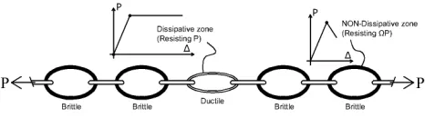
In order to have ductile behaviour of the brace frames, dissipative and non-dissipative zones are normally defined by the seismic codes. In this context, in order to avoid fragile failures and elastic instabilities in the structure other than the dissipative zones the components adjacent to the
dissipative members have to be designed in such a way so that they possess greater resistance than the dissipative members. This will ensure that they remain elastic and stable when overall deformations are taking place. This concept is known as “capacity design”.
Figure 1. Principle of capacity design by Paulay T. in 1992.
Priestley [1]. To highlight the concept of capacity design, the chain shown in Figure 1 is often considered [1, 2]. The strength of which is attributed to the weakest link, one ductile link may be used to achieve ductility for the entire chain. The nominal tensile strength of the ductile link is subjected to uncertainties of material strength and strain hardening effects at high strains. The other links are presumed to be brittle, but their failure can be prevented if their strength is in excess of the real strength of the ductile weak link at the level of ductility envisaged.
2. Concentric Cross Braced Frames
(CCDFs)
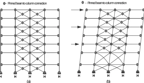
Figure 2. Concentrically Braced Frames: (a) general scheme; (b) collapse
Mechanism.
Cross (X) diagonal bracing as shown in Figure2, for example, usually are very slender and has large tensile capacity and possesses very low compressive buckling capacity. Such braces may be an economical design solution for lateral loads but permits concentration of inelastic deformations. Furthermore, compare to moment resisting frames, the energy dissipation during major earthquakes is low. As a result, X bracing is restricted to be employed in less seismically active zones or very short structures in more active zones[3, 4]. It has generally been believed within the structural engineering community that the seismic performance of concentric braced frames is inferior to that of moment resisting frames and therefore, extensive damage has been observed in CBFs following many recent earthquakes, such as the 1985 Mexico, 1989 Loma Prieta, 1994 Northridge, and 1995 Hyogo-ken Nanbu events [5, 6]. Because of such damages, building codes stipulate comparatively low values for the response modification factor used in design to account for the inherent ductility of the XCBF systems. Furthermore restrictions are imposed for braced frames located in regions of high seismic risk. However, with the introduction of more complex and stringent guidelines when using capacity design approach for the design and construction of ductile welded moment resisting frames following the Northridge earthquake, a rapid increase in the use of special concentrically braced frames has occurred, especially for low- and mid-rise construction. In general, the energy dissipation of concentric
braced frames is strongly influenced by post buckling brace behaviour. This is quite different for slender braces than for stocky braces. For example, the compressive strength of a slender brace is much smaller in later cycles of loading than it is in the first cycle. Additionally, compare to stocky braces, very slender braces offer less energy dissipation but are able to sustain more loading cycles and larger inelastic deformation.
Generally, the reduction in compressive capacity is applied because of the loss of compressive resistance expected during cyclic loading after the initial buckling cycles. However, the reduction is not used in the evaluation of the maximum forces that can be transferred to adjacent members. Bracing, contributing most of the lateral strength and stiffness to frames, resists most of the seismic load. From economy point of view it is quite attractive to design bracing as tension members only, since steel is very efficient in tension. However, this result in poor inelastic behaviour under severe earthquake loading and is a major reason for excluding X bracing from seismically active regions. On the other hand, more energy is dissipated in a brace yielding in tension than in a brace buckling in compression. As a result, all bracing systems must be designed so that at least 30%, but no more than 70%, of the base shear is carried by bracing acting in tension, while the balance is carried by bracing acting in compression [7, 8].
The overall and local slenderness of bracing is important which can be achieved by width to thickness ratio of the brace member. Beyond the restrictions of width to thickness, the bracing may be compact or non-compact, but they must not exceed the limit for slender members as reported in the AISC-LRFD [7] provisions instead in EC8 non-dimensional Slenderness λ needs to be fulfilled.
The energy dissipation in the connections must not be encouraged; therefore the strength of the connections should be stronger than the members themselves. For ordinary concentrically braced frames, this is achieved by first assuring that the connections are capable of developing the brace forces produced by the load combinations with the overstrength factor of 2.0. In addition, the connections must be designed to resist the maximum tensile strength of the brace considering the full uncertainty of the yield stress in the brace members[9].
3. Synoptic Table for CCBFs
Comparison of the capacity design rules according to Eurocodes [10, 11] versus AISC-ASCE [8, 12] for the design of CBF, the noticeable features provided by the relevant codes are illustrated briefly in the synoptic comparative scheme given in Table 1 [13].
According to Table 1, DCL is Ductility Class Low, DCM is Ductility Class Medium and DCH is Ductility Class High; SCBF is Special Concentric Braced Frame, OCBF is Ordinary Concentric Braced Frame. These abbreviations are henceforth used in the current paper.
(a) (b)
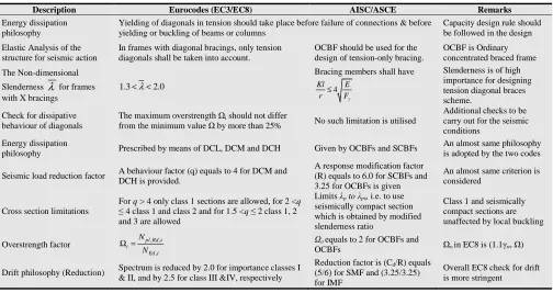
Table 1. Seismic Provisions for Concentric Cross Braced Frames.
Description Eurocodes (EC3/EC8) AISC/ASCE Remarks
Energy dissipation philosophy
Yielding of diagonals in tension should take place before failure of connections & before yielding or buckling of beams or columns
Capacity design rule should be followed in the design
Elastic Analysis of the structure for seismic action
In frames with diagonal bracings, only tension diagonals shall be taken into account.
OCBF should be used for the design of tension-only bracing.
OCBF is Ordinary concentrated braced frame The Non-dimensional
Slenderness λ for frames with X bracings
1.3< <λ 2.0
Bracing members shall have
4 y Kl E r ≤ F
Slenderness is of high importance for designing tension diagonal braces scheme.
Check for dissipative behaviour of diagonals
The maximum overstrength Ωi should not differ
from the minimum value Ω by more than 25% No such limitation is utilised
Additional checks to be carry out for the seismic conditions
Energy dissipation
philosophy Prescribed by means of DCL, DCM and DCH Given by OCBFs and SCBFs
An almost same philosophy is adopted by the two codes
Seismic load reduction factor A behaviour factor (q) equals to 4 for DCM and DCH is provided.
A response modification factor (R) equals to 6.0 for SCBFs and 3.25 for OCBFs is given
An almost same criterion is considered
Cross section limitations
For q > 4 only class 1 sections are allowed, for 2 <q ≤ 4 class 1 and class 2 and for 1.5 <q ≤ 2 class 1, 2 and 3 are allowed
Limits λp to λps, i.e. to use
seismically compact section which is obtained by modified slenderness ratio
Class 1 and seismically compact sections are unaffected by local buckling
Overstrength factor , ,
, pl Rd i i
Ed i N
N
Ω = Ωo equals to 2 for OCBFs and
OCBFs Ωo in EC8 is (1.1γovΩ) Drift philosophy (Reduction) Spectrum is reduced by 2.0 for importance classes I
& II, and by 2.5 for class III &IV, respectively
Reduction factor is (Cd/R) equals
(5/6) for SMF and (3.25/3.25) for IMF
Overall EC8 check for drift is more stringent
4. Eurocode 8 Provisions for CCBFs
Like other lateral load resisting systems, the seismic design approach proposed in the Eurocode 8 [14], for concentric braced frames (CBFs) aimed to achieve a ductile and dissipative ultimate behaviour. This can be obtained by imposing capacity design approach in which yielding of diagonal members take place prior to the failure of beams, columns and connections [15].In order to obtain such strength hierarchy among the structural member, EC8 provides a simplified design procedure, which requires a linear analysis of the CBF structure under reduced seismic loads. Furthermore, with reference to CCBF, the simplified procedure involves the following:
Figure 3. Axial forces in diagonal and column: (a) Tension only model
and (b) Tension compression model.
• the reduction of the elastic design spectrum through a behaviour factor (q) equals to 4 for both DCM and DCH;
• For the evaluation of the design axial forces in the braced frame members (Figure 3) the tension-only diagonals scheme is used;
• a maximum allowable value for the non-dimensional slenderness
λ
of diagonals given in Eq (1) needs tobe fulfilled
0 . 2 ≤
λ (1)
This limitation of
λ
is used to ensure satisfactory behaviour under cyclic loading and is defined as the square root of the ratio between the plastic resistance Npl, Rd and the Eulerian buckling load Ncr of the diagonal as shown by Eq (2)., pl Rd
cr
N N
λ = (2)
• a minimum allowable value for the non-dimensional slenderness
λ
of diagonals given by Eq (3) needs tobe respected.
3
1.
>
λ
(3)This limitation is for the case of cross bracing configurations (X-CBFs), devoted to avoid overloading of columns in the pre-buckling stage of compressed diagonal, i.e. when the actual structural scheme is the Tension/Compression one of Figure 3b;
α
F
(a)
N
Pl,Rdd
F
ξ
N
Pl,Rd d dα
(b)
α
F
N
Pl,Rd dN
Ed,E cF
α
N
Ed,E c• the definition of a system overstrength factor Ω
defined as the minimum value among the diagonal overstrength coefficient Ωi of the same braced frame (Eq 4), i.e.:
( )
min i
Ω = Ω (4)
where, Ωi is the diagonal overstrength coefficient for the
i-th diagonal members of i-the considered braced frame,
defined as the axial strength capacity to demand ratio, given by Eq (5).
, , , pl Rd i i
Ed i
N N
Ω =
(5)
maximum allowable value for the difference between the maximum (Ωmax) and the minimum (Ωmin) values of the diagonal overstrength coefficients Ωi, according to Eq (6).
max min
1.25
Ω ≤
Ω (6)
devoted to obtain a uniform distribution of plastic demand along the building height, thus reducing the potential for damage concentration and eventual soft-storey mechanisms; • the amplification of design axial forces in beam and
columns (non-dissipative elements) through the system overstrength factor Ω, using Eq (7).
, ,
1.1
,pl Rd col Ed G ov Ed E
N
−≥
N
+
⋅
γ
⋅Ω ⋅
N
(7)where: Npl,Rd-col is the required axial strength capacity for
the generic column/beam, NEd,E is the design axial force in
the generic column/beam due to seismic actions; NEd,G is
the design axial force in the generic column/beam at the storey i due to the non-seismic actions included in the seismic load combination; γov is the material overstrength
factor.
5. Eccentric Braced Frames (EBFs)
There are a number of special design provisions that must be satisfied by Eccentric Braced Frames. In EBF, link must be provided at least at one end of each brace. The link beam should be designed so that it is the weak part (dissipative zone) of the structure under severe seismic loading which is achieved by selecting the size of the steel section and the length of the link beam to match seismic-load design requirements. Yielding or buckling of the columns must also be avoided. The brace and column
design forces are needed to ensure that the brace and column do not buckle as the link beam strain hardens during inelastic deformation.
Eccentrically braced frames as shown in Figure 4 are a sort of “compromise” between moment resisting frames and concentrically braced frames as combine the strength and stiffness of a concentric braced frame with the inelastic performance of a special moment-resisting frame. Also in terms of architectural flexibility, the EBF solution shows intermediate peculiarities. Therefore, the most attractive feature of EBFs for seismic-resistant design is their high stiffness combined with excellent ductility and energy-dissipation capacity. The braces in EBFs deliver the high elastic stiffness characteristic of CBFs, permitting code drift requirements to be met economically and in addition, under severe earthquake excitation, properly designed and detailed EBFs provide the ductility and energy dissipation capacity characteristic of MRFs [16].
At the same time, since at least one end of the braces is connected to the beams, a part of these, usually called “link”, is devoted to the dissipation of the input energy, by yielding in shear and/or in flexure.
In this way, the stiffness and ductility properties can be in principle adequately calibrated, so leading towards optimal structural solutions. The performances of the structure are strongly dependent on the behaviour of the links, which require particular care in the phase of design [3].
Figure 4. Eccentrically braced frames: general scheme (a) and collapse
mechanism (b).
6. Synoptic Table for EBFs
In the following synoptic scheme Comparison of the capacity design rules according to Eurocodes [10, 11] versus AISC-ASCE [8, 12] for the design of EBF, the noticeable features provided by the relevant codes are illustrated briefly given in Table 2 [13].
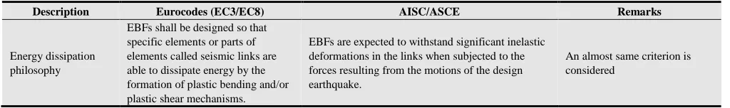
Table 2. Provisions for Eccentric Braced Frames.
Description Eurocodes (EC3/EC8) AISC/ASCE Remarks
Energy dissipation philosophy
EBFs shall be designed so that specific elements or parts of elements called seismic links are able to dissipate energy by the formation of plastic bending and/or plastic shear mechanisms.
EBFs are expected to withstand significant inelastic deformations in the links when subjected to the forces resulting from the motions of the design earthquake.
An almost same criterion is considered
(a) (b)
Description Eurocodes (EC3/EC8) AISC/ASCE Remarks Rotation capacity
(local ductility concept)
Plastic hinge rotation is limited to 35 mrad for structures of DCH and 25 mrad for structures of DCM
Link rotation angle shall not exceed (a) 0.08 radians for links of length 1.6Mp/Vp or less and (b) 0.02
radians for links of length 2.6Mp/Vp or greater.
For high seismicity it is recommended by both codes to apply ductility concept
Dissipative members
Plastic Hinges should take place in links prior to yielding or failure elsewhere.
EBFs are expected to withstand significant in-elastic deformations in the links when subjected to forces resulting from the motions of the design earthquake.
Links can be short, long and Intermediate. Which fail due to Shear, bending and bending & Shear respectively.
Design Checks
If NED / Npl,Rd≤0.15 then Check for
Design Resistance of Link is VED ≤Vp,link
MED ≤Mp,link
Effect of axial force on the link, available shear strength need not be considered if Pu≤ 0.15Py
(LRFD) or Pa≤ 0.15/1.5Py (ASD)
NED, MED& VED respectively are
the design axial force, design bending moment and design shear at both ends of the link.
Check to achieve global dissipative behaviour of the structure
The maximum overstrength Ωi should not differ from the minimum value Ω by more than 25%
Ω is a multiplicative factor which is the minimum value of Ωi=1.5V p,link,i/VED,I among all short links and minimum value of
Ωi=1.5Mp,link,i/MED,I among all intermediate and long links.
Cross section limitations
For q > 4 only class 1 sections are allowed, for 2 < q ≤ 4 class 1 and class 2 and for 1.5 < q ≤ 2 class 1, 2 and 3 are allowed
Limits λp to λps, i.e. to use seismically compact
section and is obtained by modified slenderness ratio
Class 1 and seismically compact sections are unaffected by local buckling
Seismic load reduction factor
A behaviour factor (q) equal to 4 for DCM and5αu/α1 for DCH is
provided.
A response modification factor (R) equal to 8.0 for EBFs is given
An almost same criterion is considered
Overstrength factor
the minimum value of Ωi = 1,5
Vp,link,i /VEd,i among all short links,
whereas the minimum value of Ωi =
1,5 Mp,link,i/MEd,i among all
intermediate and long links;
Ωo equal to 2 for EBFs is given Ωo in EC8 is (1.1γovΩ)
Drift philosophy (Reduction)
Spectrum is reduced by 2.0 and 2.5 for importance classes I & II, and III &IV, respectively
Reduction factor is (Cd/R) equals (4/8) for EBF
Overall EC8 check for drift is more stringent
VEd,i, MEd,i are the design values of the shear force and of the bending moment in Link i in the seismic design situation;
Vp,link,i, Mp,link,i are the shear and bending plastic design resistances of link i
7. Eurocode 8 Provisions for EBFs
Eurocode 8 gives simple rules for the designing of EBFs where the seismic energy dissipation is taken by vertical or horizontal seismic links. According to the behaviour of link due to their dimensions and internal forces, three different types of links are defined by the code, namely, the short link (dissipation is guaranteed by yielding in shear), the long link (link dissipate energy by yielding in flexure) and the intermediate link (where plastic mechanisms is due to bending and shear).Links are design to satisfy the criteria given in Eq (8).
(
)
(
)
, ,
,
,
and being
and 3
Ed p link Ed p link
y p link w f
p link y f f
V V M M
f
V t d t
M f bt d t
≤ ≤
= −
= −
(8)
The plastic mechanism achieved in seismic links depends on their length e. Short links yield essentially in shear, and the energy dissipated in the plastic mechanism is given by Eq (9):
, v p link p
W
=
V
×
θ
×
e
(9)If a link is subjected to asymmetrical action effect M, the
energy dissipation is given by Eq (10).
,
2
M p link p
W
=
M
×
θ
(10)The limit between long and short links corresponds to the situation in which yielding could equally take place in shear or bending, therefore Eq (11) explains the case.
, ,
,
,
2
2
v M p link p p link p
p link
p link
W W V e M
M e
V
θ θ
= ⇒ × × = ×
⇒ = ×
(11)
Figure 5. Energy (W) dissipation a) for plastic shear mechanism and b)
for plastic bending mechanism.
, , 1.6 p link s
p link
M
e e
V
< = ×
(12)
The value of e for considering only a plastic mechanism in bending (long links) is calculated using Eq (13).
,
,
3 p link
L
p link M e e
V
< = ×
(13)
Between these two values es and eL, links are said to be
‘intermediate’ and the interaction between shear and bending has to be considered. If the typology of the structure is such that the shear and bending moment diagrams are not symmetrical, only one plastic hinge will form if the link is long, therefore Eq (14) takes place.
,
M p link p
W =M ×θ (14)
In this case, the limiting length between long and short links corresponds to Eq (15).
,
,
p link
p link M e
V
⇒ =
(15)
,
0.15
Ed Pl Rd
N
N ≤ (16)
If Eq (16) is satisfied the following conditions must be satisfied.
, and ,
Ed p link Ed p link V ≤V M ≤M
In cases, when Eq (17) is satisfied.
,
0.15? Ed
Pl Rd
N
N > (17)
Then plastic shear and moment should be reduced by the effect of axial forces in the bracings.
The recommended inelastic rotation limits for different link lengths without restriction on the configuration of the link are; 0.08 radians or 4.60for Short links, 0.02 radians or 1.150 for Long links, whereas for Intermediate links the value is determined by linear interpolation. The criterion is similar for both EBF and CBF and must be satisfied in order to form a global plastic mechanism. Furthermore, for a homogenise dissipation of energy, the overstrength Ωi
along the height of the building (for short and long links) is calculated using Eq (18) and Eq (19), respectively:
Short links: , ,
, 1.5 pl Rd i i
Ed i
V V
Ω =
(18)
Long links: , ,
, 1.5 pl Rd i i
Ed i
M M
Ω =
(19)
The minimum value of Ωi should be used in the design,
further the maximum value of Ωi should not differ from the minimum by more than 25%. Ωi is the minimum value of
Ωi that will ensure that yielding occurs simultaneously at several places over the height of the building, and a global mechanism is formed. The beams, columns and connections are ‘capacity designed’ relative to the real strengths of the seismic links. This is achieved by satisfying Eq (20):
, ,
, ,
1.1 Ω
and for connections ( , )
1.1 Ω
Rd Ed Ed Ed G Ov Ed E
d d G Ov i d E
N M V N N
E E E
γ
γ
≥ +
≥ +
(20)
8. Conclusions
The paper addressed the design procedure of Cross Concentric Braced Frames and Eccentric Braced Frames according to Eurocode 8 provisions. In addition synoptic tables are given for the two brace systems where the comparisons of the Eurocode 8 with AISC seismic provisions are presented, which follow the capacity design approach. From the tables it is evident that the design provisions of AISC are straight forward, e.g. in the case of overstrength factor a value of 2.0 is suggested by AISC code instead a more realistic approach is given in the case of Eurocode 8. The overstrength in Eurocode 8 for CCBF is given as the ratio of the axial plastic resistance of the brace to the axial design action. Moreover, the slenderness limitations, as well as the minimum overstrength requirement need to be fulfilled. In the case of EBF, the overstrength factor in EC8 is given by the ratio of the plastic shear resistance to the applied design shear action when the link is short or the ratio of the plastic flexural resistance to the applied design flexural action when the link is long. With regard to the reduction of seismic action (behaviour factor in EC8 and Response modification factor in AISC) quite high factor is given by the AISC for EBF (R equals 8) compare to EC8 (q equals 5αu/ α1 for DCH and 4.0 for DCM). In general it is concluded that the seismic provisions of EC8 seem complicated compare to that of AISC with clear differences in the proposed values of the important factors that are normally adopted by the seismic codes. These necessitate a more detail study of the two codes in future studies by presenting some case studies incorporating the design procedures of the two modern seismic codes. This will allow presenting a clear picture of the two codes.
References
[1] T. Paulay and M. J. N. Priestley, Seismic design of reinforced
concrete and masonry buildings: Wiley Online Library, 1992.
[2] A. Plumier, "General report on local ductility," Journal of
Constructional Steel Research, vol. 55, pp. 91-107, 2000.
[4] M. T. Naqash, "Optimum design of Steel Moment Resisting Frames using Eurocode 8," PhD Doctorate Thesis, Department of Engineering and Geology, University of Chiete and Pescara, Pescara, 2012.
[5] R. Sabelli, et al., "Seismic demands on steel braced frame buildings with buckling-restrained braces," Engineering
Structures, vol. 25, pp. 655-666, 2003.
[6] P. Uriz and S. A. Mahin, "Seismic performance assessment of concentrically braced steel frames," in Proceedings of the
13th world conference on earthquake engineering, 2004, p. 6.
[7] ANSI/AISC-360-10, "Specification for structural steel
buildings," ed. Chicago, Illinois 60601-1802: American
Institute of Steel Construction, 2010.
[8] ANSI/AISC-341-10, "Seismic provisions for structural steel
buildings," ed. Chicago, Illinois 60601-1802: American
Institute of Steel Construction, 2010.
[9] A. Elghazouli, "Assessment of capacity design approaches for steel framed structures," Journal of Steel Structures, vol. 5, pp. 465-475, 2005.
[10] EN-1993-1-1, "Eurocode 3. Design of steel structures, Part
1-1: General rules and rules for buildings," in European Committee for Standardization, CEN, ed. 36 B-1050,
Brussels, 2005.
[11] EN-1998-1, "Eurocode 8, Design of Structures for
Earthquake Resistance, Part 1: General rules, seismic actions and rules for buildings," in European Committee for Standardization, CEN, ed. 36 B-1050, Brussels, 2005.
[12] ASCE/SEI-7-10, "Minimum design loads for buildings and other structures," ed. 1801 Alexander Bell Drive Reston, Virginia 20191: American Society of Civil Engineers, 2010. [13] M. T. Naqash, et al., "Seismic design of Steel Moment
Resisting frames-European Versus American Practice," NED
University Journal of Research, vol. THEMATIC ISSUE
ON EARTHQUAKE, 2012, In Press In Press.
[14] EN-1998-1, "Eurocode 8, Design of Structures for Earthquake Resistance, Part 1: General rules, seismic actions and rules for buildings," in European Committee for
Standardization, CEN, ed. 36 B-1050, Brussels, 2005.
[15] O. Bursi and J.-P. Jaspart, "Calibration of a finite element model for isolated bolted end-plate steel connections,"
Journal of Constructional Steel Research, vol. 44, pp.
225-262, 1997.
[16] C. W. Roeder and E. P. Popov, "Inelastic behavior of eccentrically braced steel frames under cyclic loadings,"
NASA STI/Recon Technical Report N, vol. 78, p. 20375,