http://www.sciencepublishinggroup.com/j/ns doi: 10.11648/j.ns.20170203.12
An Analysis of GTRFW Initiation Using Finite Element
Method
William Richard Campbell
*, Jerry Chen
Engineering Research Institute, Auckland University of Technology, Auckland, New Zealand
Email address:
[email protected] (W. R. Campbell) *
Corresponding author
To cite this article:
William Richard Campbell, Jerry Chen. An Analysis of GTRFW Initiation Using Finite Element Method. Nuclear Science. Vol. 2, No. 3, 2017 pp. 82-86. doi: 10.11648/j.ns.20170203.12
Received: June 18, 2017 Accepted: July 3, 2017 Published: August 1, 2017
Abstract:
Understanding the Grid to rod fretting wear (GTRFW) initiation is critical for reducing the risk of fuel leak. In this paper, a simplified 3D FEA model is set up to analyze its mechanics. The initiation of GTRFW under a series of interferences was modeled and analyzed. It is found that slip and wear usually initiate from the edge of the grid to rod contact contour and eventually propagates to the entire contour. Due to the stress concentration, the contact at sharp corners should be avoided.Keywords:
GTRFW, Wear, Slip, PWR1. Introduction
Fretting wear is a damage mechanism in many engineering applications [1-10]. GTRFW is a major cause of cladding failures in pressurized water reactors (PWR). GTRFW problems are caused by coolant-induced vibration and insufficient support [11]. In a PWR, the fuel rods are supported by preloaded spacer grids. Due to high temperature and irradiation, the preload force is relaxed. When the support becomes insufficient, the turbulent force due to the coolant causes vibrations. The relative motion between the contact surfaces of cladding and rod, i.e. grid to rod fretting, will then cause wear. Eventually, the fretting wear may cause fuel leak, which is a threat to the safety [11-14]. Therefore, an investigation of the initial creep process is crucial for understanding the initiation of fretting wear.
Both experimental and numeric analyses have been done to study the GTRFW problems. Kim et al. developed a testing rig to study the key factors of GTRFW problems. They found the transportation, fuel rod loading, coolant flow and grid to rod gap are critical factors [11, 15-21]. Through numeric simulations, Rubiolo et al. statistically characterized the force due to the coolant flow. They developed a 1 D model which allows modeling of factors such as excitation force and grid to rod gap on vibrations and wear. Hu et al. developed a novel wear modeling
technique allowing efficient simulation of the GTRFW in 3D FEA models [22-26]. Through a systematic modeling of the gap sizes and excitation frequencies, they found the maximum wear rate is determined by a system resonance frequency, which is the root cause of the GTRFW [27]. The risk of GTRFW can be significantly reduced by avoiding the resonance frequency. Significant progress has also been made by Pu et al. in understanding the microscopic properties of materials in the reactor through innovative experiments and theoretical studies [28-33]. Efforts have also been made by Kim et al. to study the contact mechanics on the grid to rod interface [34-38]. It was found a concave spring contour would reduce the wear rate. In this paper, the initiation of GTRFW is modeled using a simplified 3D FEA model. Since the preload is closely related to the interference, a series of interferences are used to study their effects on the slip and wear.
2. Methodology
significant, which causes stress relaxation. The involvement of those factors would significantly increase the complexity in modeling the contact interface [39-42]. The turbulence of the coolant flow causes vibration. When the contact stress is relaxed by creep and wear, the vibration will eventually overcome the support force and cause fretting wear [11, 12]. Therefore, it is necessary to study the stress relaxation caused by creep and predict the critical scenario at which the fretting will occur.
To simulate this process, a simplified 3 D finite element model is built in the FEA code ABAQUS. The key dimensions is set up according to the real values as shown in Table 1 [37]. So there will be a preload on the contact interface between the grid and fuel rod. A Coulomb’s friction law will be used to model the maximum static and friction stress, and the equation is as follows,
= c
f σ µ (1)
where f is the critical friction stress when slip occurs,
σ
cis the contact pressure andµ
is the friction coefficient. That means if the contact shear stress of at a node of the contactinterface is equal to the friction stress, slip will occur there. When creep strain grows, the contact pressure at the interface will decrease, so the critical friction stress will decrease as well. When the contact shear stress is large enough to overcome the friction, slip will occur. Because the contact pressure and contact shear stress may be different from one location to another, the partial slip will occurs locally at the beginning and eventually becomes full slip. In this study, instead of modeling the creep evolution, a series of different interferences are used. Those interferences would provide different preload that represents different stages of stress relaxation.
Table 1. Key parameters of the FEA model.
Cladding thickness 0.57 mm
Cladding diameter 9.5 mm
Rod length (2 spans) 150 mm
Density of Zircaloy 4 6.5×10⁻³ g/ mm³
Young’s modulus of Zircaloy 4 75 GPa Poisson’s ratio of Zircaloy 4 0.37
Figure 1. A simplified with a fuel rod supported by a simplified spacer grid.
The FEM model is set up as shown in Figure 1. The assembly is composed by Zircaloy support springs and Zircaloy cladding. The detailed dimensions and material properties are listed in Table 1. The interference will be set up between the contact components through applying an initial displacement to the springs. Different interferences can be set up between the springs and the cladding in order to investigate their effect on the GTRFW. To simplify the study and eliminate the complexity of turbulent force, an axial displacement Da is used as the resultant coolant load.
3. Results
The contact pressure on the interface plays a key role in the GTRFW problems. When the local contact pressure is low, the support is not sufficient and the slip would occur once the fuel rod is subjected to a tangential load. When the
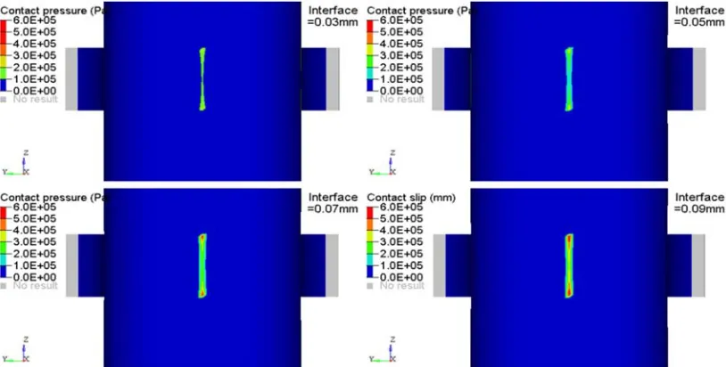
local contact pressure is high, a small amount of slip would lead to high work rate, leading to quick wear growth. Figure 2 shows the contact pressure under different interferences. The initial contact contour is relatively small, particularily when the interference is small. Due to the growth of creep and wear, this contour is expected to grow over time. The contact pressure near the edge of the contact is significantly higher than the interior area. This is due to the stress concentration at the contact edge. The spacer grid is manufactured from stamping sheet metals, which creates sharp corners of the springs. These high contact pressure would cause high wear rate.
the contact interface. As the interference increase, partial slip is observed. That is quite reasonable. Under a small interference, the preload is small too, leading to a relatively small static friction force. So the tangential load would easily
overcome the static friction force and cause gross slip. As the interference increases, the tangential load becomes insufficient to cause slip everywhere, and the partial slip occurs at the contact edge.
Figure 2. Initial contact pressure on the grid to rod interface under different interferences. The initial contact contour is relatively small and stress concentration is noticed at the contact edge.
Figure 3. Slip distance under different interference. Partial slip is noticed under large interference and full slip is noticed under small interference.
Figure 4 shows the pulling force needed to cause gross slip on the contact interface under a friction coefficient of 0.1. The force is basically linearly dependent on interference as the model is in elastic domain. For a given interference, if the pulling force is less than the critical value, the contact interference would have partial slip or full stick condition. The partial slip wear on the grid to rod interface has been observed both numerically by Hu et al [22-24, 43, 44] and experimentally by Kim et al [34, 35, 37]. Significant efforts have been made by Hu et al. to understand the initiation and propagation of partial slip wear. They found that the wear usually initiates from the contact edge and eventually propagates to the entire interface. Those findings well
explains the root mechanism of the GTRFW initiation.
4. Conclusions
Understanding the mechanism of GTFW is critical for predicting the fuel leak risk and optimizing the design of next generation PWR plants. In this study, a 3 D FEA model has been set up to analyze the initiation of GTFW. It is observed that the stress level around the edge of grid to rod interface is usually higher due to the stress concentration and the partial wear usually initiates from there. That would lead to a higher wear rate and the contact at those edges should be avoided. This observation is consistent with experimental observations and theoretical studies.
References
[1] Wei, C., J. Chan, and D. Garmire. 3-axes MEMS Hall-effect sensor. in Sensors Applications Symposium (SAS), 2011 IEEE. 2011.
[2] Ma, X., et al., Temperature effect on low-cycle fatigue behavior of nickel-based single crystalline superalloy. Acta Mechanica Solida Sinica, 2008. 21 (4): p. 289-297.
[3] Ma, X. and H.-J. Shi, On the fatigue small crack behaviors of directionally solidified superalloy DZ 4 by in situ SEM observations. International Journal of Fatigue, 2012. 35 (1): p. 91-98.
[4] He, J. and Y. Fuh-Gwo, A quantitative damage imaging technique based on enhanced CCRTM for composite plates using 2 D scan. Smart Materials and Structures, 2016. 25 (10): p. 105022.
[5] He, J. and F.-G. Yuan, Lamb-wave-based two-dimensional areal scan damage imaging using reverse-time migration with a normalized zero-lag cross-correlation imaging condition. Structural Health Monitoring, 2016: p. 1475921716674373. [6] He, J. and F.-G. Yuan, Lamb wave-based subwavelength
damage imaging using the DORT-MUSIC technique in metallic plates. Structural Health Monitoring, 2016. 15 (1): p. 65-80. [7] He, J. and F.-G. Yuan, Damage identification for composite
structures using a cross-correlation reverse-time migration technique. Structural Health Monitoring, 2015. 14 (6): p. 558-570.
[8] Wei, C. and L. L. Gouveia, Modeling and simulation of Maximum power point tracker in Ptolemy. Journal of Clean Energy Technologies, 2013. 1 (1): p. 6-9.
[9] Wei, C. and F. Shi, High Performance SOI RF Switch for Healthcare Application. International Journal of Enhanced Research in Science, Technology & Engineering, 2016. 5 (10): p. 23-28.
[10] Wei, C., J. Xu, and S. Wang, Low Power SI Class E Power Amplifier for Healthcare Application. International Journal of Electronics Communication and Computer Engineering, 2016. 7 (6): p. 290-293.
[11] Kim, K.-T., The effect of fuel rod supporting conditions on fuel rod vibration characteristics and grid-to-rod fretting wear. Nuclear Engineering and Design, 2010. 240 (6): p. 1386-1391. [12] Feng, B., A. Karahan, and M. S. Kazimi, Steady-state fuel behavior modeling of nitride fuels in FRAPCON-EP. Journal
of Nuclear Materials, 2012. 427 (1–3): p. 30-38.
[13] Wang, Z.-X., et al., Small punch testing for assessing the fracture properties of the reactor vessel steel with different thicknesses. Nuclear Engineering and Design, 2008. 238 (12): p. 3186-3193.
[14] Ma, X., et al., In-situ observations of the effects of orientation and carbide on low cycle fatigue crack propagation in a single crystal superalloy. Procedia Engineering, 2010. 2 (1): p. 2287-2295.
[15] Kim, K. and J. Suh, Impact of nuclear fuel assembly design on grid-to-rod fretting wear. Journal of Nuclear Science and Technology, 2009. 46: p. 149–157.
[16] Kim, K.-T., The study on grid-to-rod fretting wear models for PWR fuel. Nuclear Engineering and Design, 2009. 239 (12): p. 2820-2824.
[17] Kim, K.-T., The effect of fuel rod loading speed on spacer grid spring force. Nuclear Engineering and Design, 2010. 240 (10): p. 2884-2889.
[18] Kim, K.-T., A study on the grid-to-rod fretting wear-induced fuel failure observed in the 16×16 KOFA fuel. Nuclear Engineering and Design, 2010. 240 (4): p. 756-762.
[19] Kim, K.-T., Applicability of out-of-pile fretting wear tests to in-reactor fretting wear-induced failure time prediction. Journal of Nuclear Materials, 2013. 433 (1–3): p. 364-371. [20] Kim, K.-T. and J.-M. Suh, Development of an advanced PWR
fuel for OPR 1000s in Korea. Nuclear Engineering and Design, 2008. 238 (10): p. 2606-2613.
[21] Kim, K.-T. and J.-M. Suh, Impact of nuclear fuel assembly design on Grid-to-Rod Fretting Wear. Journal of Nuclear Science and Technology, 2009. 46 (2): p. 149-157.
[22] Hu, Z., W. Lu, and M. D. Thouless, Slip and wear at a corner with Coulomb friction and an interfacial strength. Wear, 2015. 338–339: p. 242-251.
[23] Hu, Z., et al., Simulation of wear evolution using fictitious eigenstrains. Tribology International, 2015. 82, Part A (0): p. 191-194.
[24] Hu, Z., et al., Effect of plastic deformation on the evolution of wear and local stress fields in fretting. International Journal of Solids and Structures, 2016. 82: p. 1-8.
[25] Wang, H., et al., A mechanism-based framework for the numerical analysis of creep in zircaloy-4. Journal of Nuclear Materials, 2013. 433 (1–3): p. 188-198.
[26] Lu, W., et al., CASL Structural Mechanics Modeling of Grid-to-Rod Fretting (GTRF). JOM, 2016. 68 (11): p. 2922-2929. [27] Hu, Z., M. D. Thouless, and W. Lu, Effects of gap size and
excitation frequency on the vibrational behavior and wear rate of fuel rods. Nuclear Engineering and Design, 2016. 308: p. 261-268.
[28] Pu, C. and Y. Gao, Crystal Plasticity Analysis of Stress Partitioning Mechanisms and Their Microstructural Dependence in Advanced Steels. Journal of Applied Mechanics, 2015. 82 (3): p. 031003-031003-6.
[30] Pu, C., et al., Diffusion-coupled cohesive interface simulations of stress corrosion intergranular cracking in polycrystalline materials. Acta Materialia, 2017. 136: p. 21-31.
[31] Sham, S., et al., Report on FY15 alloy 617 code rules development. 2015: United States.
[32] Wang, Y., et al., Report on FY15 Alloy 617 SMT Creep-Fatigue Test Results. 2015; Oak Ridge National Laboratory (ORNL). p. Medium: ED; Size: 56 p.
[33] Wang, Y., et al., Report on FY15 Two-Bar Thermal Ratcheting Test Results. 2015; Oak Ridge National Lab. (ORNL), Oak Ridge, TN (United States). p. Medium: ED; Size: 39 p. [34] Kim, H.-K., Mechanical analysis of fuel fretting problem.
Nuclear Engineering and Design, 1999. 192 (1): p. 81-93. [35] Kim, H. K., D. A. Hills, and D. Nowell, Partial slip between
contacting cylinders under transverse and axial shear. International Journal of Mechanical Sciences, 2000. 42 (2): p. 199-212.
[36] Kim, H.-K., et al., Fretting wear of laterally supported tube. Wear, 2001. 250 (1–12): p. 535-543.
[37] Kim, H.-K., Y.-H. Lee, and S.-P. Heo, Mechanical and experimental investigation on nuclear fuel fretting. Tribology International, 2006. 39 (10): p. 1305-1319.
[38] Kim, H.-K., Y.-H. Lee, and K.-H. Lee, On the geometry of the fuel rod supports concerning a fretting wear failure. Nuclear Engineering and Design, 2008. 238 (12): p. 3321-3330. [39] Xu, Q., et al., Robust self-cleaning and micromanipulation
capabilities of gecko spatulae and their bio-mimics. 2015. 6: p. 8949.
[40] Xu, Q., et al., Three-dimensional micro/nanoscale architectures: fabrication and applications. Nanoscale, 2015. 7 (25): p. 10883-10895.
[41] Xu, Q., et al., Dynamic Adhesion Forces between Microparticles and Substrates in Water. Langmuir, 2014. 30 (37): p. 11103-11109.
[42] Xu, Q., et al., Dynamic Enhancement in Adhesion Forces of Microparticles on Substrates. Langmuir, 2013. 29 (45): p. 13743-13749.
[43] Wang, H., et al., The effect of coupled wear and creep during grid-to-rod fretting. Nuclear Engineering and Design, 2017. 318: p. 163-173.