A N ew C o m p u t a t i o n a l M o d e l
for
Op t i c al A n a l y s i s
A Thesis Subm itted for the Degree
of
D octor of Philosophy of the University of London
by
Ronald Szumski
Optical Science Laboratory
Department of Physics and Astronomy
University College
University of London
1998
ProQuest Number: U643664
All rights reserved
INFORMATION TO ALL USERS
The quality of this reproduction is dependent upon the quality of the copy submitted.
In the unlikely event that the author did not send a complete manuscript and there are missing pages, these will be noted. Also, if material had to be removed,
a note will indicate the deletion.
uest.
ProQuest U643664
Published by ProQuest LLC(2016). Copyright of the Dissertation is held by the Author.
All rights reserved.
This work is protected against unauthorized copying under Title 17, United States Code. Microform Edition © ProQuest LLC.
ProQuest LLC
789 East Eisenhower Parkway P.O. Box 1346
Abstract
Acknowledgements
I would like to take this opportunity to give recognition to those in my life who have been instrum ental in my completing this doctorate. My greatest thanks go to my wife, who gave me much emotional and practical support, allowing me to step out of the family circle when necessary and into th a t solitary existence th a t all researchers are all too familiar with. My son Gregory, who is now 9 years old, thankfully proved to be the necessary counterweight, often reminding me th a t the real world has even greater rewards. My m other too was very supportive and gave me encouragement through the years. U nfortunately my father died ju st a few months before I commenced this work, but it was he who many years ago first set me on the road to science. I wouldn’t have made it w ithout him. On a practical note, my farsighted employer allowed me to take the necessary time off to complete this w ritten work. Thankyou, M ats.
C o n t e n t s
1 In tro d u ctio n 12
1.1 E v o l u tio n ... 16
1.2 Handling C o m plexity ... 18
1.3 A New V iew po in t... 18
2 Lens M o d ellin g 20
2.1 R e q u ire m e n ts ...21
2.2 The Surface-Based M o d e l ...23
2.3 The Component-Based M o d e l...27
3 O b ject O rien ted P ro g ra m m in g 34
3.1 E n ca p su latio n ...36
3.2 I n h e r i t a n c e ...39
3.3 Polym orphism ...42
4 Im p lem en ta tio n D e ta ils 46
4.1 Com puter P la tfo rm ... 46
4.2.1 Ch—|- ...50
4.2.2 Visual B a s ic ...53
4.2.3 D elphi/O bject Pascal ... 57
4.2.4 O ther Development T o o l s ...61
4.2.5 Conclusion ...61
5 D escrip tio n o f M o d el 63 5.1 The T o o lb a r... 64
5.2 The System F o rm ...66
5.3 The Lens Container ... 69
5.4 M ethods and Properties of T L e n s ...72
5.5 Editor L i n k a g e ... 75
5.6 Support M o d u le s ... 78
6 L ens In tern als 84 6.1 G lasses... 85
6.2 S u r f a c e s ... 87
6.2.1 The A bstract Surface ... 87
6.2.2 The Plane S u r f a c e ... 90
6.2.3 The Conic S u r f a c e ... 95
7 O p tical R ay Im p lem en ta tio n 99 7.1 Paraxial R a y s ...100
7.3 Ray C o n ta in e r s ...106
7.4 The Component-Ray Interface ...107
8 D eta ile d C o m p o n en t D escrip tio n s 112 8.1 The S o u r c e ... 113
8.2 The S p a c e r ... 117
8.3 The Thick L e n s ...118
8.4 The R e fA lig n ... 121
8.5 The P r is m ... 124
8.6 The Double-Pass C o m p o n en ts...125
9 O p tical S y ste m P ro c esse s 129 9.1 Validating the S y s t e m ...132
9.2 The Lens Sequencing A lg orith m ...136
9.3 Pupil L o c a t i o n ...140
9.4 O ther System P r o c e s s e s ... 144
10 E valu ation o f M o d el 145 10.1 Raytracing Through Simple L e n s e s ... 148
10.2 Configuring the P r i s m ...151
10.3 Decollimating and Focussing of the O u tp ut B e a m ... 153
10.4 Raytracing a Littrow S p e c tro g ra p h ... 156
10.5 Conclusion ... 160
11.1 The O bject M o d e l ... 163
11.2 Improving the P i c t u r e ...164
11.3 Intelligence and O p tim is a tio n ...165
11.4 Classical O p tim is a tio n ...168
12 C o n clu sio n 171
L i s t o f F i g u r e s
2.1 The Doublet-Lens I c o n ...28
2.2 The Lens-System C o n ta in e r ... 29
5.1 The Toolbox ... 64
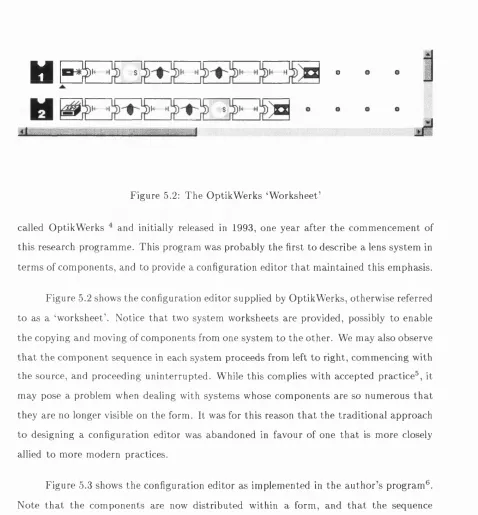
5.2 The OptikW erks ‘W orksheet’ ... 67
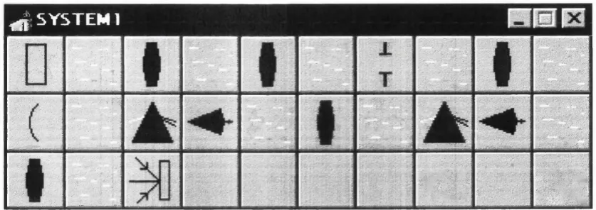
5.3 IRIS Configuration E d i t o r ...68
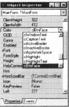
5.4 The Delphi O bject Inspector ...76
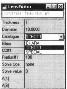
5.5 The IRIS Lens Editor In s p e c to r... 77
7.1 Paraxial Ray Types ...101
8.1 Source in Lens E d i t o r ... 114
8.2 Thick Lens in Lens E d i t o r ...119
8.3 The action of TRefAlign upon Reference Rays and R a y -S e ts ...121
8.4 A Simple S p ectro graph... 123
8.5 The Spectrograph F o r m ... 123
8.6 Prism in Lens E d i t o r ...125
9.1 Hierarchical structure of the IRIS p ro g ra m ... 130
9.2 The Source Pop-Up m e n u ... 132
9.3 An Example of Component In te rfa c in g ...134
10.1 The IRIS Program, showing analysis of Littrow M o u n t... 147
10.2 Arrangement of Components for Test ... 148
10.3 A rrangement of Components for Test ^ 2 ...152
10.4 A rrangement of Components for Test ^^3 ...154
10.5 The Zemax Program, showing analysis of Littrow M o u n t...157
10.6 The Littrow system as represented by I R I S ...159
Preface
When I first embarked upon this research program I had little idea where it would take me. Initially, the intention was to write a com puter program th a t would facilitate the analysis of complex optical systems, particularly systems such as astronomical spectrographs. One of the key features was to be the calculation of spectral thoughput, taking into consideration glass absorption and multi-layer inteference coatings.
One of the first problems th a t I encountered was the selection of a suitable com puter language in which to write the program. I had decided early on th a t the target operating system was to be Microsoft Windows v3.11, the most current version at the time. Suitable languages for this platform were C-1-+ and Turbo/B orland Pascal, and it was these th a t I explored in the initial stages. Shortly afterwards Visual Basic (VB) appeared. The writing of a Windows program was much facilitated by this new arrival, and it rapidly gained in popularity throughout the business world.
Eventually, it too began to show its limitations as my requirements slowly shifted with time. The lack of true O bject-Oriented Programm ing features meant th a t the rather complex ideas I was trying to develop could only be implemented with the greatest of effort. I had been aware some time earlier of a product known menacingly as VB Killer, or VBK. This was being developed by Borland International as a true object-oriented visual programming language. Its basis was a variant of Pascal known as O bject Pascal. I instinctively knew th a t this was to be my salvation, but would it arrive in time? I shall leave the
reader to ascertain the details further in this thesis.
regularly superseded by more advanced standards, more closely reflecting cur rent and future technologies.
If you think th a t the poor pedestrian would-be com puter user of today has a difficult time choosing which hardw are/softw are packages to invest in, then spare a thought for the programm er who is at the leading edge of his/her field. It is only through the actions of long-sighted companies, such as Microsoft and Borland, th a t the ever increasing complexity of the com puter world can be made manageable to lesser m ortals like ourselves. In doing so, such endeavours as these will allow those of us who seek to create new worlds the perfect and timely opportunity to do ju st th a t.
In a world where change is the norm, and complexity is the vehicle of change, I sometimes worry as to where it will all end. I think this because I cannot imagine a world where change, a t the pace we are used to today, can continue onwards indefinitely. Either science, the world’s resources or our own imagi nations, will eventually, I believe, falter. T h at said, the reader may conclude th a t I am one of the world’s many pessimists, and who am I to argue.
C h a p t e r 1
I n t r o d u c t i o n
The following chapters go into great detail as they begin to unfold for the reader each of the premises upon which this thesis is based, bu t it is probably appropriate a t this point if I try to summarise them in a m anner th a t is synonymous with a historical record, while also im parting the degree of inherent innovation th a t I believe each to have.
If a lens designer is unable to understand every syntactical nuance of d a ta entry, which results in incorrect d a ta being input into the program, then regardless of w hat power lies under the ‘hood’ {English: bonnet), it can never be properly realised. This dilemma caused me to reconsider the direction my work should take. I realised shortly afterwards th a t the real problem stemmed from the disparity in models th a t were held by the program and by the user. It became clear to me th a t during the many years th a t software was being developed for the purpose of enhancing the capabilities of the optical designer, at no time had any programmer ever considered the internal or imaginary model th a t a lens designer held, or so it appeared. It would be conceited indeed to think th a t users should, for a period of atleast 20 years, be required to abandon the physical model of a lens system in favour of a system based upon a sequentially ordered series of surfaces, but in fact this is exactly w hat has happened. Optical designers do not necessarily achieve a reputation based upon the quality of their designs or analyses alone, but also for their ability to understand the most complex workings of some of the most complex design programs. If the human-computer interface is so essential to the task of design and analysis, then why can’t it be made simpler? This was the question th a t I posed myself, and the solution I found is recorded herein.
filing cabinet icon, and its contents viewed as a list of documents.
The first challenge was the development of an ideological model around which I could create a system th a t supported the normal physical attrib utes and characteristics of a real optical system (i. e. lens insertion, deletion, copying, moving, editing, etc.) a t both the screen and code levels. Such a task in itself is quite a challenge, but fortunately there was one development tool (Delphi) th a t offered an environment th a t was object-oriented a t both these levels, and so completion of the task was atleast feasible. The main aim a t this stage was to arrive a t a form of development editor th a t minimised the use of the keyboard, and this was acheived by providing greater functionality for mouse operations. This approach proved to be quite successful, if measured by the fact th a t virtually all but one of the above functions (insertion, deletion, etc.) are completed through simple mouse operations.
The second challenge was to create a graphical screen environment th a t would pro vide the user with sufficient functionality to undertake the required operations as briefly outlined in the preceding paragraph. A m ajor step forward was the reduction of a gen eralised optical system into a much simpler form th a t conformed with normal design practices. The lens system as a whole was abstracted to resemble a standard window, while the lens elements were reduced to iconic form (components) th a t occupied distinct positions upon a rectilinear grid within the system window, much like a chess board pop ulated with chess pieces. System editing functions, such as lens moving and copying, are facilitated by the com puter mouse, much in the same way as these functions are accessed in Windows 3.X and other GUI operating systems. In axddition, non-optical components such as axial tilts and décentrations may be represented in a similar manner; in fact, using this architecture it is possible to represent and correctly integrate almost any optical and non-optical component into the system environment. This powerful feature is used later on (see C hapter 8) to develop the notion of a multi-pass optical component, something th a t is extremely difficult, or even impossible to simulate in current commercial software offerings.
Development (RAD) tools: component based programming environments such as Delphi and Visual Basic. The component editor has proved to be universally popular and ex tremely flexible, easily adapting to unforseen components of the future. I could do a lot worse than follow in the same footsteps as these giants of the software industry!
In order to bring all these ideas together into a working model it proved necessary to design many subsidiary software modules, not least the components themselves, which comprised such familiar elements as the prism and the single lens. Two such items th a t are not usually associated with an optical analysis program a t this stage of development are customised V ecto r and M atrix units. I had anticipated earlier on th a t since the tracing of polarised light rays might be an im portant feature of the program, then such modules would be of great benefit. In fact they are employed by virtually all algorithms th a t can possibly use them, with the exception of the routines responsible for ray transfer and ray refraction, which are coded for speed rather than elegance. Additionally, reflecting the versatility of the v e c to r class, the all-im portant finite ray is actually a vector ‘mas querading’ as a ray. Both the V ecto r and M atrix units supply the class definitions th a t enable real entities of either type to be created at any point within the code. In order to support the many operations th a t such types are capable of entering into, both units also provide class methods (procedures) th a t enable a large variety of fimiliar operators (dot, cross, vector rotation, etc.). A particular problem th a t I encountered involved those class m ethods th a t ideally should return a new object, but which proved difficult in practice due to the dynamic nature of the v e c to r and m a trix entities (see §5.6 for a more complete description of the problem and its solution). The solution proved to be both effective and innovative, and is known to be applicable to other categories of this problem peculiar to O bject Pascal and similar languages.
first step toward, for example, a self-optimising system - the theory of which is yet to be fleshed out!
1.1
E volu tio n
The idea of a lens data-m odel as we know it today probably came into being unbeknownst to the earliest pioneers of lens design. In laying down the fundam ental principles of lens analysis, the data-m odel arose out of a need to organise d a ta in a meaningful manner th a t would facilitate numerical calculation. There are two distinct periods in the evolution of the data-model, each of which is separated from the other by the birth of the modern computer. There is little evidence available today, in the way of source code (much of which w as/is commercially confidential) or development reports, to suggest how the various models were constructed, but much can be inferred from the interfaces presented to the lens designer and the state of software technology a t the time.
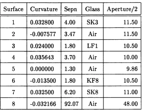
The most m ajor problematic area during the dawn of lens analysis concerned the copious numerical calculations required to trace finite, or real rays through even the most simple of optical systems. The data-m odel used to represent the system was of com para tively lesser importance, but is worth describing even briefly, since it forms the basis for subsequent work, and it also illustrates the simplicity and efficiency embodied within it. The table below illustrates the current industry accepted form at for presenting lens data, although no such standard actually exists. The rows are identified with the surfaces of a system, but for completeness the object, image and stop (sometimes called the iris) sur faces are often included. The first column gives the curvature (occasionally the inverse), the second is the inter-surface separation, the third is the refractive index or name of the inter-surface medium, and the final row is the sem i-aperture or occasionally the full diameter. There are other variations of data-table designed to encompass the specific d a ta entry requirements of any particular program, although the differences are quite minor.
Surface Curvature Sepn Glass A perture/2
1 0.032800 4.00 SK3 11.50
2 -0.007577 3.47 Air 11.50
3 0.024000 1.80 L F l 10.50
4 0.035643 3.70 Air 10.00
5 0.000000 1.30 Air 9.86
6 -0.013500 1.80 KF8 10.50
7 0.032500 6.20 SK8 11.00
8 -0.032166 92.07 Air 48.00
Table 1.1: Example Lens Data-Table (Kingslake Tessar)
curvature of the surface is given by Cn and the refractive index of the glass following the surface is r i j . This notation corresponds very closely to th a t which one would intuitively expect from the spreadsheet data-table in Table 1.1.
1.2
H an dlin g C o m p lex ity
The emphasis th a t has so far been placed on the visual presentation of d a ta and its corre spondence to the internal model has, for the past 50 years atleast, been of little consequence to most lens designers. After all, when the activity of lens design once involved numer ous individuals employing slide-rules or electromechanical calculators in order to trace ju st a few skew rays, then any modern lens design program might be greeted with much joy and celebration, particularly in the knowledge th a t productivity could be increased a thousand-fold. But, in the intervening years optical systems have steadily grown in com plexity, and the ability to create and manipulate these systems has been compromised by the shortcomings inherent in the human - com puter interface.
Nowhere does this become more apparent than in the design of the high resolution spectrograph. The reason why this is so stems from the underlying lack of axial symmetry th a t these systems exhibit. Consider the optical train comprising three cross-dispersing prisms th a t are to be found in the UCLES[1] spectrograph. There are six surfaces, each tilted with respect to any other, and there is a complete absence of any optical axis; the la tter point results in five of these surfaces also being assigned décentrations. The lens designer is faced with an enormous task ju st to set up this configuration. If the requirement dictated a double-pass through this sub-system, then the difficulty faced by the lens designer increases enormously.
1.3
A N ew V iew p o in t
At the heart of these problems lies the surface-based model, and particularly a sequential surface-based model. A sequential model requires th a t ray-tracing progresses from one surface to another, in the same way th a t one surface follows another surface in the lens
data-table. Sequential ray-tracing may only proceed from one surface to another surface th a t occupies the next row lower down the data-table. Any other sequence is not perm itted, and so surface groups th a t are in double-pass have to be recreated further down the table.
the novice or apprentice optical designer who cannot make the transition into the 3D world of the imagination, for it is the ability to view an optical system through the m ind’s eye th a t ultimately determines the degree of success one has in modelling it. P uttin g it another way, the surface-based model is akin to viewing this paragraph as a sequence of characters, while the component-based model puts emphasis on the character groups th a t we know as words. The former interpretation offers the com puter word processor the greatest advantage when m anipulating text, but it is the latter interpretation th a t is of the greatest benefit to the human reader. Taking this analogy one step further, it appears th a t current lens models have been designed to conform to machine interfaces and software practices th a t have been prevalent from the 1950s, and onwards; no attem p t has been made to alter this model to make it conform to the most modern software practices of today, nor has the human-computer interface been satisfactorily improved upon. It is not a coincidence th a t a t the time of writing, some modern com puter languages have been radically updated to include theories of object oriented programming (O OP). It is this paradigm shift th a t makes the world of objects accessible, and we shall see in later chapters how it can be put to use in creating a practical and intuitive model of an optical system.
C h a p t e r 2
L e n s M o d e l l i n g
Probably the most significant feature th a t separates human beings from the rest of the animal kingdom is the capacity and functionality of the brain. One of the higher level functions of a brain is the construction of a world model in which the organism, be it human or not, may operate in a manner th a t is both efficient and productive, where the latter implies th a t the organism will survive the trials of life and so reproduce. In so doing the organism will ensure the survival of its genes and th a t of its species. In man, the world model is more advanced and complex than th a t of any other creature. It has reached such a level of sophistication th a t it has allowed mankind to transfer conciousness into the surrounding environment. The manner in which we see this manifested is through the diverse ways in which order has been forced onto a world where none was evident before. Society and even civilisation itself has arisen from m an’s need to create order and to witness reflections of his own self. All these aspects of order may also be considered as world models th a t have stood the test of time, since it is the wide and popular acceptance of a model th a t ensures its long term survival. The success of any model ultim ately depends upon how well it serves its purpose. Models exist to bind together individuals in a common purpose, to enable meaningful and sophisticated communication, or to provide a framework for abstract exploration.
theories th a t relate to how such a system or phenomenon operates. W hether it succeeds in this task or not, it does not necessarily invalidate the original premises of th a t model. Either way, the model is shown to be robust or it is modified. In the long term , most models can be shown to undergo some degree of evolution. This is only natural and expected. Alternatively, a model may be used as a basis for calculation and extrapolation. Such models are prevalent throughout our society. To name ju st a few, we have economic models, population models, ecological models and galaxy formation models. In some of these cases the mechanisms involved are well understood, b ut in other cases there may be factors th a t are either ill-defined or unknown.
A com putational model is a description of a system th a t is embedded in software, and as such is limited by the capabilities of the underlying operating system and the com puter language employed. In addition, it may also be developed in such a way as to allow the model to be extended into unforeseen territories. The range and extensibility is ultim ately determined by the starting point, which is the crux of this thesis. The following sections throw light on the two principal models th a t relate to an optical system, highlighting their capabilities, weak points and strong points.
2.1
R eq u irem en ts
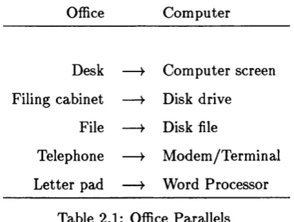
Any modern com puter application has some basis in a model if it is to operate in a meaningful manner. At the simplest level, the very architecture of the operating system behaves as a surrogate model. Present-day operating systems such as those based on Microsoft Windows or IBM O S/2 endeavour to create a graphical environment th a t may be intuitively understood in term s of an olfice or personal desk-top. This environment was adopted in preference to any other because the original developers recognised th a t people who are involved in creative work are also office-bound or desk-bound individuals. The domain over which these people usually operate extends to their office furniture, and the function of the operating system is to create an environment similar to th a t which the com puter user is already immersed in. Thus we can see several parallels between entities th a t exist in the office and those th a t exist on the com puter screen, as Table 2.1 shows.
Office Com puter
Desk — > Com puter screen Filing cabinet — y Disk drive
File — y Disk file
Telephone — y M odem /Term inal Letter pad — y Word Processor
Table 2.1: Office Parallels
organisation of the basic functional elements of the operating system conformed to an ob ject model as described above. While Windows offered the user new and simpler ways to interact with software, it proved to be a difficult environment to program for. The reason why this should be so stems from the structure of the supporting code th a t Windows pro vided in the form of library routines th a t were made accessible to developers. Requiring many tens of man-years to develop, the Windows operating system was coded entirely in a language called C% which a t the time had absolutely no facilities for object oriented programming. The result is th a t the simplest of tasks required many lines of code. Even today, programmers still refer to having had to write several hundred lines of ‘C ’ code in order to open a window and write ‘Hello’ inside it. Amongst other things, w hat Windows lacked was the ability to encapsulate d a ta and function, which is the first prerequisite for an object oriented language.
R ather than rewrite Windows in an O OP style, which would have been a terrific undertaking, Microsoft and Borland (two of the leading proponents of the object oriented approach) subsequently employed true OOP languages like C-|—1- and Borland Pascal to encapsulate the original ‘C ’ code and reformulate Windows into a new framework. Mi crosoft called this framework MFC (Microsoft Foundation Classes) and Borland called their framework OWL (O bject Windows Library). Both models allowed developers to interact with the Windows operating system in a more intuitive and structured manner, and more im portantly in an efficient manner. Thus the traditional ‘Hello’ program could now be w ritten in around a dozen lines of code.
internal model. This leads us to a few key points one may make regarding the nature of a com puter model:
1. the visual aspect of the model must reflect a familiar environment;
2. the visual interface must be in context;
3. the user must be allowed to interact meaningfully with the environment of the ap plication;
4. the underlying object model must closely conform to the visual description;
5. the object model must reflect the behaviour of the real-world model, a t the graphical level and preferably the d a ta level also;
6. the object model must be capable of extension.
The first three points concern the nature of the user interface and its applicability to the task a t hand, whilst the two points th a t follow are concerned with the accuracy and integrity of the model. The final point reminds us th a t a model may be a transitionary one, and th a t at some time later it may require to be modified in order to conform with some new understanding or behaviour th a t is to be im parted to the model.
2.2
T h e Surface-B ased M od el
Largely due to its simplicity and efficiency, the surface-based model (or SBM) has domi nated the world of optical analysis and design programs. A nother reason why it has pre vailed over the years is due to the limitations imposed by the various com puter languages th a t have been employed to develop these applications. Languages such as FORTRAN, Basic, Pascal and ‘C ’ provide only basic functionality for d a ta abstraction, while combined d a ta a n d function encapsulation is completely absent. T h at is not to say th a t it is im possible to achieve this goal using any of these procedural languages, but th a t attem pting
The implementation of a SBM can never be unique, since it is intimately dependent upon the machinations of the developer, which are themselves determined by culture, background and ability. Never-the-less, in order to dem onstrate how the SBM might be constructed, the author has chosen a system th a t, hopefully, will be generally accepted by most readers. Thus, consider a record structure called TSurf ace th a t embodies within it the essential characteristics of a spherical surface, and which can be described by the
following type declaration:
T S urface = r e c o rd
ap : d o u b le ; (♦ a p e r tu r e
O
cv : d o u b le ; (* c u rv a tu re
O
ndx : d o u b le ; (* p r i o r r e f r a c t i v e index *) sep : d o u b le ; (* p o s t s u rfa c e s e p a r a tio n *) end;
In addition, let us declare new types th a t describe a ray of light and a lens system:
TRay = re c o rd
x , y , z : d o u b le ; (* p o s i t i o n c o o r d in a te s *) l,m ,n : d o u b le ; (* d i r e c t i o n c o s in e s *) wvl : d o u b le ; (* w av elen g th *) end;
TLensSystem = a r r a y [ 1 . .M axSurfaces] o f T S u rface ;
. . . where the lens system is seen to be comprised of an array of surfaces.
In support of these basic entities it is necessary to have various functions and pro cedures th a t will undertake to perform the various operations and transform ations th a t characterise an active optical system. As an example, consider the case of ray-transfer, which is the process whereby the intersection of a ray of light with a surface is determined.
v a r
x t , y t , F , G, c o s i , d e l t a : e x te n d e d ; b e g in
(* tr e m s f e r to th e ta n g e n t p la n e *)
x t := r a y .x + ( s u r f .s e p - r a y .z ) * ( r a y . 1 / r a y . n ) ; y t := r a y . y + ( s u r f .s e p - r a y .z ) * ( r a y .m /r a y .n ) ;
(* tr e u is f e r to th e s u r f a c e *) F := s u r f .c v * ( s q r ( x t ) + s q r ( y t ) ) ;
G := r a y .n - s u r f .c v * ( r a y . l * x t + ray .m * y t ) ; c o s I := s q r t( s q r ( G ) - s u r f .c v * F ) ;
d e l t a := F / (G + c o s i ) ;
(* s e t th e ra y i n t e r s e c t i o n c o o rd in a te s *) r a y .x := x t + r a y . l * d e l t a ;
r a y . y := y t + ray.m * d e l t a ; r a y . z := r a y .n * d e l t a ; end;
In its simplest form, we can also consider the process of ray propagation through an optical system to be adequately described by the following code fragment:
f o r k := 1 t o MaxRays do b e g in
f o r j := 1 t o M axSurfaces-1 do b e g in R a y T ra n sfe r( s u r f [ j ] , ra y [k ] ) ; Ray Ref r a c t ( s u r f [ j ] , ra y [k ] ) ; end;
(* t r a n s f e r t o th e image p la n e *)
R a y T ra n sfe r( s u rf[M a x S u rfa c e s ], ra y fk ] ) ; end;
. . . where Ray Refract () is a procedure th a t accepts both surface and ray argum ents, ju st as Ray Transfer, and transform s the ray argument to conform to the new refracted ray.
Surface C urvature Sepn Glass Diam eter
1 0.086318 0.70 Ge 10.50
2 0.070305 10.33 Air 10.20
3 0.146526 0.50 Ge 6.30
4 0.115933 3.32 Air 6.20
5 0.000000 0.00 Air 1.00
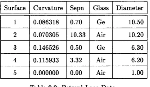
Table 2.2: Petzval Lens D ata
th a t though the process of refraction may be associated with a ray interacting with a refractive index boundary represented by a surface, the above code does not make any such distinction. Similarly, the process of ray transfer is a function of the space between two surfaces, but here again the subtlety is lost. In other words, the surface-based model cannot represent in code w hat we intuitively perceive to be happening.
It is not ju st a t the level of code th a t the above disparity is apparent, but also a t the level of the user interface. Consider the usual form in which lens d a ta is presented, either for inspection or for editing. Table 2.2 represents a simple Petzval lens of the type com monly used in infra-red imaging, comprising two separated single lenses of Germanium. For the purpose of dem onstration, let us attem p t to reverse the order of the two singlet Germanium lenses by swapping surfaces 1 and 3, and surfaces 2 and 4, resulting in Table 2.3. Inspection of this new table reveals th a t while the order of the lenses has indeed been
Surface Curvature Sepn Glass Diam eter
1 0.146526 0.50 Ge 6.30
2 0.115933 3.32 Air 6.20
3 0.086318 0.70 Ge 10.50
4 0.070305 10.33 Air 10.20
5 0.000000 0.00 Air 1.00
Table 2.3: Petzval Lens D ata
form at is adhered to then such surface exchanges will lead to spurious results. We say th a t the table representation of a lens system is not com mutative with row exchanges, which implies th a t the surface-based model is also non-commutative.
We may draw three conclusions based upon the above analysis of the surface-based model:
1. In term s of coding effort, the SBM is an efficient model;
2. The visual interface (spreadsheet) is a familiar one;
3. The SBM does not conform to our intuitive understanding of a lens system.
Both Items 1 and 2 are, w ithout a doubt, strong reasons for adopting this approach. T hat is not to say th a t we should be complacent and restrict our attem pts to improve upon this model. Indeed, the spreadsheet has, over the years, been endowed with ever-more useful features such as embedded drop-down list boxes (useful for the selection of glass types) and graphical cells th a t can show an image of a surface profile. These features all add to the functionality of the spreadsheet which in turn aid the user in inputting d a ta and comprehending the system th a t is entered. Item 3, on the other hand, tells us th a t this interface is only an abstract and not ideal representation of a lens system. In addition, neither is it possible to visualise the system by casual inspection, nor can it be manipulated in a similar manner as a real lens system might.
2.3
T h e C o m p on en t-B ased M od el
The essential idea behind all object modelling is th a t of abstraction, th a t is, a model th a t provides the required functionality and d a ta encapsulation while hiding the unnecessary details th a t can be overlooked by the user. Ideally, a model will make visible those aspects of a system which it is designed to express. In this regard the component-based model (or CBM) can be viewed as expressing a higher level of complexity when compared to the SBM, and this becomes evident to the user by the provision of a truly graphical interface to the layout of the lens system and a greater facility for system synthesis.
som e form of im aging quality, in th e m odel to be described a lens rep resen ts an a b s tra c t
elem ent t h a t m ay be a m irro r, a diffraction g ra tin g or even a light source. In fa ct, th e
a b s tra c t lens m ay represen t any physical e n tity t h a t one m ight asso ciate w ith th e m a jo r
elem ents of any im aging sy stem .
In o rd er t h a t th is lens be m anifested to th e user, it becom es necessary to im bue it
w ith som e form of g raphical q u ality th a t distin g u ish es it from any o th e r lens. In W indow s
p ro g ram s it is q u ite com m on for m inim ised executables or p ro g ram s to be rep resen ted by an
icon having som e m an n er of g rap h ic depicted w ithin its bounds. In doing so, th e underlying
p rogram is effectively anno u n cin g its presence to th e user, and d istinguishes itself from
any o th e r p rogram by th e uniqueness or c h a ra c te risa tio n afforded by its grap h ical icon.
Sim ilarly, a lens m ay have a picture-icon t h a t suggests t h a t th e lens is a m irror, a singlet
lens or a source, as th e following F igure 2.1 shows.
*
F ig u re 2.1: T h e D oublet-L ens Icon
T h e re is obviously m ore to th e lens icon th a n its sim ple arra n g e m e n t of coloured
pixels. In much th e sam e way as th e visible p o rtio n of an iceberg is a p o rte n t of so m eth in g
m uch larg er (and occasionally sinister) below th e waves, th e lens icon is sim ply th e visible
m an ife sta tio n of an o b je c t t h a t en cap su lates far m ore d a ta and inform ation th a n it is
possible to re p resen t graphically. B u t th e im p o rta n c e of th e icon is t h a t it isolates th e
lens in space {viz. - th e c o m p u te r screen) an d prom ises o th e r b eh av io u r (which will be
discussed la te r in th is section) m ore in tu n e w ith a physical entity, as opposed to th e ra th e r
com plex and n o t-so -in d ep e n d en t surface re p resen ta tio n of a row in a sp re ad sh eet.
In ad d itio n to th e g raphical n a tu re t h a t has been a ttr ib u te d to a lens, we can
also consider how a lens sy stem , com prising several individual lens co m p o n en ts, m ay be
re p resen ted . A gain, we borrow from th e m any graphical s tru c tu re s t h a t th e W indow s
e n v iro n m en t provides, and note th a t a class called TForm (generally know n as a window)
exists which ac ts as a co n tain e r or c o n ta in m e n t vessel for o th e r W indow s elem ents such
as b u tto n s and labels. T h e fa ct th a t TForm has p ro p e rtie s th a t enable it to identify and
"XL
SYSTEM1
&
- •
A
1
; .
-...
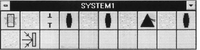
F ig u re 2.2: T h e L ens-System C o n ta in e r
F ig u re 2.2 show s such a form ac tin g as h o st for several differing lens ty p es, including a
source (top-left) and a prism (th e eighth from th e left on th e to p row ). T h e o rd e r of
c o m p o n en ts w ithin th e sy stem , or th e directio n in which light travels, com m ences from
th e top -left an d prodeeds to th e rig h t, and continues a t th e left-m ost co m p o n en t of th e
following row, an d so on.
A sim ple d escrip tio n of a lens co m p o n en t is given below:
TLensIcon = object
picture : TIcon; (* picture icon *)
lens : TLens; (* lens object *)
end;
TLensIcon is a class t h a t en c ap su lates tw o o th e r o b je c ts, TIcon and TLens, each of which is recognisably an essential elem ent of a lens-com ponent. In th e language of O O P , th ey
are also referred to as properties of TLensIcon. T h e picture p ro p e rty is th e icon t h a t is
visible on th e c o m p u te r screen, while lens is a reference to a generic lens d esc rip tio n . For
exam ple a singlet lens, as described below, is derived from a largely a b s tra c t class called
TLens, and so m ay be assigned as a lens p ro p e rty of TLensIcon.
TSingleLens = object(TLens)
surfacel : TSurface; (* first surface *) surface2 : TSurface; (* second surface *)
sep : TSpace; (* inter-surface space *)
glass : TGlass; (* glass type *)
procedure ProcessRays(rays : TRayArray); override; end;
Notice th a t the properties of the singlet lens are all familiar quantities, but in keep ing with the object paradigm they have been converted into new class descriptions th a t themselves encapsulate the required d a ta and functional properties of the abstracted en tities. One other noteworthy feature in the above class definition is the presence of a procedure called ProcessRays. This procedure accepts as a param eter an array of rays, which are then refracted and transferred from surface to surface until the rays are in a suitable form to be passed on to the next Lens component for processing. ProcessRays
is identified as a procedure associated with all classes derived from TLens, but since each newly derived lens component will interpret ProcessRays in a different manner, then this procedure will need to be re-coded to reflect this, hence the need to override the procedure for each descendent of TLens. Naturally, for simple refractive elements, the underlying code to ProcessRays is similar to th a t we have seen earlier in the previous section, i. e. RayTranfer and RayRefract.
In keeping with the previous section, we shall develop the necessary structures and code th a t describe a lens system and the manner in which rays are propagated from the source to the image plane. Firstly, a lens system may be described as an array of lenses, i. e.
TLensSystem = array[1..MaxLenses] of TLensIcon;
In practice, the TLensSystem would be described as a class having the array of
TLensIcon specified as a property of the class, again in accordance with the aim of de scribing all entities as class objects:
TLensSystem = object
MaxLenses : integer;
property Lens[n:integer] of TLens read GetLens write SetLens;
end;
The property description specifies th a t the identifier called Lens should be interpreted
assignment of Lens [ ] is handled. Thus a reference to the n*^ lens in a system called ALensSystem is given by ALensSystem.Lensfn]. W ith this information we can now write the code th a t implements raytracing in an object-based lens-system.
with ALensSystem do begin
for j := 1 to MaxLenses do Lens[j].ProcessRays(rays); end;
The im portant difference to note between this piece of code and th a t associated with the SBM is th a t the subject within the loop is of type TLens while in the SBM code it is the ray-transfer and refraction procedures. The OOP rendition of raytracing results in both subject and action being tightly bound to one another, as allowed by the class definition, but the purely procedural form shows no such tight binding. The reason why binding in these circumstances is so beneficial stem s from high degree of security th a t exists when employing methods th a t originate from and have been developed within the same class structure.
There are other ways in which the component-based model is superior to the surface- based model. Firstly, due to the similarity of structures th a t have been developed in code and th a t exist in the real world, it is possible for individual lenses to undergo physical transform ation in a manner th a t would be difficult to consider in the lower order SBM, As an example, take the case of lens reversal. In its im plementation we must develop reversal procedures for the surfaces first, and then introduce a reversal method for the lens itself, as the following code fragments indicate,
TSurface = object
x,y,z : double (* position *)
l,m,n : double (* orientation *)
glassl : TGlass (* prior glass ♦)
glass2 : TGlass (* post glass *)
procedure ProcessRays(rays : TRayArray); virtual; abstract;
procedure Reverse; virtual; abstract;
record the position and orientation of the surface, and glassl and glass2 are the glass types on either side of the surface boundary. Since we haven’t given TSurface any specific geometrical form, then the methods ProcessRays and Reverse cannot be properly defined and so are specified initially to be virtual and abstract methods. T h at is, they cannot be employed as is, but must be overriden and defined by a descendent class first. A descendent class might be TSphere, TAsphere or possibly TTorroid. Each descendent will have its own method of implementing these abstract methods of TSurface.
TSingleLens = object(TLens)
surfacel : TSurface; (* first surface *) surface2 : TSurface; (* second surface *)
sep : TSpace; (* inter-surface space *)
glass : TGlass; (* glass type *) procedure ProcessRays(rays : TRayArray); override;
procedure Reverse; override;
end;
This slightly modified version of the earlier TSingleLens now includes a Reverse
m ethod which is implemented below:
procedure TSingleLens.Reverse;
begin
Surfacel.Reverse ;
Surface2.Reverse ;
end;
Thus, assuming th a t the Reverse method for any particular surface type has been defined, then the reversal of any single-lens component is given by: ASingleLens.Reverse. The equivalent method for a set of surfaces within a SBM environment will not be as simple
Reverse in a SBM will require a process of inspection and the application of logical rules in order to isolate various lens combinations prior to implementing any lens transform ation. This procedure will be laborious and contrary to the methods th a t a lower order model should support or provide.
C h a p t e r 3
O b j e c t O r i e n t e d P r o g r a m m i n g
The last forty or so years has seen considerable development in the field of com puters and com puter architectures. In order to harness the ever increasing power th a t these hardware platforms provide requires programming languages to be regularly updated and improved.
Since the late 1970s when the 8-bit C P /M operating system prevailed, the advent of the IBM-PC has resulted in operating systems progressing from the 16-bit code of Windows
3.x
to the recent releases of the 32-bit operating systems, Windows NT and Windows 95.A t each stage of the operating system development cycle, new compilers and language enhancements have been required to match the new capabilities offered. The principal driving force behind this frenzy of activity is the goal of a fully object oriented system.
essence, w hat we have chosen to do is take w hat is most simple and efficient from the biological evolutionary process and applied it to a new set of com puter languages. These we have chosen to call ‘object-oriented’ languages.
O bject oriented programming, or OOP, represents the latest and most potentially rewarding paradigm shift since assembler language. Since the dawn of the com puter, man has sought to gain control over the massive computing power th a t lies dorm ant within the few square centimetres of silicon th a t is the playing field of the central processor. The central processing unit, or CPU, is inactive unless instructed otherwise. A com puter language is the means by which instructions are given to the CPU - ignoring for the moment the necessary intervention of the compiler. There have so far been four stages in the evolutionary process of the com puter language, where the emphasis of each has been placed upon a basic unit of d a ta an d /o r code. They are:
machine-code - this uses the native language of the CPU. Earh instruction normally comprises two parts: op-code and operand. The op-code indicates which operation is to be performed, while the operand supplies the necessary data;
assembly language - by replacing the machine language instruction with a mnemonic code and symbolic address, the task of writing a program is made easier. Prior to execution the assembler code requires translating to machine code;
procedural language - FORTRAN, Pascal, Basic and C are typical procedural (high-level) languages. Their overall structure is considerably closer to our everyday language and are much simpler to use. Structured programming methods are applicable to this class of com puter language as they all support procedural and modular code blocks.
object oriented language - there are two forms of object oriented languages; the pure O OP languages as typified by Smalltalk, and the hybrid types such as O bject Pascal, Ada and C-f-+. Both provide new constructs th a t support the necessary features of a OOP language (see later in this chapter).
• E n c a p s u la tio n — D ata and program code m ust be locatable within single entities. T h at is, an object must be able to store both d a ta elements (as a record struc ture does) and procedure elements (called methods). Procedural elements within an object must have autom atic access to d a ta elements within the object.
• I n h e r ita n c e — New object types must be able to be synthesised from existing ones by inheriting their attrib utes and method procedures.
• P o ly m o rp h is m — O bject methods must be callable w ithout respect for the actual object type in which the method resides. For example, the Show method performs radically different tasks when drawing a button control as opposed to drawing a grid control, though the call is identical. Also, provided they both descend from a common ancestor, calling the ancestor’s Show method using an instance of either the grid or button control should properly display the correct control.
• P r im a r y m e th o d o lo g y — The ob ject-orientation of a tool must be the primary method of constructing program code, not an afterthought or add-on.
The following sections will shed more light on the meaning and im portance of the first three of the above items, Borland’s implementation of O bject Pascal will be used to illustrate these features, though the code should also be familiar to C-|—t- and Ada programmers alike. Note: It is not possible in this chapter to convey to the reader all of the fin er details regarding object oriented prorogramming, but it is hoped that the general
points will come over and that the reader will seek further information in the bibliography.
3.1
E n cap su lation
Languages such as Basic and Pascal are typified by their clear discrimination between d a ta and procedural code-blocks. Virtually any program may be considered to possess a data-body th a t is subsequently processesed by numerous code-blocks and resulting in a
transform ation of the original data. The two entities remain separate at all times.
the simplest case these d a ta are bound to the type T V ector by the record, or structure, definition given by:
TV ector = r e c o rd X , y : r e a l ; end;
Let us declare a variable vec of type TV ector, then a reference to the vector coor dinates occurs using the dot notation, i. e. v e c .x and v e c .y . If now a procedure called le n g th is introduced which accepts a TV ector type as a param eter and returns the length of the vector, then it might be defined as follows:
f u n c tio n lengthC vec : TV ector ) : r e a l ; b e g in
w ith vec do
r e s u l t := s q r t ( x * x + y * y ) ; end;
. . . where a reference to the length of a vector is le n g th ( v e c ) . Now, one could argue th a t both the vector type and the function are intimately connected to one another since the function may only operate on vector param eters. This being so, one could also consider other functions and procedures th a t act only upon entities of type TV ector. Going one step further, could not a type be considered th a t bound both the vector and its supporting procedures into a new entity? Let us call this new entity an object and we shall refer to its definition as a class. TV ector is now a class, not a record, and is defined below:
TV ector = c l a s s X , y : r e a l ; ndims : i n t e g e r ; f u n c tio n l e n g t h : r e a l ; end;
function TVector.length : real;
begin
result := sqrt( x * x + y * y ) ;
end;
This class is similar in some respects to the earlier definition of the TVector record, and is accessed in a similar manner, i. e. the length of the vector vec, is given by
vec.length. Note how the length function no-longer requires a vector param eter to be passed as an argument. The reason for this is th a t since length is now embedded within the new class TVector it automatically has access to d a ta and other procedures declared within any instance of this class.
The process of melding both d a ta and data-related procedures into a new structure is called encapsulation, and is one of the core concepts of obect oriented programming. It arises through the recognition th a t programs almost always possess certain data-sets th a t appear to be bound to specific procedures, in the same way as we have seen with
TVector. A recognised practice during software development for identifying classes is to inspect the system model with a view to isolating nouns, such as vector, lens or ray, and then to assign methods th a t correspond to natural operations or transform ations th a t these classes would be employed in. For illustrative purposes the class TVector is shown below in a more complete form.
TVector = class
X , y : real;
ndims : integer;
constructor create;
procedure init(const a : array of real );
function length:real;
function cross( vec : TVector ) : TVector;
function dot( vec : TVector ) : real;
end;
Thus, if u ,v and w are vectors, then the scalar triple product u.{v X w) is given by u.dotC V .cross(w) ). Note the appearance of a new procedure with the title of
effect ^ which is the purpose of the constructor c r e a te . Given a variable vec declared to be of type TV ector then the creation of an instance of th a t type is through the state ment vec := T V e c to r.c re a te , and initialised by v e c . i n i t ( [ 1 ,2 ] ). The constructor and initialising procedure is given below:
c o n s tr u c t o r T V e c to r .c r e a te ; b e g in
i n h e r i t e d c r e a t e ;
{ th e v a lu e s o f x and y a r e by d e f a u l t e q u a l t o z e ro } ndims := 2;
p ro c e d u re T V ecto r. i n i t ( c o n s t a : a r r a y o f r e a l ) ; b e g in
X := a [0 ] ;
y := a [ l ] ; end;
It is clear from the above code how the array argum ent a[n] copies over to the internal variables x and y. The presence of the line i n h e r i t e d c r e a t e in the constructor is necessary to set aside the memory space for the declared variables and to maintain links to the declared functions for this class, as well as performing the necessary book-keeping chores th a t support all declared classes.
3.2
In h eritan ce
The previous section has dem onstrated the useful facility for creating new types called classes th a t enable the form and function of objects to be encapsulated into a single code block. If this reflected all there was to the much touted O OP paradigm then indeed there would be little benefit. To illustrate this point, consider developing a new class th a t is specific to three-dimensional vectors, and call this class TVectorS, It might be defined as follows:
TVectorS = class
X , y , z : real;
constructor create;
procedure init(const a : array of real ); function length:real;
function cross( vec : TVectorS ) : TVectorS;
function dot( vec : TVectorS ) : real;
end;
To complete this specification the above functions need to be rew ritten to account for the new type to which they belong, i. e.
function TVectorS.length : real;
begin
result := s q r t ( x * x + y * y + z * z ) ;
end;
The O OP vision is an organic one, where a class may be the progenitor of other, more complex, classes. In this regard, the above example fails to satisfy since there is no apparent inheritance mechanism in evidence during the definition of TVectorS. Since the three-dimensional vector has much in common with the two-dimensional vector, we would expect some degree of repetition in the code implementaion. W hat is required
is a mechanism th a t will allow TVectorS to be a descendant of TVector. In doing so, the various new methods might be updated in a similar manner, through inheritance. A clearer understanding will be obtained by re-writing the above example to include the new features for inheritance. Firstly we shall redefine the TVector class to make it suitable as an anscestor class.
TVector = class
X , y : real;
ndims : integer;
constructor create; virtual;
procedure init(const a : array of real );
function cross( vec : TObject ) : TVector; virtual; function dot( vec : TObject ) : real; virtual;
end;
There is one im portant addition to this new definition which is worth pointing out, and th a t is the presence of the directive virtual following each of the methods. This declaration indicates th a t the function may be overriden or redefined in a descendant class. Continuing on, a descendant of TVector is now defined th a t caters for three-dimensional vectors:
TVector3 = class( TVector )
z : real;
constructor create; virtual;
procedure init(const a : array of real );
function length:real; override;
function cross( vec : TObject ) : TVector; override;
function dot( vec : TObject ) : real; override; end;
It is with this new definition of a descendant class th a t inheritance features are evident. Firstly, the appearance of (TVector) following class states th a t TVectorS is a descendant of TVector. Secondly, the variables x and y are not present as they have been
inherited from TVector, and so only z is required to be declared; and thirdly, the m ethods th a t follow are to be redefined due to the inclusion of the directive override. Fortunately, inheritance can make this process simpler as the following two function overrides make clear:
constructor TVectorS.create;
begin
inherited create;
ndims := 3 ;
procedure TVectorS.init(const a : array of real );
begin
inherited init([ a[0],a[l] ]); z : = a [2] ;
end;
a n d ...
function TVectorS.length : real;
begin
result := sqrt( sqr( inherited length) + z * z );
end;
The procedures above illustrate the use of the inherited keyword, showing th a t the ancestor TVector is still visible to TVectorS, although the contrived use of inherited
in the length function is inefficient and so not appropriate nor absolutely required. One other interesting feature is the presence of TObj ect as the argum ent type in the functions
cross and dot where one would expect TVectorS in a class of the same type. Obviously a cross product cannot be envisaged between a vector and an object of unknown type, but this incongruity arises from the need to maintain an identical interface to both ancestor and descendant, when functions are to be over-ridden. This dilemma will be resolved in the next section.
3.3
P o ly m orp h ism
1. v a r
2. v e c l : T V ector;
S. vec2 : T V ector;
4 . vecS : TV ectorS;
5. l e n l . le n 2 , len S : r e a l ;
6. d o t : r e a l ;
7. b e g in
8. v e c l := T V e c to r .c r e a te ; 9. v e c l . i n i t ( [1 ,2 ] ) ; 10. vec2 := T V e c to rS .c re a te ; 11. vec2 . i n i t ( [1 ,2 ,S ] ) ; 12. vecS := T V e c to rS .c re a te ; IS . vecS. i n i t ( [ 1 ,2 ,S ] ) ; 14. l e n l := v e c l .l e n g t h ; 15. le n 2 := v e c 2 .le n g th ;
16. le n 2 := T V e c to rS (v e c 2 ).le n g th ; 17. lenS := v e c S .le n g th ;
18. d o t := v e c l . d o t ( vec2 ) ;
(* Wrong answ er *)
(* same v a lu e a s le n 2 *)
Lines 2—3 declare v e c l and vec2 to be of type TV ector while line 3 declares vec3 to be of type TVectorS, These three variables are then created and initialised in lines 8— 13. The point to notice here is th a t vec2 is created using the TVectorS constructor th a t is assigned to 3-dimensional vectors, while the vector is declared as a 2-dimensional vector. T h at this was possible indicates th a t the constructor was successful in creating the necessary memory resources and assigning the appropriate values to the vector variables.
vec2 to employ the 3-dimensionaI len g th -m eth o d . Finally, as one might expect, line 17 also results in a correct value being passed to len3.
The previous section concluded by noting th a t in order th a t equivalent methods should be available to all descendent classes, then the form of the method definition should remain unaltered. Thus, in the case of the do t-p ro du ct m ethod, the argum ent type is TObject in order to allow both 2-dimensional TVector and 3-dimensional TVectorS
param eters to be passed. Note: Object Pascal declares a typeTObject that is the prim itive ancestor o f all classes; in other words, TObject is to TVector as Adam is to Mankind. In achieving this compatibility across descendant classes, one must now ask how it is possible for a method to determine w hat kind of object has been passed as an argument, since we cannot speak meaningfully of a dot-product between a vector and a generalised object of unknown quantity.
RTTI, or run-time type information, is the means by which a class variable may be interrogated in order to ascertain its type. This is implemented in O bject Pascal by the new operators, is and as. As an illustration of this powerful enhancement to OOP languages (also recently axlded to C-t—|-), the length method for the TVectorS class is given below:
function TVectorS.dot(vec : TObject): real; begin
with vec as TVector do begin
if ndims >= S then
result := sqrt(x * vec.x + y * vec.y + z * vec.z)
else result := inherited dot(vec)
end;
end;
This new im plementation of the 3-dimensional dot method initially checks if the
will always be true), and then return the 2-dimensional dot-product, i. e.
function TVector.dot(vec : TObject):real;
begin
with vec as TVector do begin
if vec.ndims >= 2 then
result := sqrtCx * vec.x + y * vec.y); end;
end;
Such a cascading sequence of events allows for any size vector to be treated accordingly and correctly, whilst the exception is raised only in the event of a non-vector param eter being passed.