Bandwidth Enhancement Techniques of
Dielectric Resonator Antenna
ARCHANA SHARMA
Research scholar, Dept. of ECE, MANIT, Bhopal, India Email-er.archna.sharma@gmail.com
S.C. SHRIVASTAVA
Professor, dept of ECE, MANIT, Bhopal, India Email-scs_manit@yahoo.com
Abstract:
The paper briefly reviews the historical background of dielectric resonator antenna and its bandwidth enhancement techniques. The main focus is on a compact DRA that can offer broad band operation. It has been illustrated that dual resonance and multi resonance operation can be much effective to give wide band characteristics of DRA.
Index Terms - dielectric resonator antenna, broadband, multi resonance.
1. Introduction
Dielectric resonator as an antenna was proposed by professor S.A.Long in the early nineteen eighties[15]. Since the Dielectric resonator antennas (DRAs) are fabricated from low loss, temperature stable microwave dielectric materials and has negligible metallic loss, it is highly efficient when operated at millimeter wave frequencies. Conversely, a high permittivity or partially metalized dielectric resonator can be used as a small and low profile antenna operated at lower microwave frequencies. The Resonant frequency of DRA is a function of size, shape & permittivity.
The bandwidth of DRA depends on parameters such as the excitation method, shape, dimensional parameter & dielectric constant of DRA material. Over last decades, various bandwidth enhancement techniques have been developed for DRAs. This article is expected to offer antenna designers more direct design choice and guidance. In order to achieve the above objective, the paper first overviews several special features of DRAs , historical background on the basis of a survey and a collection of several scattered papers are presented, and finally discussions and conclusions.
2. Historical Background
the micro strip line, perpendicular feed, and lately, the convenient conformal-strip feed have been used. The waveguide fed dielectric resonator antenna was proposed, and reported that waveguide has a much lower feed line loss than other feeding methods .Recently, a dual function DRA filter(DRAF) that combines the DRA and DRF is investigated in 2008 and Slot fed wideband dielectric resonator for wireless application has been proposed in 2010 that enables the DRA for practical use.
3. Advantages of DRA
DRA can be integrable with MMIC circuits due to small size. There is no freq drift with temperature variation DRAs
DRAs can be fabricated in various shapes such as cylindrical, hemispherical rectangular, cylindrical Ring and have more design flexibility.
Fig. 1 Different shapes used for DRA
It is a low loss antenna due to low dissipation factor of dielectric materials.
It offers high gain & high efficiency due to absence of conductors and surface wave losses. It is a Volumetric Source and has good Radiation power factor.
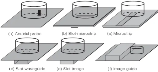
It can be excited by various feeds such as probes, slot, microstrip lines, dielectric image guides, coplanar lines and waveguide slot.
Fig. 2 Different excitation methods of DRA
4. Design Considerations for Wideband DRA
Optimization of the dielectric parameters and the feeding pattern need to be done to design compact & wideband DRA. The following are the different design considerations [1, 10, 11, 12].
Stub matching for micro strip feeding can be possible in slot coupled DRAs.
Introducing an air gap between the ground plane and dielectric resonator can increases the bandwidth. Reducing the permittivity of the dielectric resonator gives wideband operation.
Increasing the permittivity of the dielectric resonator enable high gain and low profile antenna design. Combining two different dielectric materials in a dielectric resonator antenna can be made.
Making a cavity backed dielectric resonator antenna to increase the gain and bandwidth.
Using hybrid antennas including the dielectric resonator antenna and a microstrip patch antenna, bandwidth can be widened.
DRA Substrate need to be thick and of low permittivity.
The resonant frequency of DRA is inversely proportional to square root of permittivity and hence it can be chosen properly for particular frequency range.
The size of the DRA also depends on inverse of permittivity of it. High permittivity DRA give compact design and high coupling while low permittivity DRA lowering the Q and hence increases bandwidth.
5. Methods of Bandwidth Enhancement
5.1 Single dielectric resonator antenna
The DRA of high permittivity has high Q factor and very small bandwidth which can be slightly increased by Single DRA design with Low permittivity that gives compact size with typical bandwidth of about 10%.The coupling is through the microstrip feed [Long S.A. et al(1983)].
Fig. 3 High permittivity Dielectric Resonator Antenna
5.2 Parasitic DRA
The combined effect of DRA and parasitic elements produce wideband operation. The individual BW of DRA is 5.8% while combined is around 17%.The gain is also improved due to parasitic elements. This technique has drawbacks of single feed so low coupling to parasitic elements and no matching network .It has high Volume [Petosa and A. Ittipibon 1998].
5.3. Multi segment DRA
MSDRA enhances the coupling to a micro strip line. Strong Coupling is possible due to high permittivity DR. Wide bandwidth is achieved by low permittivity DR. In the method High εr DR is inserted below Low εr DR for matching impedance of DRA. This technique can enhance the bandwidth up to 20 %.This method has the limitation of increased volume & weight [aldo petosa(2009)].
Fig. 5 Multi Segment DRA
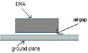
5.4.Introducing gap between ground plane and dielectric resonator antenna
By Introducing Gap between ground plane and Dielectric resonator antenna, Q-factor can be effectively reduced and exhibit a broader bandwidth. Bandwidth of around 30 % has been obtained. This method has drawback of large volume and Extra support [G.P. Junker et al 1994].
Fig. 6 Dielectric resonator with air gap between ground plane and DRA
5.5. Cavity backed DRA
A cavity is backed at the back of DRA to remove undesired back radiation and to increase gain. The bandwidth of the DRA is controlled by slot length & cavity size. It has the drawback of spurious modes due to metallic cavity and frequency drift with temperature variation [Kut Yuen Chow and Kwok Wa Leung (2000)].
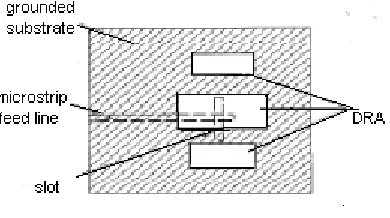
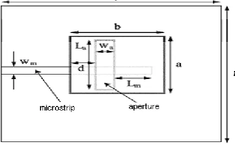
5.6Dual resonance method
The slot and DRA both radiates as a magnetic dipole and preserve the radiation patterns and polarization over the entire bandwidth. The method of fig. 8 combines a slot and DRA resonance and bandwidth of about 25 % has been achieved [8]. The dual resonance is very useful to design compact and wide band dielectric resonator antennas. The obtained width is not sufficient to use DRA for broadband operation in mobile communication and satellite communication. So band width can be further improved by multiple resonance technique and DRA arrays that can enable a DRA to be practically used for broadband applications [Amelia Buerkle et al.(2005)].
Fig. 8 Slot coupled DRA –Dual resonance characteristics.
5. Conclusion
Different p methods have been discussed to enhance the bandwidth of DRA. It is clear that low permittivity DRA with slot coupling gives more compact design with increased bandwidth due to dual resonance characteristics. Multiple resonance technique is useful for broadband applications. DRA arrays may be another technique to enhance bandwidth. Advantages of different methods can be merged together to attain much wider bandwidth. The hybrid DRA and orthogonal slot DRA with circular polarization may be optimized in future so that DRA can be a good candidate for satellite communication & mobile base stations.
References
[1] Aldo Petosa, Neil Simons et al., “Design and analysis of multi segment dielectric resonator antennas,” IEEE Trans. On Antennas
And Propagation, vol. 48, no. 5, pp. 738-742, May 2000.
[2] Atab ak Rashidian and David M. Klymyshyn, “On the two segmented and high aspect ratio rectangular dielectric resonator antennas
for bandwidth enhancement and miniaturization,” IEEE Transactions On Antennas And Propagation, vol. 57, no. 9, pp. 2775-2780, September 2009
[3] Amelia Buerkle et al., “ Compact slot and dielectric resonator antenna with dual resonance, broadband characteristics,” IEEE trans.
On Antennas and Propagation, vol.4, pp. 1020-1024, March 2005.
[4] G.P. Junker,A.A Kishk et al, “Effect of air gap on cylindrical dielectric resonator antenna operating in TM01 mode,” Electronics
Lettes,vol. 30,no. 3,pp 97-98,Jan 1994.
[5] Hisashi Morishita, Kazuhiro Hirasawa et al., “Analysis of a cavity-backed annular slot antenna with one point shorted,” IEEE Trans.
On Antennas and propagation, vol.39, no.10, pp. 1472-1478, October 1991.
[6] Kut Yuen Chow and Kwok Wa Leung, “Theory and experiment of the cavity-backed slot-excited dielectric resonator antenna,” IEEE
Trans. On Electromagnetic Compatibility, vol. 42, no. 3, pp .290- 296, August 2000.
[7] Long S.A. et al., “The resonant cylindrical dielectric cavity antenna,” IEEE Trans. Antennas Propagation, vol. 31, pp. 406–412, 1983.
[8] Mohamad I. Sulaiman et al, “A singly fed rectangular dielectric resonator antenna with a wideband circular polarization,” IEEE
Antennas And Wireless Propagation Letters, vol. 9, pp. 615-618, 2010
[9] M. Saed and R. Yadla, “Microstrip fed low profile and compact dielectric resonator antennas,” Progress In Electromagnetics Research,
PIER ,vol. 56, pp. 151–162, 2006.
[10] Petosa, A. Ittipibon, “Recent advances in dielectric-resonator antenna technology,” IEEE Antenna and Magazine, vol. 40, no. 3, pp.
35-43, June 1998.
[11] P. M. Hadalgi et al., “Slot fed wideband dielectric resonator for wireless application,” Indian Journal of Radio & Space Physics, vol. 39, pp.372-375, Dec 2010.
[12] Rajesh kumar Mongia et al., “Theoretical and experimental investigations on rectangular dielectric resonator antennas,” IEEE Trans.
On Antennas and propagation, vol. 45, no.9, pp. 1350-1355, Sept.1997.
[13] S.B. Cohn “Microwave band pass filters containing high Q dielectric resonators,” IEEE Trans. Microwave Theory Tech., vol.
MTT-31, pp. 1023 -1029, Dec. 1968
[14] S. K. Khamas, “Circularly polarized dielectric resonator antenna Excited by a conformal wire,” IEEE Antennas And Wireless
Propagation Letters, vol. 7, pp. 240-242, 2008.
[15] T.A. Denidni and Z. Weng, “ Rectangular dielectric resonator antenna for ultra wideband applications,” Electronics Letters, vol. 45,
no. 24, Nov. 2009.
[16] X. Q. Sheng et al., “Analysis of waveguide-fed dielectric resonator antenna using a hybrid finite element method,” IEE proc.
Microwave Antenna Propagation, vol. 151 , no. 1, Feb 2004.
[17] Yuan Gao,et al, “A compact Wideband Hybrid Dielectric Resonant Antenna”, IEEE Microwave and wireless components Letters,