University of Pennsylvania
ScholarlyCommons
Publicly Accessible Penn Dissertations
1-1-2015
Data-Driven Haptic Modeling and Rendering of
Realistic Virtual Textured Surfaces
Heather Marie Culbertson
University of Pennsylvania, [email protected]
Follow this and additional works at:http://repository.upenn.edu/edissertations
Part of theMechanical Engineering Commons, and theRobotics Commons
Recommended Citation
Culbertson, Heather Marie, "Data-Driven Haptic Modeling and Rendering of Realistic Virtual Textured Surfaces" (2015).Publicly Accessible Penn Dissertations. 1674.
Data-Driven Haptic Modeling and Rendering of Realistic Virtual Textured
Surfaces
Abstract
The haptic sensations one feels when interacting with physical objects create a rich and varied impression of the objects, allowing one to gather information about texture, shape, compressibility, and other physical characteristics. The human sense of touch excels at sensing and interpreting these haptic cues, even when the object is felt through an intermediary tool instead of directly with a bare finger. Dragging, pressing, and tapping a tool on the object allow you to sense the object's roughness, slipperiness, and hardness as a combination of vibrations and forces. Unfortunately, the richness of these interaction cues is missing from many virtual environments, leading to a less satisfying and less immersive experience than one encounters in the physical world. However, we can create the perceptual illusion of touching a real object by displaying the appropriate haptic signals during virtual interactions.
This thesis presents methods for creating haptic models of textured surfaces from acceleration, force, and speed data recorded during physical interactions. The models are then used to synthesize haptic signals that are displayed to the user during rendering through vibrotactile and/or kinesthetic feedback. The haptic signals, which are a function of the interaction conditions and motions used during rendering, must respond realistically to the user's motions in the virtual environment. We conducted human subject studies to test how well our virtual surfaces capture the psychophysical dimensions humans perceive when exploring textured surfaces with a tool.
Three haptic rendering systems were created for displaying virtual surfaces using these surface models. An initial system displayed virtual versions of textured surfaces on a tablet computer using models of the texture vibrations induced when dragging a tool across the real surfaces. An evaluation of the system showed that displaying the texture vibrations accurately captured the surface's roughness, but additional modeling and rendering considerations were needed to capture the full feel of the surface. Using these results, a second system was created for rendering a more complete three-dimensional version of the haptic surfaces including surface friction and event-based tapping transients in addition to the texture vibrations. An evaluation of this system showed that we have created the most realistic haptic surfaces to date. The force-feedback haptic device used in this system, however, was not without its limitations, including low surface stiffness and undesired inertia and friction. We developed an ungrounded haptic augmented reality system to overcome these limitations. This system allowed us to change the perceived texture and friction of a physical three-dimensional object using the previously-developed haptic surface models.
Degree Type
Dissertation
Degree Name
Doctor of Philosophy (PhD)
Graduate Group
First Advisor
Katherine J. Kuchenbecker
Keywords
haptics, textures, virtual reality
Subject Categories
DATA-DRIVEN HAPTIC MODELING AND RENDERING OF
REALISTIC VIRTUAL TEXTURED SURFACES
Heather M. Culbertson
A DISSERTATION
in
Mechanical Engineering and Applied Mechanics
Presented to the Faculties of the University of Pennsylvania in Partial
Fulfillment of the Requirements for the Degree of Doctor of Philosophy
2015
Katherine J. Kuchenbecker, Supervisor of Dissertation
Associate Professor, Department of Mechanical Engineering and Applied Mechanics
Prashant Purohit, Graduate Group Chairperson
Associate Professor, Department of Mechanical Engineering and Applied Mechanics
Dissertation Committee:
Mark Yim
Professor of Mechanical Engineering and Applied Mechanics
Katherine J. Kuchenbecker
Associate Professor of Mechanical Engineering and Applied Mechanics
Daniel D. Lee
Professor of Electrical and Systems Engineering
Yon Visell
ACKNOWLEDGMENTS
Finishing this thesis would not have been possible without the love and support
of so many people in my life. First I would like to thank my advisor, Katherine J.
Kuchenbecker, for her encouragement and support over the last five years. I have
been extremely lucky to work with her, and she has always pushed me to be the
best researcher and engineer I can be. She has been an inspiration to me in her
dedication and skill in both research and teaching, and I hope to one day to follow in
her footsteps and become a professor.
It’s been a honor to work will all of the members of the Penn Haptics Group.
Thank you for always making me feel welcome in lab and making it such a fun place to
work. Even though many lab members have come and gone over the years, know that
each of you have touched my life and my research in some way. A special thank you
to Joe Romano, Pablo Castillo, Ben Goodman, Tim Herrman, Raven Hooper, Nick
Pesta, Ettie Unwin, Craig McDonald, Juanjo Lopez Delgado, and Shweta Krishnan
who have worked with me on several projects over the years.
I would especially like to thank Rebecca Pierce for her support and encouragement
over the last five years. Thank you for giving me countless opportunities to bounce
ideas off of you, while simultaneously reminding me of when it is time to step away
from the research and come back to it later with a clear head. Thank you for being
such a caring and wonderful person, and for reminding me what is really important
I also owe a great deal to my high school science teacher, Don Rotsma, who
convinced me to take his physics class when I was hesitant that I could handle the
topic. This class really started my love for engineering and mechanics, and without
it my life trajectory would have been very different. Thank you for fostering in me
such a passion for science that has really molded the rest of my life.
Finally I would like to thank my family, without whose love and support this thesis
would not have been possible. Mom, thank you for supporting me in my decision to
move across the country for graduate school and for never stopping to believe in me
and my dreams. You have been my personal cheerleader for as long as I can remember
and I could not have done this without your unflagging encouragement. Dad, thank
you for fostering in me a love of building and creating as a child. Although I wish
you were still here to share this moment with me, I know that you are watching with
pride from heaven. Daniel, you are the best big brother I could have asked for. Thank
you for always being there for me and sharing my love of all things nerdy.
The research presented in this thesis was generously supported by a grant from
the National Science Foundation. My graduate studies were funded through research
fellowships from the Department of Mechanical Engineering and Applied Mechanics
at the University of Pennsylvania and the National Science Foundation Graduate
Research Fellowship Program. These fellowships have given me invaluable freedom
ABSTRACT
DATA-DRIVEN HAPTIC MODELING AND RENDERING OF REALISTIC VIRTUAL TEXTURED SURFACES
Heather M. Culbertson
Katherine J. Kuchenbecker
The haptic sensations one feels when interacting with physical objects create a
rich and varied impression of the objects, allowing one to gather information about
texture, shape, compressibility, and other physical characteristics. The human sense
of touch excels at sensing and interpreting these haptic cues, even when the object
is felt through an intermediary tool instead of directly with a bare finger. Dragging,
pressing, and tapping a tool on the object allow you to sense the object’s roughness,
slipperiness, and hardness as a combination of vibrations and forces. Unfortunately,
the richness of these interaction cues is missing from many virtual environments,
leading to a less satisfying and less immersive experience than one encounters in the
physical world. However, we can create the perceptual illusion of touching a real
object by displaying the appropriate haptic signals during virtual interactions.
This thesis presents methods for creating haptic models of textured surfaces from
acceleration, force, and speed data recorded during physical interactions. The models
are then used to synthesize haptic signals that are displayed to the user during
ren-dering through vibrotactile and/or kinesthetic feedback. The haptic signals, which
human subject studies to test how well our virtual surfaces capture the psychophysical
dimensions humans perceive when exploring textured surfaces with a tool.
Three haptic rendering systems were created for displaying virtual surfaces
us-ing these surface models. An initial system displayed virtual versions of textured
surfaces on a tablet computer using models of the texture vibrations induced when
dragging a tool across the real surfaces. An evaluation of the system showed that
displaying the texture vibrations accurately captured the surface’s roughness, but
additional modeling and rendering considerations were needed to capture the full
feel of the surface. Using these results, a second system was created for rendering
a more complete three-dimensional version of the haptic surfaces including surface
friction and event-based tapping transients in addition to the texture vibrations. An
evaluation of this system showed that we have created the most realistic haptic
sur-faces to date. The force-feedback haptic device used in this system, however, was
not without its limitations, including low surface stiffness and undesired inertia and
friction. We developed an ungrounded haptic augmented reality system to overcome
these limitations. This system allowed us to change the perceived texture and friction
of a physical three-dimensional object using the previously-developed haptic surface
Contents
1 Introduction 1
1.1 Human Tactile Sensing . . . 3
1.2 Touch Modalities . . . 6
1.3 Haptic Interfaces . . . 7
1.4 Thesis Overview and Contributions . . . 10
2 Recording and Modeling of Haptic Textures 14 2.1 Prior Work in Texture Modeling . . . 16
2.2 Recording the Feel of a Texture . . . 19
2.2.1 Data Collection System . . . 20
2.2.2 Data Collection Procedure . . . 22
2.2.3 Data Processing . . . 22
2.2.4 Texture Samples . . . 24
2.3 Texture Modeling . . . 25
2.3.1 Model Structure . . . 25
2.3.2 Data Segmentation . . . 26
2.3.3 Creation of Texture Model Set from Segments . . . 28
2.3.4 Model Storage . . . 30
2.4 Generating Vibration Signals . . . 32
2.4.1 AR Model Interpolation . . . 32
2.4.2 Signal Synthesis . . . 35
2.5 Method Evaluation . . . 36
2.5.1 Spectral Difference Metric . . . 36
2.5.2 Spectral Differences Across Materials . . . 38
2.5.3 Spectral Differences Across Subjects . . . 39
2.5.4 Spectral Differences Across Materials and Subjects . . . 40
2.6 Summary . . . 44
3 Rendering and Evaluation of Haptic Textures 45 3.1 Rendering Vibration Signals . . . 46
3.1.1 Tablet System . . . 46
3.1.3 Rendering Hardware . . . 48
3.2 Texture Samples . . . 48
3.2.1 Roughness Measurements . . . 49
3.2.2 Surface Stiffness Measurements . . . 50
3.2.3 Friction measurements . . . 51
3.2.4 Fineness Measurements . . . 51
3.3 Human Subject Study . . . 52
3.3.1 Experimental Set-up . . . 52
3.3.2 Experimental Procedure . . . 53
3.3.3 Results . . . 56
3.3.4 Discussion . . . 64
3.4 Summary . . . 67
4 Three-Dimensional Rendering of Haptic Surfaces 69 4.1 Background . . . 72
4.2 Surface Modeling . . . 77
4.2.1 Modeling Friction . . . 77
4.2.2 Modeling Tapping Transients . . . 80
4.2.3 Modeling Texture . . . 82
4.3 Surface Rendering . . . 85
4.3.1 Rendering Friction . . . 86
4.3.2 Rendering Tapping . . . 87
4.3.3 Rendering Texture . . . 88
4.4 Choosing Distinct Surfaces . . . 90
4.4.1 Friction Estimation . . . 91
4.4.2 Tapping Transient Estimation . . . 91
4.4.3 Roughness Estimation . . . 91
4.4.4 Surface Clustering . . . 92
4.5 Human Subject Study: Responsiveness to User Force and Speed . . . 93
4.5.1 Experimental Set-up . . . 94
4.5.2 Experimental Procedure . . . 95
4.5.3 Results . . . 99
4.5.4 Discussion . . . 105
4.6 Human Subject Study: Friction, Tapping and Texture . . . 111
4.6.1 Experimental Set-up . . . 111
4.6.2 Experimental Procedure . . . 112
4.6.3 Results . . . 114
4.6.4 Discussion . . . 122
5 Displaying Texture and Friction via Haptic Augmented Reality 130
5.1 Background . . . 133
5.2 Interaction Condition Measurements . . . 137
5.2.1 Hardware Description . . . 137
5.2.2 Force Threshold . . . 139
5.2.3 Position Measurements . . . 140
5.2.4 Force Measurements . . . 143
5.2.5 Analysis of Position Measurements . . . 144
5.3 Pen Design . . . 148
5.3.1 Design Considerations . . . 148
5.3.2 Tooltip Design . . . 149
5.3.3 Material Choice . . . 150
5.3.4 Dynamic Analysis . . . 151
5.3.5 Analysis of the Socket Design . . . 153
5.4 Augmented Textures . . . 155
5.4.1 Generating Textures . . . 156
5.4.2 Hardware . . . 156
5.4.3 Analysis . . . 157
5.5 Augmented Friction . . . 160
5.5.1 Friction Actuation Design . . . 161
5.5.2 Dynamic Analysis . . . 162
5.5.3 Characterizing the Solenoid . . . 165
5.5.4 Friction Control Scheme . . . 171
5.5.5 System Analysis . . . 174
5.6 Summary . . . 176
6 Conclusion 178 6.1 Contributions . . . 179
6.2 Future Directions . . . 182
A The Penn Haptic Texture Toolkit 185 A.1 Data Collection . . . 188
A.1.1 Texture Samples . . . 188
A.1.2 Included Data Files . . . 189
A.2 Haptic Texture and Friction Models . . . 190
A.2.1 Texture Models . . . 190
A.2.2 Friction Model . . . 193
A.2.3 Included Model Files . . . 193
A.3 Texture Rendering . . . 194
A.3.1 Hardware . . . 195
A.3.2 Software . . . 196
A.4 Summary . . . 199
List of Tables
1.1 Mechanoreceptors in the human hand [9, 52, 53] . . . 4
2.1 Spectral Differences Across Materials . . . 38
2.2 Spectral Differences Across Subjects . . . 41
3.1 Physical Measurements of Materials . . . 50
3.2 Correlation of Adjective Lines . . . 62
4.1 Rendering Conditions . . . 96
4.2 Comparison of Similarity to Texture Signal Behavior . . . 103
4.3 Correlation of Real Adjective Ratings . . . 116
4.4 Correlation of Virtual Adjective Ratings . . . 116
A.1 Recorded Data Files . . . 191
A.2 Model Resampling Files . . . 192
A.3 Model Files . . . 194
List of Figures
2.1 Haptic recording device. The tool measures position, orientation, force, and acceleration for three axes during interaction with texture samples. 20 2.2 A diagram of our data recording and processing system. Acceleration
and force are recorded at 10 kHz. Position and orientation are recorded at 240 Hz and upsampled to 10 kHz. A rotation matrix calculated from the orientation data at each time step is used to find the force vector and tooltip position vector in the world frame. The normal and tangential forces and tooltip speed are calculated and low-pass filtered. 23 2.3 Six textures that were haptically modeled with the presented
meth-ods. These materials were chosen to provide a set of textures that was diverse in roughness, hardness, slipperiness, and fineness of surface features. . . 24 2.4 A diagram of our texture modeling system. The acceleration signal
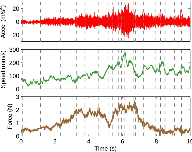
is fed into the segmenting algorithm, which returns the segmentation points and proposed AR order. An AR model is created for each seg-ment and labeled with the median force and median speed during that segment. The coefficients are converted to LSFs to ensure stability during rendering. Outlier AR models are determined and rejected as appropriate. The remaining AR models are stored in a Delaunay tri-angulation in force-speed space. . . 25 2.5 Recorded acceleration signal that was segmented using the AutoPARM
algorithm. Dotted lines represent the segment breakpoints. Force and speed were not used during the segmenting process, but they are shown to illustrate the motions the subject used during data capture. . . 29 2.6 Delaunay triangulation for the canvas model set. Each vertex
2.7 A diagram of our texture signal synthesis process using measurements of a user’s current position and force. The position data is differenti-ated and low-pass filtered to obtain the speed. A collision detection algorithm is run to determine where the user’s force and speed lie in the Delaunay triangulation. Barycentric coordinates are used to inter-polate between the LSFs and variance of the three AR models at the vertices of the triangle. The interpolated LSFs are transformed to AR coefficients. The coefficient and variance values are passed to our LPC signal generator, which creates an appropriate acceleration waveform. 32 2.8 Sample force-speed trajectory used during synthesis of vibrations. This
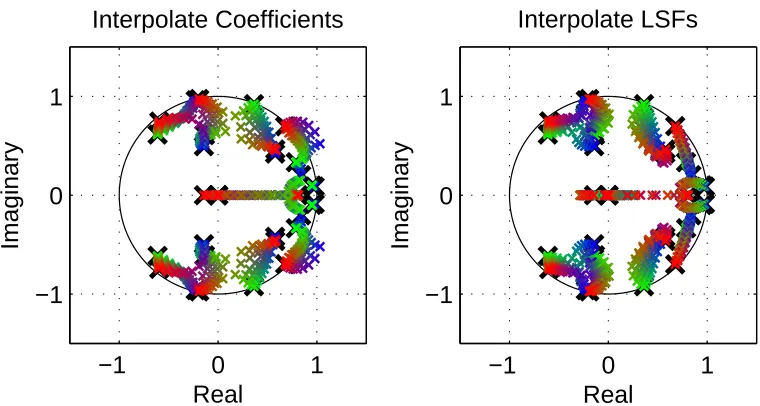
trajectory spans the range of forces and speeds typically used by indi-viduals when interacting with textures through a tool. . . 33 2.9 Loci of poles for interpolating between three models using (a)
coeffi-cients and (b) line spectral frequencies. When interpolating with the coefficients of the models, some poles travel outside the unit circle, re-sulting in a new unstable model. The line spectral frequencies ensure the stability of the model by requiring all poles to lie within the unit circle. . . 33 2.10 Recorded and synthesized data for comparison of texture model set
per-formance. The acceleration, force, and speed data were recorded from the canvas material using the haptic recording device. The recorded force and speed signals were then used to synthesize accelerations for all six materials. . . 35 2.11 Texture models for all subjects clustered quantitatively using the
spec-tral difference metric. Models were largely clustered according to ma-terial. Lines showing the perceptual qualities of roughness and fineness of surface features are displayed. . . 42
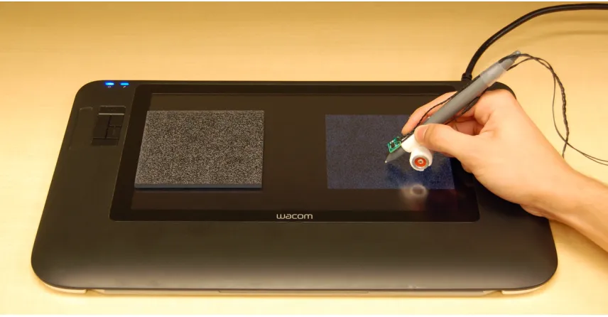
3.1 A diagram of our full texture rendering system. A texture vibration signal is synthesized using measurements of the user’s current position and force given by the Wacom tablet. This signal is then output via the computer soundcard, through a current amplifier, to drive the Haptu-ator on the stylus. The dashed red box separates the tablet hardware and output system. . . 46 3.2 Our texture rendering system. A force sensor in the stylus measures
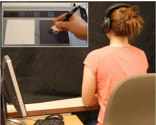
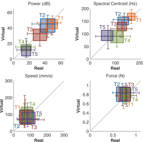
3.3 Experimental set-up. The subject sat in front of the tablet, across from the experimenter. A black curtain prevented the subject from seeing the textures, and headphones playing pink noise masked audio cues. The subject grasped the stylus augmented with a Haptuator in her dominant hand and interacted with real and virtual textures placed on the tablet screen. . . 54 3.4 Comparison of the power and spectral centroid of the recorded
acceler-ation signal and the speeds and forces used by subjects during the free exploration phase of the study. There is a strong linear trend for power and spectral centroid comparing values for the corresponding real and virtual textures. There is no statistical difference in the speeds and forces used by subjects on real and virtual textures. . . 58 3.5 Real and virtual textures placed in three-dimensional perceptual space
based on dissimilarity ratings. Lines showing the perceptual qualities of roughness, hardness, slipperiness, and fineness were fit to the space using ratings along the four adjective scales. . . 59 3.6 Comparison of dissimilarity ratings across the four types of texture
pairs. The median dissimilarity rating for the real-virtual same texture pairs is significantly lower than the median ratings for the three other types of pairs. . . 60 3.7 Dendrogram of materials showing clustering of real and virtual textures
using the distances between textures in three-dimensional perceptual space. . . 61 3.8 Comparison on subjects’ ratings of the ten textures along the four
ad-jective scales. The box plots for roughness and fineness show a strong linear trend in the ratings for the corresponding real and virtual tex-tures. The box plot for hardness shows a similar trend in the ratings, while the box plot for slipperines shows no correlation. . . 62 3.9 Normalized perceived vs. predicted dissimilarity. The perceived
dis-similarity is found using the disdis-similarity ratings averaged across all subjects. The predicted dissimilarity is found by performing multilin-ear regression on the average dissimilarity ratings using as predictors the pair-wise differences in the average ratings of textures along the four adjective scales. . . 64
4.1 Representation of a tool dragging along a surface in the Dahl friction model. The tool and a point on the surface are modeled as being connected by a spring. . . 78 4.2 Friction data for a sample material, MDF. The friction coefficient is
4.3 Recorded tapping transient accelerations for two sample materials. The amplitude of the vibrations depends on the incoming speed of the tool. The spectral content of the vibrations depends on the hardness of the surface. . . 81 4.4 Recorded tool acceleration, speed, and normal force signals from
drag-ging the recording tool across MDF in a circular motion. The accel-erations change as a function of the scanning speed and normal force used during the interaction. . . 83 4.5 Omni with Haptuator attached to the stylus tip. . . 90 4.6 Clusters of surfaces based on kinetic friction coefficient, tap response
factor, and power of texture vibrations. A subset of surfaces that spans the perceptual space represented by the original 100 surfaces was chosen by selecting one surface from each cluster. . . 92 4.7 The fifteen surfaces chosen from the cluster analysis to span the
per-ceptual space covered by the original 100 surfaces. . . 93 4.8 Experimental set-up. The subject sat at a table in front of a computer
and wore headphones playing pink noise to mask auditory cues. The subject used an Omni to feel the virtual surfaces and an adapted Omni handle to feel the real surfaces. . . 94 4.9 Sample texture vibration signals that were synthesized for the four
rendering conditions using the Nylon Mesh texture model. The force-speed trajectory was chosen to span the typical force-force-speed space ex-plored by subjects when feeling the surfaces. . . 97 4.10 Experimental set-up. The subject used a Phantom Omni with
Haptu-ator rigidly attached to the tip to interact with the virtual textures. . 99 4.11 Comparison of similarity ratings across the four virtual versions of each
surface (Condition FS: responds to force and speed; Condition F: re-sponds to force only; Condition S rere-sponds to speed only; Condition
φ: does not respond to force or speed.). Statistically significant differ-ences in similarity value from the control virtual surfaces are marked with a bar and asterisks (∗∗∗ ≡p≤0.001, ∗∗ ≡p≤0.01,∗ ≡p≤0.05).100 4.12 Comparison of the change in similarity between the control surface and
the three experimental conditions to the conditions’ spectral difference metric. . . 104 4.13 Comparison of the measured surface parameters to the subjects’ ratings
4.14 Comparison of the tap spectral centroid to the subject’s hardness rat-ings for the fifteen real surfaces. The tap spectral centroid was found to be a better predictor of rated hardness than the tap response factor. 115 4.15 Comparison of the subjects’ ratings of the control virtual surfaces to
their ratings of the fifteen real surfaces along the three adjective scales along the same scale. There is high correlation between the rated characteristics of the real and virtual surfaces for all three perceptual dimensions. . . 116 4.16 Real and virtual surfaces placed in three-dimensional perceptual space.
The real and control virtual surfaces are placed using their average ad-jective ratings. The remaining three virtual surfaces are placed by re-moving one modeling component (friction, tapping, or texture), which corresponds with the removal of one perceptual component (slipperi-ness, hard(slipperi-ness, or roughness). . . 117 4.17 Comparison of similarity ratings across the four virtual versions of
each surface. Statistically significant differences in similarity from the control virtual surface are marked with a bar and asterisks (∗ ∗ ∗ ≡
p≤0.001, ∗∗ ≡p≤0.01, ∗ ≡p≤0.05). . . 118 4.18 Similarity ratings for the condition with the highest average similarity
rating calculated separately for each surface. Although some rendering conditions resulted in higher average similarity than the control surface, none of these differences were statistically significant. . . 120 4.19 Relationship between the surfaces’ physical parameters and the percent
difference in similarity ratings resulting from the removal of the relevant modeling component. . . 121 4.20 Relationship between the average adjective ratings of the real surfaces
and the percent difference in similarity ratings resulting from the re-moval of the relevant modeling component. . . 122
5.1 The force/torque sensor system used to determine interaction condi-tions. (a) The sensor’s axes and origin. (b) An acrylic cube is rigidly attached to the sensor to serve as the physical object to be augmented with texture and friction. . . 138 5.2 Percentage of false contacts as a function of the force threshold level. 140 5.3 A diagram of our system for determining the user’s interaction
con-ditions on the augmented reality system. The user’s contact position is determined from a three-dimensional geometric model of the object and measurements of the applied force and torque. . . 141 5.4 Diagram illustrating how contact position is estimated from force and
torque measurements. . . 142 5.5 Free body diagram showing the two-dimensional case used to determine
5.6 Theoretical position repeatability estimated using error analysis of a simple one-dimensional case of the contact position calculations. . . . 145 5.7 Estimated tool position at different normal force levels. The amount
of noise in the position decreases as force is increased. . . 146 5.8 Distribution of position errors for static position measurements. The
distributions are the same in the x and y directions, indicating that position resolution is the same in all directions. . . 147 5.9 Tooltip socket design with four bearings. . . 149 5.10 (a) Simplified socket design used in analysis. (b) Free body diagram
of forces applied to the rolling ball. . . 151 5.11 Vibrations produced as the tool is dragged over a smooth surface. . . 155 5.12 Comparison of commanded and measured accelerations for two materials.157 5.13 Calculated tooltip trajectories when vibrations were playing and when
they were turned off. The DFT of the two trajectories indicates that the calculated tool position is not affected by the presence of external vibrations. . . 159 5.14 Design of haptic augmented reality pen. It can alter the perceived
tex-ture of a physical object by displaying textex-ture vibrations through the Haptuator. The friction between the pen tip and object is modulated using a braking force applied to the metal ball by the solenoid. . . 160 5.15 Full haptic augmented reality system. An object is rigidly attached
to the force sensor, which provides measurements of the tool’s contact position, normal force, and tangential force. The pen overlays hap-tic texture and friction signals on the physical object based on the measured interaction conditions. . . 161 5.16 (a) Simplified socket design including additional solenoid plunger used
in analysis. (b) Free body diagram of forces applied to the rolling ball. The additional friction force applied by the solenoid plunger alters how difficult it is for the ball to roll. . . 162 5.17 Theoretical relationship between the user’s normal force and the force
required by the solenoid to reach a specified coefficient of friction be-tween the tool and the surface. . . 164 5.18 Measured and theoretical relationship between force and current in our
solenoid. The minimum force that the solenoid can apply is equal to the plunger’s weight. . . 167 5.19 Temperature of the solenoid coil over time for different current values.
There are two distinct regions of heating in the coil. . . 169 5.20 Recorded normal and friction force for different values of ϕ. . . 172 5.21 Experimental relationship between the user’s normal force and the
5.22 Maximum normal force the user can apply as a function of the desired surface friction. . . 173 5.23 Operating range of friction modulation system. . . 174 5.24 Comparison of commanded and measured accelerations and effective
friction coefficients for two materials. . . 175
A.1 Images of the 100 textures that were haptically modeled and are in-cluded in the toolkit. The materials are divided into ten categories: paper, metal, carbon fiber, fabric, plastic, wood, stone, foam, tile and carpet. Note that the images are zoomed in from the images included in the toolkit to show detail. . . 189 A.2 Haptic recording device. The tool measures position, orientation, force,
and acceleration for three axes during interaction with texture samples. 190 A.3 A person using a Phantom Omni to interact with the cork texture on
a virtual sphere. . . 195 A.4 Friction model used for rendering. A region of viscous damping was
added around zero velocity for stability. The slope of the viscous region was kept constant for all materials. . . 198 A.5 Direction of forces displayed to the user. ~vindicates the user’s direction
of travel. . . 199 A.6 The three force signals output to the user by the Omni and the speed
Chapter 1
Introduction
The sense of touch is so fundamental to everyday human experiences that it is often
overlooked. However, completing even simple tasks is challenging when your sense
of touch is impaired. Recall trying to pick something up after your hand has fallen
asleep. This everyday task becomes very difficult when you cannot feel the shape
of the object or determine if you are applying enough force to keep the object from
slipping. Now try picking up the same object without looking. Even without sight
you can use your sense of touch to help you adjust your hand until you have a stable
grip on the object. Feedback provided through the sense of touch makes such a simple
task trivial for humans to successfully complete. However, modern virtual reality and
human-computer interactions are often like the example where your hand falls asleep:
tactile cues are completely removed, forcing you to complete tasks using only visual
We are increasingly interacting with the world through technology such as a
computer, smartphone, or tablet. Traditionally the most common physical
human-computer interactions have been with a keyboard or mouse, not with anything on
the screen. Both finger- and stylus-based touchscreens have recently become more
mainstream and allow us to directly manipulate objects on the screen, but they do
not allow us to feel the objects with which we are interacting. Textured images on
the screen feel as smooth as glass and leave the user with an unsatisfying experience.
Adding the sense of touch back to these virtual interactions is necessary to create
more immersive and usable devices.
The sensations one feels when interacting with the physical world are so rich
and varied that fully capturing the depth of haptic information is a complex and
multi-faceted problem. For example, if you pick up a tool such as a pen and gently
drag its tip across the table, a rock, or the fabric of your shirt, you are able to
feel variations in the textures and friction even though you are not directly touching
the surface with your finger. Pressing the tool into the different surfaces provides
information about surface stiffness. The human sense of touch excels at sensing and
interpreting these haptic signals to gather information about the physical contacts
taking place. Traditional haptic interfaces for virtual reality provide some of the
information encoded in these signals, but they are unable to fully capture the full
1.1
Human Tactile Sensing
Humans interact with the physical world through the use of our five senses: hearing,
vision, smell, taste, and touch. Each of these senses provides us with a different type
of sensory input, which we use to analyze and connect with the world around us. The
first four senses listed provide information through localized sensory organs, our ears,
eyes, nose, and tongue, respectively. The sense of touch, however, is not localized
to a specific region of the body; instead it is distributed throughout the entire body
through the touch sensory organ, our skin. The glabrous (nonhairy) skin of our hands
is more sensitive to external touch stimuli than the nonglabrous (hairy) skin of our
arms and legs [55]. Specialized cells embedded in our skin allow us to experience
a wide array of haptic sensations including temperature, pain, vibration, pressure,
and shear forces. Each of these cells is specialized to provide information about
a specific component of our sense of touch. The thermoreceptors sense changes in
skin temperature and provide information about the temperature of the surrounding
environment and the thermal properties of objects that are being touched [43]. The
nociceptors sense pain, which helps to protect us by reacting to potentially damaging
stimuli [75]. The mechanoreceptors sense pressure, shear forces, slip, and vibration.
There are several different types of mechanoreceptors, which each sense a component
of the haptic sensations that are the focus of this thesis.
The mechanoreceptors are divided into two main groups, fast adapting and slowly
Table 1.1: Mechanoreceptors in the human hand [9, 52, 53]
Mechanoreceptor Response Rate Response Type
Meissner Corpuscles
(FA-I) 5−50 Hz rate of skin deformation, slip
Merkel Disks (SA-I) <5 Hz edges and spatial features
Pacinian Corpuscle
(FA-II) 20−1000 Hz acceleration of the skin
Ruffini Endings
(SA-II) <5 Hz skin stretch
adapting mechanoreceptors capture transient signals, and slowly adapting
mechanore-ceptors capture static stimuli. They are further designated as Type I and Type II.
Type I mechanoreceptors (Meissner corpuscles and Merkel disks) have small
recep-tive fields, and Type II mechanoreceptors (Pacinian corpuscles and Ruffini endings)
have large receptive fields [61]. The characteristics of the four mechanoreceptors are
summarized in Table 1.1.
Meissner corpuscles (FA-I) are sensitive to low-frequency vibrations and sense the
rate of skin deformation [52]. This skin deformation is often due to the minuscule
slipping of a grasped object. The Meissner corpuscles sense this slip and signal that
a higher grip force is needed, which helps ensure successful grasping and lifting of an
object [54]. Merkel disks (SA-I) detect edges and spatial features; they have been
shown to play the largest role in sensing texture and roughness of objects felt with a
bare finger [54]. Although they can sense surface features such as a Braille dot during
either static touch or lateral scanning with a bare finger, the sensations felt during
scanning are more salient. Pacinian corpuscles (FA-II) sense a wide range of
collisions or dragging across a bumpy surface), especially during contacts through an
intermediary tool [54]. However, like Meissner corpuscles, Pacinian corpuscles are
responsive only to changing signals. Both FA mechanoreceptors fire when contact is
initially made, but they stop firing during sustained contact [54]. Ruffini endings
(SA-II) sense skin stretch [52], which partially allows for the perception of the direction
of object motion or force [53]. The Ruffini endings can also sense the skin stretch
over tendons, which can also provide proprioceptive information of hand location or
pose [53].
When you interact with and touch objects in your environment, however, you do
not recognize the individual haptic signals that your body is sensing. Instead your
brain attributes the sensations to the object or world you are touching through the
principle of distal attribution [74]. This principle can be applied to touching physical
objects, touching remote objects through teleoperation, and touching virtual objects.
In order to achieve full distal attribution, the sensory input must be authentically
related to the motions made and the mode of touch. To create highly realistic virtual
objects, the haptic signals that are displayed to the user must mimic the signals
experienced during interactions with physical objects. The first step to achieving this
realism is to determine what haptic signals are sensed for a specific object and mode
1.2
Touch Modalities
This thesis focuses on haptics as it pertains to the human hand. The glabrous
(non-hairy) skin of the hands has the highest concentration of mechanoreceptors in the
human body [55]. Your hands are adept at doing a wide array of tasks including
playing music, threading a needle, juggling, and buttoning a shirt. Although the first
thing many people think of concerning their sense of touch involves manipulating and
feeling objects through their bare fingers, there are also a wide array of important
haptic interactions that are accomplished through the use of a tool: a student taking
notes on paper, an artist painting a new masterpiece, a surgeon finely cutting or
suturing tissue, or a paleontologist carefully excavating a new fossil. Both types of
haptic interactions, with bare fingers or through a tool, are essential to everyday
life. However, the types of haptic cues that are experienced in the two instances are
different.
For example, when you are touching an object with your bare fingers, you engage
in many different exploratory procedures to gather information about an object [69].
If you drag your finger across a textured surface, you are provided with a spatial
picture of the surface features, as well as an estimation of the friction through the
lateral forces. By pressing your finger into the surface, you can gauge its stiffness.
If you rest your finger on the surface, you can estimate its temperature and thermal
properties. These sensations combined make up your perception of that object and
slipperiness, hardness, and warmness [81].
In contrast, touching objects with a tool is a temporal interaction. Spatial cues are
not present because the deformation of the fingers is due to the shape of the pen and
not the surface features of the object [59]. Spatial information cannot be sensed with
a single point of contact. Instead motion of the tool is required to receive useful haptic
information. When you drag a tool across a surface, vibrations are created when the
tooltip hits the surface features [67]. These vibrations provide information about
the roughness of the surface [71, 119]. If you tap or press the tool into the surface,
you can estimate its stiffness [65]. The sensations felt with the tool are dependent
on the tool’s stiffness, size, and shape. Although touching an object with a tool
allows us to learn a lot about how the object feels, there is some information that is
lost compared to touching the object with a bare finger, most notably temperature
and macro roughness. Consequently, the perceptual dimensions for tool-mediated
interactions are roughness (micro), slipperiness, and hardness [119].
1.3
Haptic Interfaces
After the desired haptic signals are chosen, they must be displayed to a user.
Hap-tic interfaces are systems that are designed to display hapHap-tic signals to a user in
response to events in a physical or virtual world. These interfaces can take many
different forms and are commonly either attached to the body (wearable haptics) or
a wide array of haptic signals and are typically categorized by their ability to display
either kinesthetic or tactile information.
Kinesthetic haptic devices display forces through a tool or handle that is grasped
by the user. A large number of these kinesthetic devices are grounded lightweight
robotic arms that sit on a tabletop (or the floor for larger devices) and transmit
force from the ground to the user’s hand. The user grasps an actuated handle to
produce motion, which is commonly measured through encoders. There are two main
types of kinesthetic haptic devices, impedance-type devices and admittance-type
de-vices, which differ in the relationship between user motion and output force. With
impedance-type devices, the output force is computed as a function of position. For
example, if the user was exploring a virtual environment, a force would be applied
to stop the user from moving when they contact a virtual object or wall. No force
is displayed when the user is exploring free space, which is necessary for a satisfying
virtual experience [76]. With admittance-type devices, the desired position is
com-puted as a function of force. These devices measure the force that the user is exerting
and allow a corresponding motion. However, admittance-type devices have inherent
limitations that prevent the user from moving freely in free space. This thesis focuses
on force feedback provided by impedance-type haptic devices.
Tactile haptic devices interact directly with the skin and can display vibrations,
local shape, contact location, slip, and temperature [38]. There is a large body of prior
and balloon arrays (e.g., [57]) to display spatial information to the user’s fingertip, as
well as tactile actuators to display temperature (e.g., [44]), slip (e.g., [98, 103, 111]),
and contact location (e.g., [92]). This thesis focuses on vibration as tactile feedback
because of its prevalence in tool-mediated interactions.
Consumers might be most familiar with vibrotactile feedback though vibration
alerts in cell phones or vibrations in game controllers to signify events in a game.
The common type of vibrotactile actuator that is embedded in phones is an eccentric
mass motor that has a mass attached a distance from the shaft of the motor. When
the motor is turned on, the device experiences steady vibrations. These motors are
small, lightweight, and inexpensive, but the quality of the haptic cues they provide
leaves many things to be desired. When controlling such motors you can specify the
amplitude or the frequency of the vibrations, not both. Therefore, the quality of the
vibrations that are output are not sufficient for displaying the rich vibrations
expe-rienced during interactions with the physical world. A second type of vibrotactile
actuator is the linear resonant actuator (LRA), which consist of a mass on a spring
in a magnetic field. They have successfully been used to display vibrations to mimic
button clicks [64]. As their name suggests, however, the LRAs have a single resonant
frequency. Similar to the eccentric mass motors, the LRAs do not provide rich
vibro-tactile feedback because of their narrow bandwidth. To display vibrations to match
the richness of tactile cues with the physical world, many researchers have turned
These actuators work much the same way as a speaker, except they output vibrations
instead of sound. They are a mass-spring-damper system composed of a high-mass
magnet that is suspended between two flexure springs in an electromagnetic coil. The
desired vibration signal is commanded to the coil, which creates an electromagnetic
field to either attract or repel the magnet. Since the magnet has a large mass
com-pared to the rest of the actuator, its movement inside the coil creates large vibrations
that are transmitted to whatever the actuator is attached to.
1.4
Thesis Overview and Contributions
The goal of this thesis is to leverage our knowledge of the human sense of touch to
cre-ate virtual haptic interactions that are indistinguishable from their real counterparts.
I take an approach that has been coined “haptography” (haptic photography) [63]
because it allows a person to record the feel of an interesting interaction in much the
same way that traditional photography allows a person to visually record an
inter-esting scene or object. The underlying hypothesis is that modeling and rendering the
haptic signals generated when interacting with physical surfaces through a tool will
allow us to create realistic virtual textured surfaces. I present detailed methods for
creating these haptic texture models (Chapter 2). Then I describe and analyze three
systems for rendering the virtual surfaces: two-dimensional tablet (Chapter 3),
three-dimensional virtual reality (Chapter 4), and three-three-dimensional haptic augmented
includes texture data and rendering methods (Appendix A). The primary
contribu-tions of this thesis are:
• Chapter 2: Recording and Modeling of Haptic Textures
– An efficient method for creating haptic texture models from brief tool
acceleration, force, and speed signals that are recorded in an unconstrained
manner. Evaluation of this method showed that ten-second data recordings
are sufficient for capturing the behavior of the texture-tool system over a
wide range of interaction conditions. Although the texture models’ spectral
properties were sensitive to differences in individual hand dynamics, the
effect was small compared to the changes in spectral properties due to
normal force and scanning speed.
– Methods for stably generating haptic texture vibrations in real time using
measurements of user normal force and scanning speed. A new model
interpolation scheme was implemented to ensure stability.
• Chapter 3: Rendering and Evaluation of Haptic Textures
– Methods for rendering haptic texture vibrations using a two-dimensional
tablet system.
– Analysis through a human-subject study indicated that displaying the
the texture vibrations and the texture’s slipperiness information was not
captured at all by the texture vibrations.
• Chapter 4: Three-Dimensional Rendering of Haptic Surfaces
– Evidence that texture vibrations must respond to the user’s speed, but not
necessarily to the user’s force, in order to achieve realism.
– Methods for rendering three-dimensional haptic surfaces through a
combi-nation of friction, tapping transient, and texture vibration models.
– Analysis indicated that the combination of the three modes of feedback
accurately captures the real surfaces’ roughness, hardness, and slipperiness.
However, not all surfaces require that the three model components be
displayed for realism.
• Chapter 5: Displaying Texture and Friction via Haptic Augmented Reality
– Methods for determining the contact position on a physical three-dimensional
object using a geometric model of the object and measurements of the
ap-plied force and torque.
– A novel haptic augmented reality device for augmenting the perceived
tex-ture and friction of a physical three-dimensional object.
• Appendix A: The Penn Haptic Texture Toolkit
code for 100 surfaces. Researchers can use the texture data to test their
own modeling schemes and directly compare to our texture models. The
Chapter 2
Recording and Modeling of Haptic
Textures
Dragging a tool across a textured object elicits a range of haptic cues that allow you to
form a perceptual impression of the object even though your finger does not directly
contact it. For example, if you pick up a pen and drag it across a table, a rock, or a
swatch of fabric, you can feel variations in the texture even though your finger is not
directly touching the surface. The vibrations that are felt during dragging are caused
by contact between the tooltip and small surface features [67] and are transmitted
to your hand through the rigid link of the tool. The human sense of touch excels
at sensing and interpreting these vibrations to gather information about the physical
world [59]. Unfortunately, the richness of these interaction cues is missing from many
one encounters in the physical world.
Feeling appropriate tool vibrations during virtual interactions can create the
per-ceptual illusion that one is touching a real surface. Following the principle of distal
attribution, for virtual surfaces to be realistic they must convince you that the
vi-brations come from the contact between the tool and the virtual surface by behaving
in a physically appropriate manner [74]. However, most modern haptic algorithms
and devices are incapable of outputting high-fidelity reproductions of such
vibra-tions [17, 62]. Many approaches to representing textures have been proposed, but no
consensus exists [85]. However, measurement-based models can be significantly more
realistic than models that are simply hand-tuned without a basis in physical
real-ity [83]. Recent research has proven the technological feasibilreal-ity of creating texture
models from recorded high-frequency tool acceleration signals [24, 95, 96].
This Chapter presents a new method for the creation of haptic texture models from
short acceleration, force, and speed signals recorded when an individual explores a
textured surface with an instrumented tool in a natural and unconstrained manner.
This method is efficient in both required data and computation time. We focus
particularly on the vibrations caused by tool-surface contact; these signals relate to,
but do not completely capture the hardness and slipperiness of the surface. Thus,
our data-driven approach represents a carefully chosen practical simplification of the
tool-surface interaction. This Chapter presents work published in the Proceedings of
2.1
Prior Work in Texture Modeling
Modeling and rendering realistic tool-mediated textures is a complex and
multi-faceted problem that has not been fully solved. One of the limitations to finding a
solution to this problem is the inherent complexity of interactions between a tool and
the surface. Complete physics-based simulations are too computationally complex
for real-time rendering [85]. A physics-based simulation that was recently created
to explain the transients caused by a tool contacting a textured surface showed a
promising match to data recorded from a physical surface [77]. However, it could
not be completed in real time and would thus not be applicable to rendering virtual
textures.
To lower the complexity to a point where real-time execution is feasible, haptic
texture rendering schemes seek to model textures via a simplification of the
underly-ing physics. Many attempts have been made to recreate these interactions, but most
have not been able to completely match the richness and usefulness of haptic feedback
experienced during interactions with the physical world. One early approach to
mod-eling textures involved the implementation of virtual springs to perturb the height of
the user’s hand [80]. This rendering approach was also applied to generate stochastic
textures using Gaussian-distributed force fields [34]. However, the goal of these two
rendering approaches was to produce distinguishable textures and not textures with
a real-world basis.
grayscale image to create a surface height profile that directly depended on shading
value [6]. Data-driven modeling schemes such as this have an advantage over
physics-based modeling in that they do not require tedious and potentially inaccurate
hand-tuning. Rather, data-driven models seek to capture the output response of a system
(e.g., force, acceleration) given user inputs (e.g., position, velocity, force) [83].
Several researchers have explored the use of data captured from real interactions
to increase the realism of virtual haptic interactions. Past applications include the
use of real-world data to virtually represent the sensations felt when cutting [84] and
tapping [62]. Data-driven modeling has also recently been used in haptic augmented
reality, which seeks to modulate the haptic properties of real objects using virtual
feedback [40, 50].
Several approaches have applied the principles of data-driven modeling in the area
of haptic textures. Direct playback of recorded vibrations, the simplest approach,
has been implemented using voice-coil actuators [102] and a cable-driven system [97];
however, there are many drawbacks to this approach. Because the power and
fre-quency content of the vibration must change as a function of the user’s force and
speed, one needs a method for interpolating between signals recorded under different
conditions. One could simply always play the recording closest to the user’s
cur-rent force and speed, but switching between recordings when force and speed change
will create perceptually noticeable artifacts in the new acceleration signal. Another
sig-nals as a function of force and speed. However, this summation in the time domain
causes significant constructive and destructive interference between the signals and
does not preserve frequency content. Furthermore, recordings require a large amount
of storage space, and any peculiarities that happened to be captured would likely be
perceptually noticeable when repeated in a loop. These pitfalls in directly playing
recorded acceleration signals have motivated a range of work in creating data-driven
texture models.
For example, Okamura et al. [82] represented patterned textures as a set of
data-driven decaying sinusoids that depend on the user’s speed and applied force. The
vibrations used to represent the textures were superimposed on forces used to
repre-sent the stiffness of the surface for output to a force-feedback joystick. Guruswamy
et al. [36] took a similar approach and created texture models based on a spatial
distribution of infinite-impulse-response filters that are fit with decaying sinusoids.
Other researchers have explored the use of alternative types of data captured from
real interactions to create virtual haptic texture models to increase realism. Pai et
al. [86] modeled measured friction variations as an autoregressive process under the
assumptions that the roughness of a surface is isotropic and people are sensitive only
to the statistical features of varying friction. Vasudevan and Manivannan [107] used
a SensAble PHANToM to drag across a textured surface and modeled the resulting
haptic texture from the frequency spectrum of the tooltip’s vertical displacements.
speed by interpolating between two texture datasets at different speeds.
From the many types of data recorded from interactions with physical surfaces,
the use of tool vibrations has resulted in the most realistic haptic textures to date
as rated by naive subjects [95]. The goal of the research presented in this Chapter
is to build on the methods for creating data-driven texture models presented in [24,
95, 96] where the experimenter recorded data in a controlled manner by dragging
the tool in a circular motion, keeping force and speed approximately constant. This
method of recording data was difficult and tedious, and it resulted in interaction
data that inevitably drifted in force and speed. Using a robot to record data might
allow for more consistent force and speed. However, the texture models we create
in this Chapter are a function of the entire tool-hand-surface system. Therefore,
the dynamics of the robot would need to match the dynamics of the human
hand-tool system to create accurate texture models, a challenging task. Furthermore, the
accelerometer would pick up the vibrations of the robot itself, which would lead to
inaccurate acceleration measurements. The ability to model data that is recorded
without constraints on the experimenter’s force and speed strongly motivated this
work, so anyone could perform the data collection.
2.2
Recording the Feel of a Texture
The first step in creating a haptic texture model is to record data from tool
Six-axis force/torque
sensor Interchangeable
tooltip
Two two-axis accelerometers
Magnetic motion tracking sensor
Figure 2.1: Haptic recording device. The tool measures position, orientation, force, and
acceleration for three axes during interaction with texture samples.
to record and process the interaction data.
2.2.1
Data Collection System
We capture tool-surface interaction data using the custom haptic recording device
first presented in [25] and shown in Fig. 2.1. This device records the tool’s position,
orientation, contact force, and high-frequency acceleration while it is dragged across
a textured surface. A 16-bit USB analog-to-digital DAQ device from National
Instru-ments records the force and acceleration data at a rate of 10 kHz. A custom Matlab
GUI was created to interface with the recording system.
Magnetic Tracking Sensor
An 8 mm Ascension 3D Guidance TrakSTAR magnetic tracking sensor embedded in
resolution of 0.5 mm and 0.1 degrees respectively.
Force Sensor
The force sensor, which is located between the body of the tool and the tooltip, is a
Nano17 SI-25-0.25 six-axis force/torque transducer from ATI Industrial Automation
Inc. The force sensor can be fitted with a variety of tooltips. The tooltip used in this
research was a stainless steel hemispherical tip with a diameter of 1.6 mm.
Accelerometers
Numerous three-axis analog accelerometers were considered to measure the tool
vi-brations, but none fit the required size, range, and bandwidth specifications.
Con-sequently two high-bandwidth two-axis±18 g ADXL321 analog accelerometers were
chosen, having a resonant frequency of 5.5 kHz and a noise level of 0.126 m/s2. These
accelerometers are rigidly embedded in the tool at right angles to allow for
measure-ment of three orthogonal axes plus a fourth redundant axis. The accelerometers are
band-limited by a five-pole low-pass Bessel filter at 1000 Hz to remove the effects
of sensor resonance and frequencies above the bandwidth of human vibration
detec-tion [9]. Although humans cannot feel these higher frequencies, they can affect the
feel of the surface because the channels that process auditory and touch frequency
contents are linked [116]. Phase distortion, which is an artifact of the modeling
with the tactile perception of the surface because it alters the way that synthesized
vibrations sound.
2.2.2
Data Collection Procedure
Data is recorded while the user holds the haptic recording device and explores a
selected surface using natural and unconstrained motions. The user is free to vary
normal force and scanning speed during each ten-second recording; however, a range
of normal forces and scanning speeds should be used to best capture the feel of the
surface under different contact conditions. A single ten-second recording was made
for each material presented.
2.2.3
Data Processing
The steps required to transform the recorded data into data usable for modeling are
shown in Fig. 2.2. The three acceleration signals are first converted from volts to
m/s2. A high-pass filter at 20 Hz is applied to the three signals to remove gravity
and the effects of purposeful human motion. Since humans cannot discriminate the
direction of high-frequency vibrations [9], the three filtered signals are mapped onto
a single axis using the DFT321 algorithm, which preserves the spectral and temporal
properties of the three-axis signals [66].
The force signals are separated into the three force axes, and a constant rotation
Acce le ro me te r ADC DFT321 Convert Units High-Pass Filter Separate Signals & Convert Units H a p ti c R e co rd in g D e vi ce F o rce Se n so r Mo ti o n Se n so r Low-Pass Filter Magnetic Motion Tracker Unwrap Angles & Resample All Signals at 10 kHz
Rotate to Tool Rotate to World Calculate Position of Tooltip Calculate Speed Estimate Normal & Tangential Directions Low-Pass Filter Project Project Low-Pass Filter Low-Pass Filter Linear Fit
Figure 2.2: A diagram of our data recording and processing system. Acceleration and force
are recorded at 10 kHz. Position and orientation are recorded at 240 Hz and upsampled to 10 kHz. A rotation matrix calculated from the orientation data at each time step is used to find the force vector and tooltip position vector in the world frame. The normal and tangential forces and tooltip speed are calculated and low-pass filtered.
and the positions are upsampled to 10 kHz to be at the same rate as the force
measurements. A rotation matrix from the tool frame to the world frame of the
magnetic tracker’s field generator is calculated at each time step. The forces are
rotated to the world frame, and the tooltip position in the world frame is found by
adding the sensor position in the world frame to a rotated constant offset vector from
the tracker sensor to the tooltip (obtained through calibration).
After recording, a plane is fit to the tooltip positions in the world frame to
ap-proximate the surface of the material and the unit vector normal to the surface plane
(ˆen) is determined. The unit vector in the direction of motion (ˆet) is calculated at
each time step. The inner product is calculated between ˆen and the force vector in
the world frame F~ to find the normal force (Fn), and separately the inner product
is calculated between ˆet and F~ to find the tangential force (Ft). Fn and Ft are used
T1
Rough Plastic
T4
Silk
T2
Canvas
T5
Vinyl
T3
Floor Tile
T6
Wood
Figure 2.3: Six textures that were haptically modeled with the presented methods. These
materials were chosen to provide a set of textures that was diverse in roughness, hardness, slipperiness, and fineness of surface features.
a robust fit method in which outliers were removed. The slope of the line is the
kinetic friction coefficient. The tooltip speed v is calculated as the magnitude of the
discrete-time derivative of the tooltip position vector. The normal force, tangential
force, and speed are low-pass filtered at 100 Hz to reduce noise.
2.2.4
Texture Samples
The recording system was used to characterize the six surfaces shown in Fig. 2.3.
They were chosen to create a set that is diverse in roughness, hardness, slipperiness,
and fineness of surface features. All materials were cut to 10.2 cm squares. The cloth
materials (canvas, silk, vinyl) were mounted on a 0.32 cm thick piece of acrylic using
double-sided tape. Although a limited set of materials was chosen for presentation in
Store AR Models in Delauney Triangulation of Force-Speed Segment
Signal
Make AR Models Median
Median by Segment
Convert Coefficients
to LSF Remove Outliers
Figure 2.4: A diagram of our texture modeling system. The acceleration signal is fed into
the segmenting algorithm, which returns the segmentation points and proposed AR order. An AR model is created for each segment and labeled with the median force and median speed during that segment. The coefficients are converted to LSFs to ensure stability during rendering. Outlier AR models are determined and rejected as appropriate. The remaining AR models are stored in a Delaunay triangulation in force-speed space.
and homogeneous materials, as demonstrated in [23].
2.3
Texture Modeling
This section details our method for creating haptic texture models from short
acceler-ation, force, and speed signals that are recorded as described above. First we discuss
the time series model used to represent the texture data. Then we describe the
seg-menting method used to parse the data into short stationary segments. Finally, we
describe how the models are stored for later use in rendering virtual haptic textures.
Fig. 2.4 shows a full diagram of the texture modeling process.
2.3.1
Model Structure
In [24], we used auto-regressive moving-average (ARMA) models. This type of model
ARMA models were needed because the data signal was long (5 seconds), and because
the force and speed were kept only approximately constant, which resulted in varying
signal power and frequency content. However, if the assumption of strong
station-arity can be made, the simpler autoregressive (AR) model structure is appropriate,
as used in some other previous work [95, 96]. An AR model is an all-pole infinite
impulse response (IIR) filter in which the system’s next output is modeled as a linear
combination of its previous outputs. The AR model order, p, specifies the number of
previous output values used. The AR model structure is:
A(p)y(t) =e(t) +u(t) (2.3.1)
whereA(p) is the array of AR coefficients, andy(t),e(t), andu(t) are respectively the
output, white-noise disturbance value, and residual at discrete time t. The
discrete-time transfer function of an AR model is:
H(z) = 1
1−Pp
k=1Akz−k
(2.3.2)
The coefficients of each AR model are computed by minimizing the residual error
variance using the Levinson-Durbin algorithm.
2.3.2
Data Segmentation
The recorded acceleration signals are not stationary because their power and
make this assumption valid, we break the acceleration signal down into a sequence of
approximately stationary segments to model the signal as a piecewise autoregressive
process. An individual AR model is then created for each segment. For each
ma-terial, we segment the recorded acceleration signal using the Auto-PARM algorithm
presented in [28]. This algorithm determines the segmentation breakpoints and the
AR order of each segment by optimizing the minimum description length (MDL)
objective function:
MDL = log(m) + (m+ 1)log(n) + m+1 X
j=1
log(pj)
+ m+1 X
j=1
pj + 2
2 log(nj) + m+1 X
j=1
nj
2 log(2πσ
2
j)
(2.3.3)
where m is the number of breakpoints, n is the length of data, and pj, nj, and σj2
are respectively the AR order, length, and variance of the jth segment. The MDL
function seeks to maximally compress the data by finding the best combination of
the number of segments, the number of AR coefficients, and the resulting error. This
maximum compression seeks to avoid the problem of oversegmenting the acceleration
signal; oversegmenting may leave insufficient data to make a good AR model or may
create redundant models. It also avoids the problem of overfitting individual AR
models because although a model with more coefficients may fit the recorded data
more precisely, it will be poor at prediction because it also fits the noise and random
effects present in the data. A minimum segment span constraint of 50 datapoints was
The recorded acceleration signal was fed into the Auto-PARM algorithm, which
returned the location of the segment breakpoints and a proposed AR order for each
segment. The number of AR coefficients was allowed to vary from one to twenty with
equal probability. Auto-PARM implements an island-model genetic algorithm with
25 islands, which allows parallel computation to speed up convergence. A mutation
operation prevents the algorithm from being trapped in local optima. The resulting
segmentation for the acceleration signal recorded from canvas is shown in Fig. 2.5.
Note that the segment boundaries often align with changes in either the force or speed
signal even though only the acceleration signal was used in the segmentation process.
For the dataset shown, the algorithm resulted in 19 segments with a mean length of
5230 datapoints (523 ms).
2.3.3
Creation of Texture Model Set from Segments
Once the breakpoints and AR orders for a material’s dataset are returned by the
segmenting algorithm, a texture model is created for that material as a set of
autore-gressive models. All AR models for a single material must have the same number of
coefficients due to the need for interpolation between the AR models, as discussed
later. We choose the median of the AR orders selected for all segments for that
ma-terial, which for the data shown in Fig. 2.5 was 19 coefficients. We refit each segment
with this median AR order and determine the segment’s coefficients and variance.