OPTIMIZATION OF COMBINED BATCH TYPE
SOLAR WATER HEATER CUM DISTILLATION
SYSTEM
Vishal Balkrushna Tayade
1, Shekhar Anil Warade
2,
Mukesh Ravindra Shinde
3, Vaibhav Babasaheb Bhanuse
4,
Shubham Suresh Dhabale
5, Pravesh M. Adhagale
61,2,3,4,5,6
Department of Mechanical Engineering BNCOE, Pusad Dist- Yavatmal M.S (India)
ABSTRACT
The review of past research indicates that there is a significant scope of increasing the efficiencies and
performance of the domestic solar water heater and distillation device. The effort is being made to integrate two
different solar appliances so that they could work in much better way.
Solar water heater cum distillation system is designed and fabricated to carry out two operations
simultaneously, heating of water and distillation. This composite unit converts solar energy into thermal energy.
Arrangement of trough is being made to improve the efficiency of the system.
The system works approximate 12 hours in winter and 16 hours in summer. The various observation and
thermal analysis suggesting the efficiency of flat plate collector is 57% and distillation is 42% in winter.
Maximum temperature achieved by the system is 51°C in winter season.
I. INTRODUCTION
“Water is everybody life”. As all the living creatures are depending in the water for their life. It has played on
important role in the environmental cycle. Availability of fresh water in our country fall from 5277 cubic meters
in 1955 to 2265 cubic meter in the last five years. Annual per capita about 85% of develop water resources of
our country are presently used for irrigation. If the condition will be continue the fresh water requirement by
2025 A.D will be almost at per with exploited water resources including both surface and ground water.
Solar water heater cum distillation device is designed and fabricated to carry out two operations simultaneously,
heating of water and distillation. This composite unit performs more than one operation and converts solar
energy into thermal energy to make the devices more versatile and efficient.
II. DESCRIPTION OF SOLAR WATER HEATING SYSTEMS
Solar water heating systems use solar collectors and a liquid handling unit to transfer heat to the load, generally
via a storage tank. The liquid handling unit includes the pumps used to circulate the working fluid from the
collectors to the storage tank) and control and safety equipment. When properly designed, solar water heaters
hot, sunny days. Many systems also have a back-up heater to ensure that all of a consumer’s hot water needs are
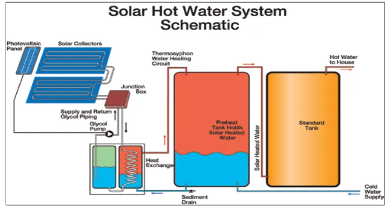
met even when there is insufficient sunshine. Solar water heaters perform three basic operations as shown in
Figure 1:
Collection: Solar radiation is “captured” by a solar collector;
Transfer: Circulating fluids transfer this energy to a storage tank; circulation can be natural (thermosiphon
systems) or forced, using a circulator (low-head pump); and
Storage: Hot water is stored until it is needed at a later time in a mechanical room, or on the roof in the case of
a thermosiphon system.
Fig.1:-System Schematic for Typical Solar Domestic Water Heater
III. SOLAR COLLECTORS
Solar energy (solar radiation) is collected by the solar collector’s absorber plates. Selective coatings are often
applied to the absorber plates to improve the overall collection efficiency.
A thermal fluid absorbs the energy collected. There are several types of solar collectors to heat liquids. Selection
of a solar collector type will depend on the temperature of the application being considered and the intended
season of use (or climate). The most common solar collector types are: unglazed liquid flatplate collectors;
glazed liquid flat-plate collectors; and evacuated tube solar collectors.
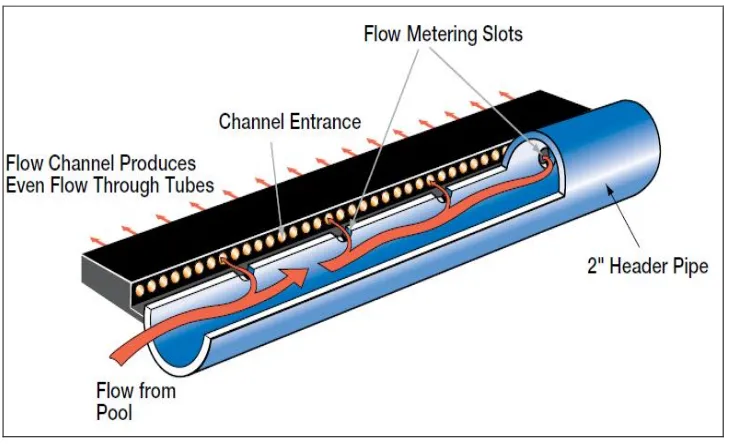
Unglazed liquid flat-plate collectors
Unglazed liquid flat-plate collectors, as depicted in Figure 2, are usually made of a black polymer. They do not
normally have a selective coating and do not include a frame and insulation at the back; they are usually simply
laid on a roof or on a wooden support.
These low-cost collectors are good at capturing the energy from the sun, but thermal losses to the environment
increase rapidly with water temperature particularly in windy locations. As a result, unglazed collectors are
commonly used for applications requiring energy delivery at low temperatures (pool heating, make-up water in
fish farms, process heating applications, etc.); in colder climates they are typically only operated in the summer
Fig.2-System Schematic for Unglazed Flat-Plate Solar Collector.
Glazed liquid flat-plate collectors
In glazed liquid flat-plate collectors, as depicted in Figure 3, a flat-plate absorber (which often has a selective
coating) is fixed in a frame between a single or double layer of glass and an insulation panel at the back. Much
of the sunlight (solar energy) is prevented from escaping due to the glazing (the “greenhouse effect”). These
collectors are commonly used in moderate temperature applications (e.g. domestic hot water, space heating,
year-round indoor pools and process heating applications).
Fig.3 :-System Schematic for Glazed Flat-Plate Solar Collector
Evacuated Tube Solar Collectorss
Evacuated tube solar collectors, as depicted in Figure 4, have an absorber with aselective coating enclosed in a
sealed glass vacuum tube. They are good at capturing the energy from the sun; their thermal losses to the
environment are extremely low.
Systems presently on the market use a sealed heat-pipe on each tube to extract heat from the absorber (a liquid is
vaporised while in contact with the heated absorber, heat is recovered at the top of the tube while the vapour
requiring energy delivery at moderate to high temperatures (domestic hot water, space heating and process
heating applications typically at 60°C to 80°C depending on outside temperature), particularly in cold climates.
Fig.4 :-System Schematic for Evacuated Tube Solar Collector
IV. EXPERIMENTAL SETUP
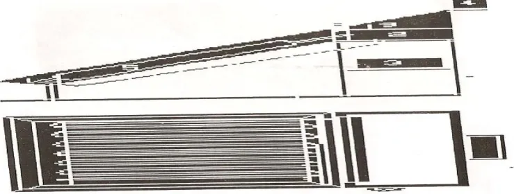
Experimental set up consists of two system, batch type flat plate collector and distillation unit. Figure 5 shows
the schematic diagram of the general layout and experimental setup.
When solar radiation fell on collector, water was heated and circulated in the system automatically by natural
convection (thermo-siphon). Above the hot water storage tank a water trough was provided for cooling glass
cover for distillation unit. Temperature difference between the hot water of the storage tank and the top cover
produced the convection current inside the storage tank. These current brought the humid air into the contact
with relatively cool cover and resulted in condensation of the humidity on the surface of cover. The condensed
droplets slid down on the slanting surface of cover and were collected in the distillation tank, and further drained
out of the enclosure through the
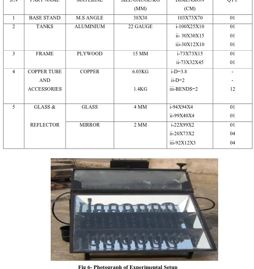
V. SPECIFICATION
S.N PART NAME MATERIAL SIZE/GAUGE/KG
(MM)
DIMENSION
(CM)
QTY
1 BASE STAND M.S ANGLE 38X38 103X73X70 01
2 TANKS ALUMINIUM 22 GAUGE i-100X25X10
ii- 30X30X15
iii-30X12X10
01
01
01
3 FRAME PLYWOOD 15 MM i-73X73X15
ii-73X32X45
01
01
4 COPPER TUBE
AND
ACCESSORIES
COPPER 6.03KG
1.4KG
i-D=3.8
ii-D=2
iii-BENDS=2
-
-
12
5 GLASS &
REFLECTOR
GLASS 4 MM i-94X94X4
ii-99X40X4
01
01
MIRROR 2 MM i-22X99X2
ii-20X73X2
iii-92X12X3
01
04
04
VI. EXPERIMENTAL OBSERVATIONS
With Trough Without Trough
Table 1- Experimental Result
VII. RESULTS AND DISCUSSION
The batch type solar water heater cum distillation device was tested in month of December and January, with
trough and without trough condition.
The results obtained during the course of test : SR.N
O
TIME ATM.T
EMP
(oC)
HOT WATER
TEMP. (oC)
1 9:00 28 27
2 9:30 28 29
3 10:00 29 32
4 10:30 29 35
5 11:00 30 40
6 11:30 30 42
7 12:00 30 45
8 12:30 32 47
9 1:00 32 48
10 1:30 33 50
11 2:00 33 51
12 2:30 34 52
13 3:00 34 52
14 3:30 33 51
15 4:00 33 51
16 4:30 33 50
17 5:00 30 48
18 5:30 30 47
19 6:00 29 46
20 6:30 28 45
21 7:00 27 44
22 7:30 27 44
23 8:00 26 43
24 8:30 25 43
25 9:00 25 42
S.N TIME ATM.T
EMP
(oC)
HOT WATER
TEMP
(oC)
1 9:00 26 25
2 9:30 27 28
3 10:00 28 29
4 10:30 29 32
5 11:00 29 35
6 11:30 30 40
7 12:00 30 42
8 12:30 30 45
9 1:00 32 47
10 1:30 32 48
11 2:00 33 50
12 2:30 33 51
13 3:00 33 52
14 3:30 34 52
15 4:00 35 52
16 4:30 34 52
17 5:00 33 50
18 5:30 30 48
19 6:00 30 47
20 6:30 29 46
21 7:00 28 45
22 7:30 27 44
23 8:00 26 43
24 8:30 25 43
Maximum temperature of water in storage tank was found 55C
With thermal efficiency 55%
And distillate output is 556ml/day.
With Trough condition, efficiency of distillation unit is improved around 28%
VIII. CONCLUSION
Based on experimental performance following conclusions can be drawn-
1. Generally, hot water is required during morning and water in insulated tank gets heated through out the day.
That heat is utilized in the distillation unit.
2. In many areas there is less availability of drinking water, for such areas the system is very useful.
3. The time required for the heating of water is less due the batch type arrangement with fins.
4. Large area available for heat transfers, hence high thermal performance.
5. Concentration of solar energy on absorber is more due to attachment of mirrors, hence no need of tracking
system.
6. Solar energy is available abundantly in our country, hence no running cost of unit.
7. There is no need of electricity for the purification & heating of water
8. The most important advantage of this system is that the water heating and distillation unit present in same
REFERENCES
[1]. Garg.H.P, Solar water heating system, Tata McGraw, New Delhi 2000.
[2]. Magal.B.S, Solar power engg, Tata McGraw, New Delhi 1999.
[3]. Rai.G.D, Non conventional energy sources, Khanna Publication, New Delhi 2000.
[4]. Tiwari.G.N, Recent advances in solar distillation, Tata McGraw, New Delhi 2001.