HARDWARE IMPLIMENTATION OF FPGA BASED
PID CONTROLLER
Amol patil
1, Prof. Suresh Jajoo
21,2
EXTC,DMCE, Airoli, Navi Mumbai (India)
ABSTRACT
In this paper, we focused our work on performance analysis and implementation of digital controller based on
Field Programmable Gate Array (FPGA) device .In proposed system implementation of software module using
‘VHDL’ for Xilinx FPGA (XC3S400) based PID controller for temperature control system is presented. FPGA
based system allows design up gradation in the field with no hardware replacement. FPGA is a superior
alternative to mask programmed ASICS. It also offers good closed-loop performance while using less resources,
resulting in cost reduction, high speed, and low power consumption, which is desirable in embedded control
applications.
Keywords: Field Programmable Gate Array (FPGA); Proportional-Integral-Derivative (PID)
controller ;Very High Speed Integrated Circuit Hardware Description Language (VHDL); Pulse
Width Modulation (PWM) ; Application Specific Integrated Circuits (ASICS).
I. INTRODUCTION
A plant and controller are two subsystems of control system. The plant is an entity controlled by the controller. The controller can be either analog or digital. The proportional–integral–derivative (PID) controller is one of the most common types of feedback controllers that are used in dynamic systems . This controller has been widely used in many different areas, such as temperature control, process control, manufacturing, robotics, automation, power electronics and transportation systems. Implementation of PID controllers has gone through several stages of evolution, from early pneumatic devices, followed by vacuum and solid state analog electronics before arriving at today’s digital implementation via microprocessors or FPGA [1].
Recently, Field Programmable Gate Arrays (FPGA) is becoming alternative solution for the realization of digital control systems. And the operations on FPGA are hardware compatible [4]. Building PID controllers on Field Programmable Gate Arrays (FPGAs) improves speed, accuracy, power efficiency, compactness and cost effectiveness. These are attractive features from the embedded systems design point of view. Previous work has reported the use of FPGAs in digital feedback control systems, such as magnetic bearings, pulse width modulation (PWM) inverters, induction motors , ac/dc converters , variable-speed drives , and anti windup compensation of controllers . Another advantage of FPGA-based platforms is their capability to execute concurrent operations, allowing parallel architectural design of digital controllers [1]. When design is implemented on FPGA they are designed in such a way that they can be easily modified if any need arise in future. We have to just change the inter connection between these logic blocks. This feature of reprogramming capability of FPGA makes it suitable to make your design using FPGA. Using FPGA within a short time, fast implementation of design can also possible. Also implementation of FPGA-based digital control schemes proves less costly and hence they are economically suitable for small designs. Thus FPGA is the best way of designing digital PID controller [3].
II. PID CONTROLLER
The PID algorithm consists of three modes proportional, integral and derivative mode. It has a simple control structure which was understood by plant operators which they found relatively easy to tune. Since many control systems using PID controller have proved its satisfactory performance, it still has a wide range of applications in industrial control and it has been an active research topic for many years [4].
Fig2.1Block Diagram of a General PID Based Feedback Control System.
The equation that describes the PID controller behavior in continuous time domain is
Kd derivative gain
Transfer function of PID controller, is by taking Laplace transform.
Integral time constant,
Derivative time constant,
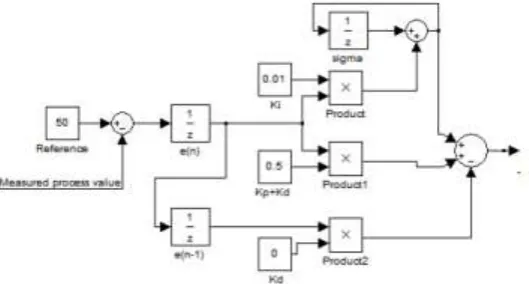
Now apply the backward difference method, Then,
From above equation and following [5] we can construct the algorithm’s block diagram shown in figure 2.
Fig 2.2: Digital PID Controller Algorithm
Fig2.3. Simulink Waveform for PID Controller for Set Point 50
control action is used. Derivative control is used to dampen out oscillations in the plant response. Also, the presence of derivative control reduces the need of Kp being large to achieve stability [6].
Fig2 .4 Application Based Block Diagram
III. PID CONTROLLER & PULSE WIDTH MODULATOR
The PID controller follows the classical structure. It contains two saturation Blocks, one for the integral part and the other for the overall sum (see figure 5). The controller has a pipeline structure of three stages, in other words, it needs three clock cycles to perform all the operations. In order to improve the area and speed, hardware multipliers have been used . These multipliers are included in the Spartan 3 family of Xilinx and subsequent FPGAs. These multipliers have 15 bit input data bus and are signed. This leads to optimum implementation when the fixed point implementation uses less than 15 bit in two’s complement [4].
Fig3.1. Block Diagram ff Robust PID Controller
The PWM modulator admits a two’s complement input and transforms it into a PWM signal. (see figure 6). The PWM module also generates the enable signal for the control loop. This signal makes the PID controller begin a new cycle and calculate a new PWM input value.
The basic principle is, a data register stores the value which is loaded on to the Up/Down counter. Whenever the counter reaches its terminal count. The terminal counter is used to generate the pulse width modulation. A data register is used to store the value for the counter. Value determines the width of the pulse . The Up/Down Counter loaded with a new value from the data register when the counter reaches its terminal count. Toggle Flip-flop generates the PWM output. When data value is first loaded, counter counts-down from data value to zero. Now terminal count and PWM signals are Low. When counter goes through 0 transition state, terminal count(TC ) is generated. Triggers Toggle Flip-flop to drive PWM signal High. Now Data value is re-loaded and counting proceeds up to maximum value.Again Terminal count(TC) is generated when counter reaches its maximum value. Drives PWM signal to toggle from High to Low. Data value is re-loaded and cycle repeats. Direction of counter is controlled by PWM signal. Counter is set to count down when PWM is Low, and count up when PWM is High. Terminal count signal controls data value loaded to counter from data register. Data is loaded when terminal count is High. Duty cycle of the PWM signal is controlled by data value.
IV. CONCLUSION
In proposed system, a FPGA-based design approach is applied to design a temperature control system. In general, embedded control designers need to go through three phases in the design of digital control systems: 1) software modeling/simulation in an environment such as Matlab/Simulink; 2) hardware implementation; and 3) cosimulation of the whole system including both hardware and software [12]. Using reusable and reconfigurable modules, the designer’s task in developing control applications can be greatly simplified by porting the design into a familiar environment, such as Matlab /Simulink. The step response of the plant can be observed with the scope block As a result, the development time for designing efficient embedded software is greatly reduced.
REFERENCES
[1] Yuen Fong Chan, M. Moallem , and Wei Wang, “Design and Implementation of Modular FPGA-Based PID Controllers,” IEEE TRANSACTIONS ON INDUSTRIAL ELECTRONICS, VOL. 54, NO. 4,pp 1898-1906, AUGUST 2007.
[2] Prof. Vikas Gupta, Dr Kavita Khare ,and Dr R. P. Singh,“Efficient FPGA Design and Implementation of Digital PID Controllers in Simulink®,”International Journal of Recent Trends in Engineering, Vol 2, No. 6, pp 147-150,November 2009.
[3] Vipul B. Patel, Virendra singh,and Ravi H.Acharya,
[4] “Design of FPGA-based All Digital PID Controller for Dynamic Systems,” International Journal of Advanced Research in Electrical, Electronics and Instrumentation Engineering ,Vol. 1, Issue 2, pp 64-72, August 2012.
[5] Ivneet Kaur Kaler and Ritesh Diwan, “ Study of FPGA based PID controllers,” International Journal of Advanced Research in Electronics and Communication Engineering (IJARECE), Volume 2, Issue 8, pp 708-712, August 2013.
[7] Nikunj A. Bhagat , Mahesh Bhaganagare ,and Prof.P.C.Pandey, “DC Motor Speed Control using PID Controllers,” EE 616 Electronic System Design Course Project, EE Dept, IIT Bombay, pp 1-18, November 2009.
[8] G. Eason, B. Noble, and I.N. Sneddon, “On certain integrals of Lipschitz-Hankel type involving products of Bessel functions,” Phil. Trans. Roy. Soc. London, vol. A247, pp. 529-551, April 1955. (references)
[9] J. Clerk Maxwell, A Treatise on Electricity and Magnetism, 3rd ed., vol. 2. Oxford: Clarendon, 1892, pp.68-73.
[10]I.S. Jcobs and C.P. Bean, “Fine particles, thin films and exchange anisotropy,” in Magnetism, vol. III, G.T. Rado and H. Suhl, Eds. New York: Academic, 1963, pp. 271-350.
[11]K. Elissa, “Title of paper if known,” unpublished.
[12]R. Nicole, “Title of paper with only first word capitalized,” J. Name Stand. Abbrev., in press.
[13]Y. Yorozu, M. Hirano, K. Oka, and Y. Tagawa, “Electron spectroscopy studies on magneto-optical media and plastic substrate interface,” IEEE Transl. J. Magn. Japan, vol. 2, pp. 740-741, August 1987 [Digests 9th Annual Conf. Magnetics Japan, p. 301, 1982].