https://doi.org/10.5194/se-9-683-2018
© Author(s) 2018. This work is distributed under the Creative Commons Attribution 4.0 License.
Permeability and seismic velocity anisotropy across a ductile–brittle
fault zone in crystalline rock
Quinn C. Wenning1, Claudio Madonna1, Antoine de Haller2, and Jean-Pierre Burg1 1Department of Earth Sciences, Institute of Geology, ETH Zurich, Zurich, Switzerland 2Department of Earth Sciences, University of Geneva, Geneva, Switzerland
Correspondence:Quinn C. Wenning (quinn.wenning@erdw.ethz.ch) Received: 2 March 2018 – Discussion started: 5 March 2018
Revised: 30 April 2018 – Accepted: 8 May 2018 – Published: 29 May 2018
Abstract.This study characterizes the elastic and fluid flow properties systematically across a ductile–brittle fault zone in crystalline rock at the Grimsel Test Site underground re-search laboratory. Anisotropic seismic velocities and perme-ability measured every 0.1 m in the 0.7 m across the tran-sition zone from the host Grimsel granodiorite to the my-lonitic core show that foliation-parallel P- and S-wave veloc-ities systematically increase from the host rock towards the mylonitic core, while permeability is reduced nearest to the mylonitic core. The results suggest that although brittle de-formation has persisted in the recent evolution, antecedent ductile fabric continues to control the matrix elastic and fluid flow properties outside the mylonitic core. The juxtaposition of the ductile strain zone next to the brittle zone, which is bounded inside the two mylonitic cores, causes a significant elastic, mechanical, and fluid flow heterogeneity, which has important implications for crustal deformation and fluid flow and for the exploitation and use of geothermal energy and geologic waste storage. The results illustrate how physical characteristics of faults in crystalline rocks change in fault zones during the ductile to brittle transitions.
1 Introduction
Brittle faults and ductile shear zones and their associated damage and high-strain zones have a localized yet influen-tial impact on crustal mechanics and fluid flow (see reviews by Sibson, 1994; Faulkner et al., 2010). Physical properties in and around the fault core and damage zone in the brit-tle regime generally differ from the host rock by several
or-ders of magnitude, asserting tremendous influence on fluid flow, deformation, earthquake rupture, and the development of economically exploitable resources. Less is known about the nature of the physical properties of ductile shear zones, and their role in crustal mechanics and fluid flow distribution once they are exhumed (e.g., Bolognesi and Bistacchi, 2016; Donath, 1961). Thus, understanding the nature of the geo-metrical distribution and temporal evolution of the properties associated with ductile shear zones and their transition into brittle faults and damage zones is integral to assess crustal mechanics and fluid flow distribution.
permeabil-ity due to microfracturing occurs regardless of the tectonic faulting regime (Faulkner and Armitage, 2013).
In the ductile deformation regime, shear zones are under-stood to develop anisotropic properties due to mineral align-ment of anisotropic minerals in preferred elongation direc-tions (shape-preferred orientation or SPO) and/or alignment of the crystallographic axis (crystallographic preferred ori-entation or CPO) of minerals (Mainprice, 2007). The char-acteristics of ductile shear zones have been studied in terms of their anisotropic velocity structure to assess observations in middle to lower crustal seismic reflectivity (see review by Almqvist and Mainprice, 2017). Rey et al. (1994) suggested that the physical properties in ductile shear zones should also be considered as transitional (i.e., the seismic velocities would grade into the ductile shear zone core). The strength of ductile shear zones is typically studied in terms of viscous rheology (e.g., Sibson, 1983). However, these shear zones are often “frozen in” and preserve their textural features that when exhumed behave with elastic and frictional failure cri-teria in the upper crust. In preserved ductile shear zones, me-chanical and fluid flow properties have typically been stud-ied separately. Géraud et al. (1995) studstud-ied the porosity and mineral structure across a mylonitic shear zone. Using em-pirical relationships between porosity and pore throat diam-eter, these authors were able to discern that the permeabil-ity decreases in the highest strained sample. Violay et al. (2017) performed triaxial deformation experiments across the brittle–ductile transition in Westerly granite and show that porosity changes in the ductile regime is compactant, while the brittle regime is marked by dilation.
The models for elasticity and permeability through brittle and ductile shear zones have been mostly derived from out-crop examples (Faulkner et al., 2010, and references therein). To date, there have been limited systematic mechanical and fluid flow studies on boreholes that directly penetrate fossil ductile shear zones. Drilling into fractured crystalline rock for geothermal exploitation has been ongoing since the 1970s (Vidal and Genter, 2018). Recent drilling through the Alpine Fault in New Zealand revealed how ductile mylonites have been exhumed, altering the rocks to a typical brittle fault damage zone in the vicinity to the fault (Allen et al., 2017). Although much precaution is taken in outcrop studies, core material provides the opportunity to sample systematically into a fault zone eliminating issues of surface weathering and processes that may alter physical properties. However, precaution should be taken when assessing the extent and timing of hydrothermal alteration associated with faults at depth. Additionally, focus on the relationship between elas-ticity, mechanical strength, and permeability in the transition zone and core of faults has been inherently focused on brittle structures. However, with the importance of meeting sustain-able energy demands via geothermal energy and promoting safe geological waste disposal, the impact of preserved duc-tile structures in granitic rocks on mechanics and fluid flow
are also if increasing significance.(Violay et al., 2017; Watan-abe et al., 2017).
Recent drilling at the Grimsel Test Site (GTS), an un-derground research laboratory owned and operated by NA-GRA (National Cooperative for the Disposal of Radioactive Waste) located in central Switzerland, penetrated a ∼5 m thick ductile–brittle fault damage zone relict in the Grim-sel granodiorite host rock (Amann et al., 2018). Alpine tec-tonism produced multiple stages of ductile and subsequently brittle deformation in the Grimsel granodiorite, a member of the Aar massif (e.g., Rolland et al., 2009; Belgrano et al., 2016; Wehrens et al., 2016, 2017). The relict shear zone penetrated by the borehole is bounded by two foliated duc-tile shear zones, which initially localized ducduc-tile deforma-tion and further reactivated brittlely between the two foliated shear zones. This study concentrates on characterizing the elastic and fluid flow properties from the surrounding gran-odiorite rock mass through the ductile transition zone into the bounding foliated shear zone. Seismic P- and S-wave veloc-ities (VpandVs) and gas permeability (k) were measured on core samples in the laboratory. This paper emphasizes that the mineralogical changes entering the shear zone influence changes in physical properties near the ductile–brittle dam-age zone. The results also provide insight on the transient behavior of faults during the transition from ductile to brittle regimes through exhumation processes and provide insight on their effect on economic exploitation of such shear zones in terms of geothermal energy or geological waste disposal.
2 Geologic setting and core details
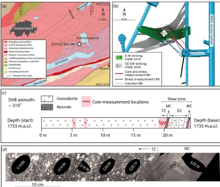
The GTS is located in the Aar Massif in central Switzerland (Fig. 1a). The underground laboratory is situated in Grimsel granodiorite in the Haslital. Schaltegger and Corfu (1992) place the age of the Grimsel granodiorite at 299±2 Ma. From field relations and dating, the Grimsel granodiorite has the same age as the Central Aar granite. These intrusions postdate Variscan collision, and there are no identified pre-Alpine deformation structures.
Figure 1. (a)Geologic map of the Grimsel pass region (after Wehrens et al., 2016, 2017);(b)borehole orientations (this study – red borehole) with respect to the underground research laboratory (after Krietsch et al., 2017; Amann et al., 2018);(c)the borehole in this study depicting the location of the damage zone with coring and stress measurement locations projected along the borehole. The shear zone at the base is divided into three components: (1) transition zone (TZ), (2) mylonitic core (MC), and (3) damage zone (DZ).(d)Photograph of a saw-cut cross section through part of the transition zone and the mylonitic core (black ellipses show subcored cylinders inclined to the cut surface).
and subsequent embrittlement of these shear zones, which has produced fault breccias, cataclasites, and fault gouge.
The Aar granites experienced 300–450◦C and 150 to 250 MPa peak conditions during Alpine metamorphism (Steck, 1968; Rolland et al., 2009; Wehrens et al., 2016, 2017). Our thin section observation shows fracturing of feldspar and undulose extinction along with subgrain bound-aries in quartz, which are consistent with the inferred meta-morphic temperatures.
In 2015, a series of boreholes were drilled in the Grimsel granodiorite (Fig. 1b) for stress measurements, petrophysical property characterization, and hydraulic stimulation of the shear zones (Amann et al., 2018). The core material used in this study comes from the borehole drilled from an offset of the main tunnel in the GTS that penetrates two parallel shear zones. The well was drilled from 480 m below the ground
surface in a subhorizontal trajectory with an azimuth of 319◦. The well penetrates ∼20 m of mostly non-fractured gran-odiorite (Fig. 1c). The grangran-odiorite is foliated and at 20.2 m intersects a 20 cm thick foliated mylonitic shear zone, also defined as a foliated mylonitic core (MC). The foliation in-tensity in the granodiorite decreases towards the host rock
1 mm aperture quartz-filled fractures intersect the MCs orig-inating from within the damage zone. However, these do not appear to penetrate entirely through the MCs.
3 Methods
3.1 Sample selection, preparation, and characterization
In order to determine the spatial relationship of the physi-cal properties in the shear zone a continuous set of samples was cored every 0.1 m in the transition zone from 19.6 m to the border of the first MC at 20.1 m. Abundant fractures in the damage zone between the two MCs prevented continu-ous coring. Two mutually perpendicular core samples, one parallel (x1) and one perpendicular (x3) to the Grimsel gra-nodiorite foliation were taken to characterize the physical property and anisotropy changes as a gradient away from the mylonitic core. Sampling farther than 19.5 m was not possible due to previously made overcoring stress measure-ments (Fig. 1c). In order to optimize the number of sam-ples, thex1direction was taken∼15◦off axis from the lin-eation (Fig. 1d). Foliation perpendicular samples could not be taken at 19.5 and 20.1 m because of breaks in the core. The x1 andx3 samples were bored out of the core using a diamond drill bit (2.54 cm inner diameter) with water as the cooling fluid. The 2.49 to 5.56 cm long samples were ground and polished to craft parallel ends. To characterize the MC, parallel and perpendicular to foliation samples were taken at 20.2 and 23.6 m, respectively. There is a maximum length (∼2.49 cm) to diameter (∼2.53 cm) ratio of approximately 1:1 in the MC samples, due to the extremely fissile nature of these rocks. Additionally, these two samples come from separate but similar MC at the base of the borehole due to limited sample material. Since the seismic velocity measure-ments require longer samples due to signal noise and wave propagation issues, the MC samples are only long enough to perform only permeability measurements. Additionally, two sets of perpendicular samples were taken 5 and 7 m from the start of the borehole as a background Grimsel granodiorite reference.
Thin sections were prepared directly from the ends of the samples and observed under optical microscopy. Quantitative mineral analysis was obtained at the University of Geneva us-ing QEMSCAN®Quanta 650F, an automated scanning elec-tron microscope with mineral identification based on a com-bination of back-scattered electron values, energy-dispersive X-ray spectra, and X-ray count rates. High-resolution min-eralogical and petrographic maps were obtained with the QEMSCAN®at a scanning resolution of 5 µm, which mea-sures the mineral coverage in percent area.
3.2 Density, porosity, and permeability measurements Measurements of matrix volume and mass were performed after the samples were dried in an oven at 100◦C for 24 h for the granodiorite samples and 40◦C for the fragile MC samples. The matrix volume was measured using a helium pycnometer (AccuPyc 1330, Micromeritics®). The dry mass was measured with a precision balance. The bulk rock den-sityρbulkwas calculated as the dry mass divided by the ma-trix volume of the sample. The porosity (φ) of each cylin-drical sample was calculated from the geometrical volume (Vtot) and the matrix volume (Vm) from the helium pycnome-terφ=(Vtot−Vm)/Vtot.
A hydrostatic pressure vessel was used to measure the gas permeability of each sample (detailed description of the apparatus and measurement technique in Pini et al., 2009). The hydrostatic pressure vessel is equipped to measure sam-ples of 2.5 cm in diameter and up to ∼5 cm in length at confining pressures up to 20 MPa. Hydraulic oil is used as the confining fluid, which is controlled with a screw-type displacement pump that regulates the confining pres-sure within±0.05 MPa. The sample assembly consists of the cylindrical rock specimen placed between two stainless steel disks fastened by a soft PVC tube to isolate the sample from the confining fluid. The two stainless steel disks have inter-connected circular grooves to distribute the fluid across the cross-sectional area of the sample. The disks are connected via a plumbing system to the upstream and downstream reservoirs, which can be isolated and filled with the injected gas. The upstream and downstream reservoir, plus their as-sociated plumbing network, have volumes of 50.8 cm3 and 21.2 cm3, respectively. The gas pressure in the two reservoirs is measured within 0.05 %.
Due to the low porosity and permeability in the granodi-oirite and MC, the transient step technique was used to per-form and analyze the flow experiments (Brace et al., 1968). Experiments were performed at room temperature and an ef-fective pressure of 10 MPa, chosen to represent the efef-fective stress conditions in the GTS. Three confining pressure and pore pressure configurations that preserved an effective pres-sure of 10 MPa were performed to assess the Klinkenberg gas slippage effect (Klinkenberg, 1941). For each sample a pressure difference of 0.5 MPa was imposed between the up-stream (Pus) and downstream (Pds) reservoir and allowed to equilibrate at each of the pore pressure configurations (e.g., PusandPds= 1.0 and 0.5 MPa, 3.0 and 2.5 MPa, and 7.0 and 6.5 MPa, respectively). In some cases, the sample permeabil-ity was so low that reaching a full equilibrium between the up- and downstream reservoir was not possible within labora-tory timescale. For these samples, only the beginning part of the partial pressure gradient equilibration has been assessed (correlating to a pressure drop of<0.1 MPa).
and time to estimate permeability. Dicker and Smits (1988) developed a simple analytical expression to estimate perme-ability from the measured pressure curves. The simple ana-lytical solution
k= βµφL
2s
f (Vsa/Vus, Vsa/Vds)
(1) is a function of the compressibility, β, and viscosity, µ, porosity, φ, length of the sample, L, slope of the differen-tial pressure vs. time,s, and a function of the ratio between the volume of the sample (Vsa) and the volume of the up-and downstream reservoirs (Vus andVds, respectively). The solution is accurate within 0.3 % of the full expression if the pore volume is less than the reservoir volumes, which is true for our experiments. Since the pressure difference in the two reservoirs is small, we used an average pore pressure to deter-mine the compressibility and viscosity of the argon gas using the NIST database (NIST, 2017).
3.3 Elastic wave velocity measurements and calculations
A separate hydrostatic oil-medium pressure vessel, capable of reaching high confining pressures, was used to measure the P- and S-ultrasonic elastic wave velocities using the pulse transmission technique (Birch, 1960). The measurements were conducted on the mutually perpendicular samples up to 260 MPa and at room temperature conditions (detailed description of the measurements found in Zappone et al., 2000). The mechanical impulse is directed into the sample by mounting the lead zirconate titanate piezoceramic trans-ducer inside a “head” assembly that also contains a buffer rod, reducing the dispersion of energy. The setup is config-ured so that one transducer transforms the electrical impulse (1 MHz resonance frequency) and emits a mechanical wave at the coupling of the transducer with the sample. After pass-ing through the sample, another transducer converts the me-chanical wave back into an electrical signal. The electronic system consists of a Hewlett Packard®214B Pulse Genera-tor that is connected to the transducers with coaxial cables and the output is recorded directly with a computer. To pre-vent oil seepage from the confining fluid into the sample, a thin polyolefin heat shrink tube is fitted over the ends of the transducers and the sample.
The velocity in the rock is given by Vp,s=
L tsample
withtsample=ttotal−tsystem, (2)
where the P- and S-wave velocities,Vp,s, are a function of the travel time through the sample,tsample, and its length,L. The travel time through the sample is determined by subtracting the travel time of the cabling in the source–receiver system, tsystem, from the total time of flight of the impulses recorded, ttotal.
The waveforms are recorded at stepwise increases or de-creases in pressure in the loading and unloading cycles performed for each P- and S-wave experiment. Measure-ments were recorded across the full pressure range of 30 to 260 MPa of the apparatus to investigate the properties closest to present-day low-pressure conditions at the GTS (minimum principal stress 8 to 12 MPa, maximum principal stress 13– 17 MPa Krietsch et al., 2017) and to study the poro-elastic effect on seismic velocities after crack closure at high pres-sure (Birch, 1960). The meapres-surements were made at room temperature and in dry, undrained conditions. Recordings of the waveform were measured within ±2 MPa and a travel time accuracy of±0.01 µs.
Velocity anisotropy (AV) was estimated from the maxi-mum, minimaxi-mum, and mean velocities using
AVp,s=
Vp,s max−Vp,s min Vp,s mean
·100. (3)
Estimates of the dynamic elastic moduli were also calculated for each experiment. The P- and S-wave moduli are repre-sented in the general form ascxx=ρVp2,s. The P-wave mod-uli for the vertical (x3) and maximum horizontal (x1) sam-ples are represented byc33 andc11, respectively. Similarly, the S-wave moduli, also known as shear modulus (µ), for the vertical and maximum horizontal samples are represented by c44andc66, respectively. The elastic moduli are estimated by applying the isotropic equations to the vertical and horizontal components separately in order to estimate the P- and S-wave moduli (Mavko et al., 2009). Sone and Zoback (2013) show that the error in applying the isotropic equations to the ver-tical and horizontal components separately in the absence of having the 45◦-oriented sample is negligible. The dynamic Young’s moduli are approximated for the parallel (E1) and perpendicular (E3) components using the following equa-tions:
E1=
c66(3c11−4c66) c11−c66
, (4)
E3=
c44(3c33−4c44) c33−c44
. (5)
The dynamic Poisson’s ratio for the parallel (ν1) and perpen-dicular (ν3) sample is calculated using the isotropic equation
ν=1
2
(Vp/Vs)2−2 [(Vp/Vs)2−1]
. (6)
The dynamic bulk modulus for the parallel (K1) and per-pendicular (K3) sample is calculated using the isotropic equation
K=ρ(Vp2−4
3V 2
4 Results
4.1 Characterization
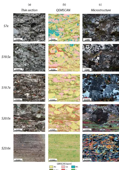
In general there is a decrease in grain size in the TZ to-ward the MC (Fig. 1d; data available in Wenning et al., 2018). Additionally, millimeter-thick shear bands become more frequent nearer to the MC until reaching the sharp boundary with the MC. The MC itself is heterogeneously layered and folded. The compositional and microstructural transition from the “host” granodiorite, through the transition zone (TZ), and the mylonitic core (MC) are depicted in Fig. 2 and the rock composition is summarized in Table 1. The den-sity of granodiorite samples irrespective of their proximity to the MC varies between 2.72 and 2.78 g cm−3with porosity varying between 0.4 to 1 % (Table 1). In general, the sam-ples do not have visible open microcracks; thus, the poros-ity occurs between grain contacts (i.e., intergranular microp-ores). The density of the MC from both sampling locations is 2.80 and 2.84 g cm−3and porosity estimates are 0 and 1 %, respectively.
The samples (S5 to S20.1) from the granodiorite are made up of various amounts of plagioclase (albite), quartz, K-feldspar, biotite/phlogopite, muscovite, and epidote. The amount of each mineral phase and microstructure depends on the vicinity to the mylonitic core. In the samples taken from the host granodiorite (S5 and S7) as well as samples farthest from the mylonitic core (S19.5 and S19.6) the microstruc-ture and composition is similar. Plagioclase is the most abun-dant mineral phase (∼40 %). The sub-millimeter to > 10 mm big plagioclase grains are rounded to subangular. The grain size of plagioclase varies from sub-millimeter to > 10 mm. Needle-like sericite inclusions (< 0.1 mm) form within the plagioclase cleavage planes, indicating that hydrothermal al-teration occurred. Quartz subgrains also develop along the boundaries and within large plagioclase grains. In larger pla-gioclase grains brittle fractures are filled with biotite and quartz. Quartz is the second-most abundant mineral phase (∼17 to 25 %). Quartz grains of variable size (< 1–2 mm) typically occur as many rounded to subhedral individual sub-grains that form lenses or develop in the strain shadows of plagioclase clasts (Fig. 2). The main difference between the host granodiorite (S5 and S7) and the beginning of the tran-sition zone (S19.5 and S19.6) is the K-feldspar concentra-tion, which is ∼15 to 17 % and ∼5 %, respectively. Phyl-losilicates in the form of biotite and muscovite form anasta-mosing lenses of mixed muscovite and biotite with variable thickness across the thin section, which comprise about 15 to 18 % of the total mineralogy. Biotite forms < 0.1 to 1 mm grains, of which the individual grains are randomly oriented in the anastamosing lenses.
A progressive change in the overall microstructure, state of the individual minerals, and the mineral composition is observed in the transition zone between samples S19.7 and S20.1. In Sample S19.7 the foliation becomes more
contin-uous across the thin section when compared to the host gra-nodiorite samples. Plagioclase deforms brittlely in the form of fracturing (Fig. 2), while grain boundary migration, un-dulose extinction, and subgrain rotation is observed in the quartz grains indicates ductility. Plagioclase and quartz grain size are similar to host granodiorite. Lenses of biotite and muscovite extend across the thin section more continuously; however, the lenses form variable thicknesses that wrap around the intermixed plagioclase and quartz. The anasto-mosing lenses are still present. In the samples nearest the MC (S20.0 and S20.1), the continuity and thickness of the mica-rich layers across the sample are the most developed. The foliation planes are oriented towards the parallel alignment of the individual grains. Biotite and muscovite grains are es-pecially larger in samples S20.0 and S20.1, where individ-ual grains can be >5 mm long. While lenses of fine-grained phyllosilicates occur, the overall grain size, continuity, layer thickness, and orientation of the individual grains is greater and more continuous. The total phyllosilicate amount in-creases from∼15 to 18 % in samples S5 to S19.6 to∼30 % in samples S20.0 and S20.1, with the other tectosilicates (pla-gioclase, K-feldspar, and quartz) reducing as a result. Biotite and quartz appear in the strain shadows of the plagioclase clasts (Fig. 2).
The MC sample (S23.6) is constituted of very fine-grained ultramylonitic (more than 90 % grain size reduction) pla-gioclase (31 %), biotite (27 %), quartz (22 %), and epidote (12 %) making up the main mineral constituents. The foli-ation is defined by the biotite-quartz/plagioclase preferred shape orientation (layers typically < 0.1 mm). Recrystallized plagioclase and quartz form rotated clasts within the biotite-quartz foliation. The shear zones in the region are often in-terpreted as former mafic dykes (e.g., Wehrens et al., 2017). The MC has a gradient of deformation between the Grimsel granodiorite in the TZ and the MC, and most notably there is a heterogeneous layering within the ultramylonite with larger grain lenses that are compositionally similar to the granodi-orite (e.g., Fig. 1d). We interpret this structure more broadly as a mylonitic shear zone with a strain gradient of decreasing deformation away from the mylonitic cores.
4.2 Velocity measurements and elastic moduli calculation
Seismic velocities (Fig. 3 and Table 2; data available in Wen-ning et al., 2018) are reported for the 30 MPa confiWen-ning pres-sure meapres-surement (i.e., the closest meapres-surement to the stress magnitudes in the GTS). The measured velocities parallel to foliation at 30 MPa, (Fig. 3 and Table 2) show an increase across the∼0.5 m transition zone. In the two samples taken from the host granodiorite (S5 and S7) P-wave velocity par-allel to the foliation (Vpx1) are∼5.5 km s
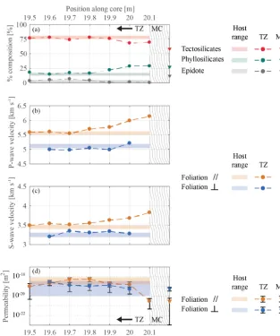
Figure 3.Sample composition, seismic velocity, and permeability across the transition zone into the mylonitic core. Depth corresponds to sample name in Table 2.(a)Tectosilicates – quartz, plagioclase, and K-feldspar (red); phyllosilicates – biotite and muscovite (green); and epidote (grey).(b, c)P- and S-wave velocity parallel to foliation (orange) and perpendicular to foliation (blue). Measured at 30 MPa hydrostatic confining pressure.(d)Permeability parallel to foliation (orange) and perpendicular (blue). Permeability is reported as the median value measured for each sample, and the bars show the range of values in terms of minimum and maximum. Measured at 10 MPa effective pressure. For all panels the shaded region depicts the range of values from the host granodiorite samples (S5 and S7), the circular markers show the values measured through the transition zone (TZ), and the triangular markers show the values measured in the mylonitic core (MC). Error bars are depicted where the error is larger than the marker size.
core theVpx1 increases steadily and reaches a maximum in sample S20.1 (6.14 km s−1) directly adjacent to the MC at 20.2 m. The S-wave velocity follows a similar trend where the host samples and the samples farthest from the mylonitic core have a Vsx1 of ∼3.42 to 3.54 km s
−1 and the veloci-ties increase steadily and reach a maximum nearest the MC (S20.1: Vsx1=3.83 km s
−1). The velocities measured per-pendicular to the foliation,Vpx3andVsx3, fluctuate without a consistent trend between 4.98 and 5.21 km s−1and 3.20 and 3.35 km s−1, respectively. The P- and S-wave anisotropy is generally lower away from and higher near the MC. How-ever, there are outliers (e.g., S19.6), which can be attributed to bias from either a slowerx3velocity or a fasterx1velocity.
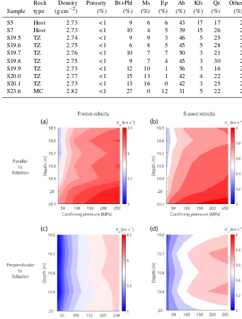
Table 1.Summary of sample composition: sample name refers to depth in the borehole; rock type refers to either the host granodiorite, transition zone (TZ), or mylonitic core (MC); dry bulk density and porosity are reported as an average of individual measurements for each sample (x1andx3); and mineral composition is derived from the QEMSCAN analysis of thex1-thin section in % area. Mineral abbreviations: Bt – biotite; Phl – phlogopite; Ms – muscovite; Ep – epidote; Ab – albite; Kfs – K-feldspar; and Qz – quartz.
Rock Density Porosity Bt+Phl Ms Ep Ab Kfs Qz Other
Sample type (g cm−2) (%) (%) (%) (%) (%) (%) (%) (%)
S5 Host 2.73 < 1 9 6 6 43 17 17 2
S7 Host 2.73 < 1 10 4 5 39 15 26 2
S19.5 TZ 2.74 < 1 9 9 3 46 5 25 2
S19.6 TZ 2.75 < 1 6 8 5 45 5 28 2
S19.7 TZ 2.76 < 1 10 7 7 50 3 21 2
S19.8 TZ 2.75 < 1 9 7 4 45 3 30 2
S19.9 TZ 2.73 < 1 12 10 1 56 3 16 2
S20.0 TZ 2.77 < 1 15 13 1 42 4 22 2
S20.1 TZ 2.73 < 1 13 16 0 42 3 25 2
S23.6 MC 2.82 < 1 27 0 12 31 5 22 2
Figure 4. (a)and(b)display the results for foliation parallel velocities (x1) separated intoVp(a)andVs(b).(c)and(d)display the results for foliation perpendicular velocities (x3) separated intoVp(c)andVs(d). ForVpandVsred colors indicate faster velocities and blue colors depict slower velocities (magnitude defined on the color bar).
Additionally, seismic velocities were measured up to con-fining pressures of 260 MPa in order to determine the intrin-sic crack-free velocities of the rocks (Fig. 4). BothVpandVs velocity contours show that for a given confining pressure, the velocities parallel to foliation tend to increase to
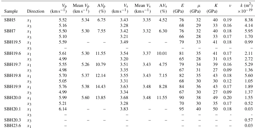
Table 2.Summary of density, porosity, elastic properties and anisotropy, and permeability obtained from laboratory measurements. Labora-tory velocities measured at 30 MPa confining pressure and permeability measured at 10 MPa effective pressure.
Vp MeanVp AVp Vs MeanVs AVs E µ K ν k(m2)
Sample Direction (km s−1) (km s−1) (%) (km s−1) (km s−1) (%) (GPa) (GPa) (GPa) ×10−19
SBH5 x1 5.52 5.34 6.75 3.43 3.35 4.52 76 32 40 0.19 8.38
x3 5.16 3.28 68 29 33 0.16 4.14
SBH7 x1 5.50 5.30 7.55 3.42 3.32 6.30 76 32 40 0.18 5.95
x3 5.10 3.21 66 28 33 0.17 1.70
SBH19.5 x1 5.59 – – 3.49 – – 79 33 41 0.18 0.99
x3 – – – – – – –
SBH19.6 x1 5.61 5.30 11.55 3.54 3.37 10.01 81 35 41 0.17 2.11
x3 4.99 3.20 65 28 31 0.15 2.72
SBH19.7 x1 5.55 5.26 10.79 3.51 3.43 4.75 79 34 39 0.16 5.29
x3 4.98 3.35 67 31 27 0.09 1.36
SBH19.8 x1 5.70 5.37 12.14 3.55 3.43 7.15 82 35 43 0.18 5.60
x3 5.05 3.31 68 30 30 0.12 1.05
SBH19.9 x1 5.76 5.38 14.43 3.63 3.48 8.28 84 36 43 0.17 1.89
x3 4.99 3.34 67 30 27 0.09 1.37
SBH20.0 x1 5.99 5.60 13.85 3.68 3.48 11.55 90 38 49 0.20 1.55
x3 5.21 3.28 70 30 35 0.17 0.52
SBH20.1 x1 6.14 – – 3.83 – – 95 40 50 0.18 0.03
x3 – – – – – -
-SBH20.3 x3 – – – – – – – – – – 0.57
SBH23.6 x1 – – – – – – 0.03
4.3 Permeability measurements
Permeability decreases (Fig. 3 and Table 2) from the host granodiorite and farthest samples in the transition zone (0.99 to 8.38×10⁻¹⁹m2) towards the samples nearest the my-lonitic core (0.03 to 1.89×10⁻¹⁹m2) along the x1 direc-tion (data available in Wenning et al., 2018). The permeabil-ity perpendicular to the foliation x3 fluctuates from 0.52 to 4.14×10⁻¹⁹m2. Permeabilities of similar host Grimsel gra-nodiorite at 5 MPa are 10−18to 10−20m2(David and Wasser-mann, 2017) and measurements on Kola granodiorite sam-ples range from approximately 10−18 to 10−20m2 at effec-tive pressures of 10 to 50 MPa (Morrow et al., 1994). Di-rectional permeability of the mylonitic core was measured on two samples from separate foliated shear zones due to difficulties in sample preparation (i.e., x3 is from 20.3 m depth and x1 is from 23.6 m depth). The permeability is 0.03×10⁻¹⁹m2 parallel to foliation and 0.57×10⁻¹⁹m2 perpendicular to the foliation. Flow along the boundary of a quartz-filled vein that crosscuts the perpendicular sample is believed to cause the increase in permeability perpendicular to foliation in the mylonitic core.
5 Discussion
5.1 Shear zone characterization
Many studies on the transition of elastic and fluid flow prop-erties in and around fault cores and damage zones have been
concentrated on outcrop material of brittle faults (Faulkner et al., 2010). Caine et al. (1996) present models for fault core geometries, with fault cores composed of fault gouge or cataclasite. Faulkner et al. (2010) expand this model to in-clude both single-fault core damage zones and damage zones made up of several anastamosing faults. Laboratory measure-ments on samples from natural fault systems have led to the development of brittle fault permeability and elastic or me-chanical properties that are microfracture dependent. In such systems, damage is concentrated in the fault core, which pro-duces fault gouge or cataclasite that can either be higher or lower in permeability than the surrounding host rock. In the host rock directly contacting the fault zone, microfracturing due to strain displacement around the fault leads to increased permeability and decreased elastic or mechanical strength (Faulkner et al., 2006). Permeability decreases and elastic or mechanical strength increases moving away from the dam-age zone core, as the microfracture intensity decreases away from the shear zone (e.g., Vermilye and Scholz, 1998; Wilson et al., 2003; Mitchell and Faulkner, 2009).
perme-ability across a mylonitic ductile shear zone was estimated from relationships between porosity and pore throat radius (Géraud et al., 1995). They show that permeability is reduced in the central shear zone core but is higher in the surround-ing strain gradient, which is higher than the host rock. Vio-lay et al. (2017) performed triaxial deformation experiments in Westerly granite across the brittle–ductile transition with simultaneous measurements of porosity. The authors found that the deformation in the ductile regime is associated with compaction, while the brittle regime is primarily dilatant. For shear zones that have undergone the transition from ductile to brittle deformation, a competing process between microfrac-ture and mineral-orientation-controlled physical properties can be envisaged.
The shear zone selected for measurements of seismic ve-locities and permeability in this study preserves both ductile and overprinting brittle structures. The shear zone penetrated by the borehole at GTS is characterized by foliation aligned with the mylonitic core that developed under viscous-flow deformation conditions (Wehrens et al., 2016). The foliation intensity is highest nearest the mylonitic core and decreases into the host granodiorite. The brittle fractures, which are bounded between the mylonitic cores, formed during a later brittle overprint. Figure 3 shows that the elastic and perme-ability transition into the mylonitic core is dissimilar to mod-els derived from brittle fault zones (e.g., Caine et al., 1996; Faulkner et al., 2010), even though brittle deformation is evi-dent in the damage zone. The measurements from GTS show a trend of increasing velocities and stable to decreasing per-meability in the plane parallel to foliation in the transition zone. In the direction perpendicular to foliation, the veloci-ties and permeability have minor fluctuation in the vicinity of the mylonitic core. The ductile strain gradient in the transi-tion zone does not appear to be influenced by the later stages of brittle deformation, as indicated by the increased seismic velocities and slightly decreasing permeability parallel to fo-liation towards the core in the transition zone. Should there be a brittle overprint, velocities would be expected to de-crease due to microfracturing; however, this is not the case (Birch, 1961; Siegesmund et al., 1991).
Instead, within the transition zone the both elastic and fluid flow properties are controlled by mineralogical changes in the rocks. Microfractures in thin section are scarce; thus, most of the <1 % porosity are intergranular micropores. It is important to note that these changes are localized within
∼1 m of the ductile mylonitic core. Since the material is bored from an underground research lab, alteration processes and weathering should be suppressed in such samples. The mineralogy of the samples shows a gradual change in com-position, losing tectosilicates (Pl, Fsp, and Qz) and gain-ing phyllosilicates (Bt and Ms), through the transition zone (Fig. 3). There is an increase in foliation intensity towards the mylonitic core. The faster foliation-parallel velocities are controlled by the alignment of the platy phyllosilicate miner-als (Lloyd et al., 2011a, b). Higher foliation-parallel
perme-ability compared to flow perpendicular, as measured in the GTS samples, has been measured in previous studies (e.g., Faulkner and Rutter, 1998; Leclère et al., 2015; Wibberley and Shimamoto, 2003; Uehara and Shimamoto, 2004). In low grade to ductile deformation, changes in the mineralogy and foliation structure alter the connection of intergranular micropores of the platy phyllosilicate and tectosilicate min-erals (e.g., Faulkner and Rutter, 1998; Leclère et al., 2015; Géraud et al., 1995). In this study the changes in mineral-ogy, most notably the phyllosilicate-to-tectosilicate ratio, is a driver in both the velocity and permeability anisotropy, where microcracks do not have a driving role due to their scarcity.
Outside the MCs, fractures along the borehole wall are un-common, as indicated by optical televiewer images (Krietsch et al., 2017). Between the MCs the density of fractures is high enough to have been termed damage zone. Although some fractures penetrate the MCs, they are typically quartz-filled and generally do not connect the granodiorite on ei-ther side of the mylonitic core. In the damage zone itself, fluid flow properties and elasticity are governed by the micro and macroscopic fractures. In the damage zone the velocities are decreased and the permeability increases, indicated by logging and pump tests in the borehole (Jalali et al., 2017). Since the microfracturing does not appear to have influence outside the MCs, the displacement of these brittle features is likely small (Mitchell and Faulkner, 2012). Similar mapped faults in the region have cataclastic gouge or fault breccia (Belgrano et al., 2016), indicating that the fault at the GTS in not mature and has not accommodated much of the brittle displacement since the ductile structure is still preserved.
5.2 Ductile–brittle transition in the fault zone
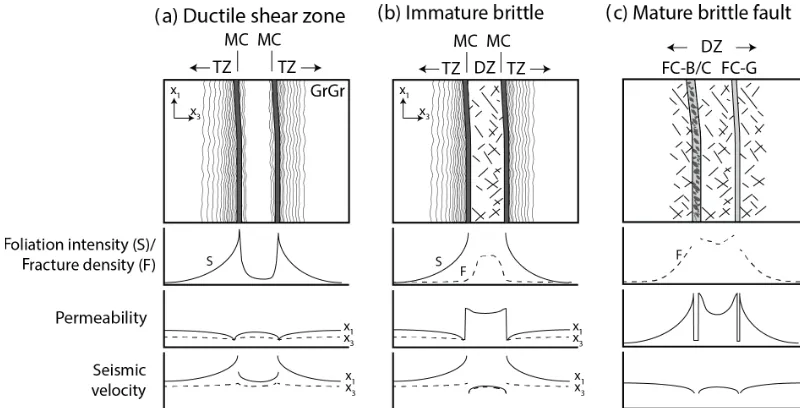
Figure 5.Conceptual model for the characteristics of faults in crystalline rock and their associated petrophysical properties during transition from ductile to brittle deformation conditions. (a)Formation of ductile shear zones with increasing foliation in the transition zone (TZ) nearest the mylonitic core (MC),(b)immature brittle fault with ductile transition zone preserved outside the MCs and the damage zone (DZ) between, and(c)mature brittle fault and DZ, where the brittle features dominate the fluid flow and elastic properties near the brittle fault cores dominated by gouge (FC-G) and breccia/cataclasite (FC-B/C) (after Faulkner et al., 2010).
2010). This case study from the GTS is a hybrid between the two end-member systems.
During the two ductile deformation phases, slip was ac-commodated along localized foliated shear zones that are mylonitic and ultramylonitic (Challandes et al., 2008; Rol-land et al., 2009; Belgrano et al., 2016; Wehrens et al., 2016, 2017). The transition from highly foliated and extremely re-crystallized mylonitic cores towards the host granodiorite represents a strain gradient, which is ∼0.5 m thick in this study (Fig. 5a). The highest foliation intensity in the gra-nodiorite nearest the mylonitic core also creates a change in bulk mineralogy (i.e., more phyllosilicates and less tec-tosilicates; Fig. 3) and microstructure (i.e., more laminated; Figs. 1d and 2), which alter the petrophysical properties that, once frozen in, behave as those measured in the transition zone and mylonitic core in this study (i.e., higher seismic velocity parallel to foliation and lower permeability near-est the mylonitic core). Fluid flow channelization in ductile shear zones have been argued based on mobile elements (Ca, Mg, Na, and K) concentration, stabile isotopes (δ18O), and fluid phase observations (Etheridge et al., 1983; Marquer and Burkhard, 1992). However, in this study and the study by Géraud et al. (1995) the lowest-permeability measurements come from the mylonitic core. While the current measure-ments come from the frozen-in ductile microstructure, dy-namic porosity changes might be occurring during deforma-tion (e.g., Mancktelow et al., 1998), which could enhance the permeability in the mylonitic core. It is possible that the ductile shear zone would behave in such a way that the long-term permeability of the shear zone is low, creating a pressure
seal. Then, during rupture, the seal releases pore pressure and causes short-term permeability enhancement in the form of microfractures and micropores around grains. This is corrob-orated by fractures in the feldspar grains while at conditions with quartz recrystalization.
The later stages of brittle deformation formed along the suitably oriented ductile shear zones resulting in the current fault zone geometry at the GTS shear zone (Fig. 5b). The brittle deformation is bounded by the mylonitic cores. Due to the lack of damage outside these mylonitic cores, this sys-tem is believed to be an “immature” fault, with minimal brit-tle slip. Outside the mylonitic cores the properties are gov-erned by the frozen-in ductile structures. Inside the mylonitic cores the properties are heterogeneously dispersed due to the macrofractures and their associated small-scale microfrac-tures, which reduce the seismic velocity. Recent borehole measurements from pump tests in the damage zone indi-cate that the transmissivity in the damage zone is∼10−8to 10−7m2s−1, while the host granodiorite has a transmissivity of∼10−13to 10−12m2s−1(Jalali et al., 2017).
brittle damage zone. The fault core in such a brittle fault typi-cally has lower permeability than the surroundings due to the clay minerals in the gouge, cataclasite, or fault breccia (e.g., Jefferies et al., 2006; Scholz, 1988; Leclère et al., 2015).
As rocks are exhumed and cooled, this system would tran-sition from the ductile shear zone to a brittle damage zone. Thus, their mechanical properties and how fluids percolate through the entire shear zone would be highly dependent on the transient condition (depth or fault maturity) in which the fault occurs.
5.3 Implication for geothermal energy production and waste disposal
In crystalline rocks the elastic, mechanical, and fluid flow properties are important characteristics for the successful ex-ploitation of natural resources. Mechanically, bulk strain can localize in the fault zone and the mechanical properties can govern earthquake rupture and fracture propagation. In terms of fluid flow, fault zones can act as both fluid conduits and barriers (e.g., Caine et al., 1996). These can be significant in terms of building or releasing pore fluid pressures closely coupled to earthquake rupture (Sibson, 1990; Leclère et al., 2015). The elastic, mechanical, and fluid flow properties of fault zones are also directly linked to geothermal projects (Rowland and Sibson, 2004), as well as the security of long-term waste storage (Barton et al., 1993; Hudson et al., 2011). With the technological advance of horizontal drilling and hy-draulic fracturing the influence and interplay of mechanical and fluid flow anisotropy and heterogeneity are important when addressing stimulation in structurally complex envi-ronments (e.g., Smart et al., 2014; Busetti et al., 2014).
The case at GTS emphasizes the interplay between prop-erties controlled by matrix mineral and fracture-controlled properties. The shear zone at GTS serves as a proxy structure expected in a geothermal reservoir. Understanding the orien-tation of subsurface foliation and proximity to shear zones can assist the efficiency of energy production. The interplay of matrix and fracture flow in such systems should be con-sidered as an additional complexity. When considering the circulation of fluids, well placement in a geothermal injec-tion/production system would need to address the geometry of subsurface heterogeneities. Present-day hydrothermal flu-ids in the Grimsel region flow in “pipe”-like channels (i.e., they are not uniform across the shear zone) (Belgrano et al., 2016). Mapping such structures in a crystalline basement will prove to be a challenge for the successful development of geothermal energy as a resource. Hydraulic stimulation is al-most certainly required to enhance fluid flow in such crys-talline systems. Mechanical anisotropy and heterogeneous pore geometries have been shown to have considerable in-fluence on damage evolution and failure mode (e.g., Rawling et al., 2002; Baud et al., 2005; Griffiths et al., 2017). The importance of understanding the effect of mechanical dis-continuities on hydraulic stimulation is shown with
numer-ical models of damage propagation across mechannumer-ical layers (e.g., Smart et al., 2014). The heterogeneous and anisotropic elastic and fluid flow properties at GTS show that mechani-cal/elastic foliation heterogeneity must be determined, along with stress magnitude and orientation when planning the op-timal borehole placement, trajectory, and stimulation design. The low permeability in the ductile mylonitic cores measured in this study suggest that there might be significant compart-mentalization around such structures.
6 Conclusions
The shear zone at the GTS displays contrasting behavior in a single shear zone due to the fault evolution from ductile to brittle deformation. The ductile history is frozen in out-side the mylonitic cores and is characterized by a transition zone of increasing foliation intensity from the host granodi-orite towards the mylonitic cores. In the transition zone, the seismic velocity of the foliation-parallel samples increases towards the mylonitic core, while the velocity perpendicular to the foliation remains fairly constant. The permeability is also anisotropic and is lower in the samples nearest to and within the mylonitic core, suggesting that both permeability and seismic velocities in the transition zone are greatly influ-enced by the amount and texture of phyllosilicates in the rock mass. Recent brittle deformation is bounded between the fo-liated mylonitic cores and constitutes macroscopic fractures and associated microfractures that rarely penetrate through the mylonitic cores.
The evolution of the system from the formation of the lo-calized shear zones in the earliest observed ductile regime (ca. 21 Ma) and the current brittle regime follows three steps: (1) the localization of ductile deformation, (2) shearing along the rheological discontinuity causing higher foliation inten-sity in the granodiorite nearest to and mylonitization of the mylonitic core, and (3) subsequent brittle deformation along the foliated mylonitic cores. We hypothesize that the prop-erties of this shear zone suggest that brittle deformation is immature in the sense that the overprint has not effected the ductile transition zone.
Encountering such structures in geothermal reservoirs or waste disposal sites would prove to be challenging. The elas-tic, mechanical, and fluid flow heterogeneity caused by the mylonitic cores and their juxtaposition to a brittle damage zone would need to be considered for the optimal engineer-ing design of any reservoir usage system.
Competing interests. The authors declare that they have no conflict of interest.
Acknowledgements. The seismic velocity and permeability exper-iments were performed in the Rock Deformation Laboratory at ETH Zurich. We thank Andrea Moscariello for allowing us to use the QEMSCAN analysis at the University of Geneva. The Swiss National Science Foundation research grant NRP-70 (Exploration and characterization of deep underground reservoirs) provided funding for this project. This study is part of the Grimsel ISC project, established by the Swiss Competence Center for Energy Research – Supply of Electricity (SCCER-SoE) with the support of the Swiss Commission for Technology and Innovation (CTI). Florian Amann, Evangelos Moulas, Valentin Gischig, Joseph Doetsch, Reza Jalali, and Hannes Krietsch are thanked for their comments and assistance during the course of this study. The authors are grateful to Telemaco Tesei and to the anonymous referee for their constructive comments that improved this paper.
Edited by: Bernhard Grasemann
Reviewed by: Telemaco Tesei and one anonymous referee
References
Allen, M., Tatham, D., Faulkner, D., Mariani, E., and Boulton, C.: Permeability and seismic velocity and their anisotropy across the Alpine Fault, New Zealand: an insight from laboratory mea-surements on core from the Deep Fault Drilling Project phase 1 (DFDP-1), J. Geophys. Res.-Solid Earth, 122, 6160–6179, https://doi.org/10.1002/2017JB014355, 2017.
Almqvist, B. S. and Mainprice, D.: Seismic properties and anisotropy of the continental crust: Predictions based on min-eral texture and rock microstructure, Rev. Geophys., 55, 367– 433, https://doi.org/10.1002/2016RG000552, 2017.
Amann, F., Gischig, V., Evans, K., Doetsch, J., Jalali, R., Val-ley, B., Krietsch, H., Dutler, N., Villiger, L., Brixel, B., Klepikova, M., Kittilä, A., Madonna, C., Wiemer, S., Saar, M. O., Loew, S., Driesner, T., Maurer, H., and Giardini, D.: The seismo-hydromechanical behavior during deep geothermal reservoir stimulations: open questions tackled in a decameter-scale in situ stimulation experiment, Solid Earth, 9, 115–137, https://doi.org/10.5194/se-9-115-2018, 2018.
Barton, C. C., Larsen, E., Page, W., and Howard, T.: Characteriz-ing fractured rock for fluid-flow, geomechanical, and paleostress modeling: Methods and preliminary results from Yucca Moun-tain, Nevada, Report, Geological Survey, Denver, CO, USA, 1– 62, 1993.
Baud, P., Louis, L., David, C., Rawling, G. C., and Wong, T.-F.: Ef-fects of bedding and foliation on mechanical anisotropy, damage evolution and failure mode, Geological Society, London, Special Publications, 245, 223–249, 2005.
Belgrano, T. M., Herwegh, M., and Berger, A.: Inherited struc-tural controls on fault geometry, architecture and hydrothermal activity: an example from Grimsel Pass, Switzerland, Swiss J. Geosci., 1–20, 2016.
Birch, F.: The Velocity of Compressional Waves in Rocks to 10 Kilobars, Part 1, J. Geophys. Res., 65, 1083–1102, 1960.
Birch, F.: The velocity of compressional waves in rocks to 10 kilo-bars: 2, J. Geophys. Res., 66, 2199–2224, 1961.
Bolognesi, F. and Bistacchi, A.: Weakness and mechanical anisotropy of phyllosilicate-rich cataclasites developed after my-lonites of a low-angle normal fault (Simplon Line, Western Alps), J. Struct. Geol., 83, 1–12, 2016.
Brace, W., Walsh, J., and Frangos, W.: Permeability of granite under high pressure, J. Geophys. Res., 73, 2225–2236, 1968.
Busetti, S., Jiao, W., and Reches, Z.: Geomechanics of hydraulic fracturing microseismicity: Part 1. Shear, hybrid, and tensile events, AAPG Bulletin, 98, 2439–2457, 2014.
Caine, J. S., Evans, J. P., and Forster, C. B.: Fault zone architecture and permeability structure, Geology, 24, 1025–1028, 1996. Challandes, N., Marquer, D., and Villa, I. M.: PTt modelling, fluid
circulation, and 39 Ar-40 Ar and Rb-Sr mica ages in the Aar Massif shear zones (Swiss Alps), Swiss J. Geosci., 101, 269– 288, 2008.
Chester, F. and Logan, J.: Implications for mechanical properties of brittle faults from observations of the Punchbowl fault zone, California, Pure Appl. Geophys., 124, 79–106, 1986.
David, C. and Wassermann, J.: The KG2B Project: A World-Wide Benchmark of Low Permeability Measurement, Poromechanics VI: Proceedings of the Sixth Biot Conference on Poromechanics, 1153–1161, 2017.
Dicker, A. and Smits, R.: A practical approach for determining per-meability from laboratory pressure-pulse decay measurements, in: International meeting on petroleum engineering, Soc. Petrol. Eng J., SPE 17578, 285–292, 1988.
Donath, F. A.: Experimental study of shear failure in anisotropic rocks, Geol. Soc. Am. Bull., 72, 985–989, 1961.
Etheridge, M., Wall, V., and Vernon, R.: The role of the fluid phase during regional metamorphism and deformation, J. Metamorph. Geol., 1, 205–226, 1983.
Faulkner, D. and Armitage, P.: The effect of tectonic environment on permeability development around faults and in the brittle crust, Earth Planet. Sci. Lett., 375, 71–77, 2013.
Faulkner, D. and Rutter, E.: The gas permeability of clay-bearing fault gouge at 20◦C, Geological Society, London, Special Publi-cations, 147, 147–156, 1998.
Faulkner, D., Lewis, A., and Rutter, E.: On the internal structure and mechanics of large strike-slip fault zones: field observations of the Carboneras fault in southeastern Spain, Tectonophysics, 367, 235–251, 2003.
Faulkner, D., Mitchell, T., Healy, D., and Heap, M.: Slip on ‘weak’ faults by the rotation of regional stress in the fracture damage zone, Nature, 444, 922–925, 2006.
Faulkner, D., Jackson, C., Lunn, R., Schlische, R., Shipton, Z., Wib-berley, C., and Withjack, M.: A review of recent developments concerning the structure, mechanics and fluid flow properties of fault zones, J. Struct. Geol., 32, 1557–1575, 2010.
Fountain, D. M., Hurich, C. A., and Smithson, S. B.: Seismic re-flectivity of mylonite zones in the crust, Geology, 12, 195–198, 1984.
Griffiths, L., Heap, M. J., Xu, T., Chen, C.-f., and Baud, P.: The influence of pore geometry and orientation on the strength and stiffness of porous rock, J. Struct. Geol., 96, 149–160, 2017. Griffiths, L., Lengliné, O., Heap, M., Baud, P., and Schmittbuhl,
wave velocity, coda wave interferometry, and acoustic emissions, J. Geophys. Res.-Solid Earth, 123, 2246–2261, 2018.
Géraud, Y., Caron, J.-M., and Faure, P.: Porosity network of a duc-tile shear zone, J. Struct. Geol., 17, 1757–1769, 1995.
Hsieh, P., Tracy, J., Neuzil, C., Bredehoeft, J., and Silliman, S.: A transient laboratory method for determining the hydraulic prop-erties of ‘rocks’ – I. Theory, in: International Journal of Rock Mechanics and Mining Sciences & Geomechanics Abstracts, vol. 18, 245–252, Elsevier, 1981.
Hudson, J. A., Cosgrove, J. W., Kemppainen, K., and Johansson, E.: Faults in crystalline rock and the estimation of their mechanical properties at the Olkiluoto site, western Finland, Eng. Geol., 117, 246–258, 2011.
Jalali, M., Gischig, V., Doetsch, J., Krietsch, H., Amann, F., and Klepikova, M.: Mechanical, Hydraulic and Seismological Be-havior of Crystalline Rock as a Response to Hydraulic Fractur-ing at the Grimsel Test Site, in: ProceedFractur-ings of 51st US Rock Mechanics/Geomechanics Symposium, San Francisco, Califor-nia, USA, ARMA 17-0962, 1–9, 2017.
Jefferies, S., Holdsworth, R., Wibberley, C., Shimamoto, T., Spiers, C., Niemeijer, A., and Lloyd, G.: The nature and importance of phyllonite development in crustal-scale fault cores: an example from the Median Tectonic Line, Japan, J. Struct. Geol., 28, 220– 235, 2006.
Jones, T. and Nur, A.: Seismic velocity and anisotropy in mylonites and the reflectivity of deep crystal fault zones, Geology, 10, 260– 263, 1982.
Jones, T. and Nur, A.: The Nature of Seismic Reflections From Deep Crustal Fault Zones, J. Geophys. Res., 89, 3153–3171, 1984. Kern, H. and Wenk, H.-R.: Fabric-Related Velocity Anisotropy and
Shear Wave Splitting in Rocks From the Santa Rosa Mylonite Zone, California, J. Geophys. Res., 95, 11213–11223, 1990. Keusen, H., Ganguin, J., Schuler, P., Buletti, M., and Geotest:
Grim-sel Test Site: Geology, Report, 1–166, 1989.
Klinkenberg, L.: The permeability of porous media to liquids and gases, in: Drilling and production practice, American Petroleum Institute, 200–213, 1941.
Krietsch, H., Gischig, V., Jalali, M., Amann, F., Evans, K., Doetsch, J., and Valley, B.: Stress measurements in crystalline rock: Comparison of overcoring, hydraulic fracturing and induced seismicity results, in: Proceedings of 51st US Rock Mechan-ics/Geomechanics Symposium, San Francisco, California, USA, ARMA-17-0733, 1–8, 2017.
Leclère, H., Cappa, F., Faulkner, D., Fabbri, O., Armitage, P., and Blake, O.: Development and maintenance of fluid overpressures in crustal fault zones by elastic compaction and implications for earthquake swarms, J. Geophys. Res.-Solid Earth, 120, 4450– 4473, 2015.
Lloyd, G., Butler, R., Casey, M., Tatham, D., and Mainprice, D.: Constraints on the seismic properties of the middle and lower continental crust, Geological Society, London, Special Publica-tions, 360, 7–32, https://doi.org/10.1144/SP360.2, 2011a. Lloyd, G., Halliday, J., Butler, R., Casey, M., Kendall, J.,
Wookey, J., and Mainprice, D.: From crystal to crustal: petrofabric-derived seismic modelling of regional tectonics, Ge-ological Society, London, Special Publications, 360, 49–78, https://doi.org/10.1144/SP360.4, 2011b.
Mainprice, D.: Seismic Anisotropy of the Deep Earth from a Min-eral and Rock Physics Perspective, Treatise in Geophysics – Vol-ume 2 Mineral Physics, 437–482, 2007.
Mancktelow, N. S., Grujic, D., and Johnson, E. L.: An SEM study of porosity and grain boundary microstructure in quartz mylonites, Simplon Fault Zone, Central Alps, Contrib. Mineral. Petr., 131, 71–85, 1998.
Marquer, D. and Burkhard, M.: Fluid circulation, progressive defor-mation and mass-transfer processes in the upper crust: the exam-ple of basement-cover relationships in the External Crystalline Massifs, Switzerland, J. Struct. Geol., 14, 1047–1057, 1992. Mavko, G., Mukerji, T., and Dvorkin, J.: Rock Physics Handbook:
Tools for Seismic Analysis of Porous Media, 2nd Edition, Cam-bridge University Press, p. 524, 2009.
Mitchell, T. and Faulkner, D.: The nature and origin of off-fault damage surrounding strike-slip fault zones with a wide range of displacements: a field study from the Atacama fault system, northern Chile, J. Struct. Geol., 31, 802–816, 2009.
Mitchell, T. and Faulkner, D.: Towards quantifying the matrix per-meability of fault damage zones in low porosity rocks, Earth Planet. Sci. Lett., 339, 24–31, 2012.
Morrow, C., Lockner, D., Hickman, S., Rusanov, M., and Röckel, T.: Effects of lithology and depth on the permeability of core samples from the Kola and KTB drill holes, J. Geophys., 99, 7263–7274, 1994.
NIST: http://webbook.nist.gov/chemistry/fluid/ (last access: 30 June 2017), National Institute of Standards and Technology, 2017.
Nur, A. and Simmons, G.: The effect of saturation on velocity in low porosity rocks, Earth Planet. Sc. Lett., 7, 183–193, 1969. Pini, R., Ottiger, S., Burlini, L., Storti, G., and Mazzotti, M.:
Role of adsorption and swelling on the dynamics of gas injection in coal, J. Geophys. Res.-Solid Earth, 114, 1–14, https://doi.org/10.1029/2008JB005961, 2009.
Rawling, G. C., Baud, P., and Wong, T.: Dilatancy, brittle strength, and anisotropy of foliated rocks: Experimental deformation and micromechanical modeling, J. Geophys. Res.-Solid Earth, 107, 1–14, https://doi.org/10.1029/2001JB000472, 2002.
Rey, P. F., Fountain, D. M., and Clement, W. P.: P wave velocity across a noncoaxial ductile shear zone and its associated strain gradient: Consequences for upper crustal reflectivity, J. Geophys. Res., 99, 4533–4548, 1994.
Rolland, Y., Cox, S. F., and Corsini, M.: Constraining deformation stages in brittle–ductile shear zones from combined field map-ping and 40 Ar/39 Ar dating: the structural evolution of the Grim-sel Pass area (Aar Massif, Swiss Alps), J. Struct. Geol., 31, 1377– 1394, 2009.
Rowland, J. and Sibson, R.: Structural controls on hydrothermal flow in a segmented rift system, Taupo Volcanic Zone, New Zealand, Geofluids, 4, 259–283, 2004.
Schaltegger, U. and Corfu, F.: The age and source of late Hercynian magmatism in the central Alps: evidence from precise U-Pb ages and initial Hf isotopes, Contrib. Mineral. Petr., 111, 329–344, 1992.
Scholz, C.: The brittle-plastic transition and the depth of seismic faulting, Geol. Rundsch., 77, 319–328, 1988.
Sibson, R. H.: Rupture nucleation on unfavorably oriented faults, B. Seismol. Soc. Am., 80, 1580–1604, 1990.
Sibson, R. H.: Crustal stress, faulting and fluid flow, Geological So-ciety, London, Special Publications, 78, 69–84, 1994.
Siegesmund, S., Kern, H., and Vollbrecht, A.: The effect of oriented microcracks on seismic velocities in an ultramylonite, Tectono-physics, 186, 241–251, 1991.
Smart, K. J., Ofoegbu, G. I., Morris, A. P., McGinnis, R. N., and Ferrill, D. A.: Geomechanical modeling of hydraulic fracturing: Why mechanical stratigraphy, stress state, and pre-existing struc-ture matter, AAPG Bulletin, 98, 2237–2261, 2014.
Sone, H. and Zoback, M. D.: Mechanical properties of shale-gas reservoir rocks – Part 1: Static and dynamic elas-tic properties and anisotropy, Geophysics, 78, D378–D389, https://doi.org/10.1190/Geo2013-0050.1, 2013.
Steck, A.: Die alpidischen Strukturen in den Zentralen Aaregran-iten des westlichen Aarmassivs, Eclogae Geol. Helv., 61, 19–48, 1968.
Uehara, S.-I. and Shimamoto, T.: Gas permeability evolution of cataclasite and fault gouge in triaxial compression and implica-tions for changes in fault-zone permeability structure through the earthquake cycle, Tectonophysics, 378, 183–195, 2004. Vermilye, J. M. and Scholz, C. H.: A microstructural view of fault
growth, J. Geophys. Res., 103, 12223–12237, 1998.
Vidal, J. and Genter, A.: Overview of naturally permeable fractured reservoirs in the central and southern Upper Rhine Graben: In-sights from geothermal wells, Geothermics, 74, 57–73, 2018. Violay, M., Heap, M., Acosta, M., and Madonna, C.: Porosity
evo-lution at the brittle-ductile transition in the continental crust: Im-plications for deep hydro-geothermal circulation, Sci. Rep., 7, 1–10, https://doi.org/10.1038/s41598-017-08108-5, 2017.
Watanabe, N., Numakura, T., Sakaguchi, K., Saishu, H., Okamoto, A., Ingebritsen, S. E., and Tsuchiya, N.: Potentially exploitable supercritical geothermal resources in the ductile crust, Nat. Geosci., 10, 140–144, https://doi.org/10.1038/ngeo2879, 2017. Wehrens, P., Berger, A., Peters, M., Spillmann, T., and Herwegh,
M.: Deformation at the frictional-viscous transition: Evidence for cycles of fluid-assisted embrittlement and ductile deformation in the granitoid crust, Tectonophysics, 693, 66–84, 2016.
Wehrens, P., Baumberger, R., Berger, A., and Herwegh, M.: How is strain localized in a meta-granitoid, mid-crustal basement sec-tion? Spatial distribution of deformation in the central Aar massif (Switzerland), J. Struct. Geol., 94, 47–67, 2017.
Wenning, Q. C., Madonna, C., de Haller, A., and Burg, J.-P.: Dataset for “Permeability and seismic velocity anisotropy across a ductile-brittle fault zone in crystalline rock”, https://doi.org/10.3929/ethz-b-000245921, 2018.
Wibberley, C. A. and Shimamoto, T.: Internal structure and perme-ability of major strike-slip fault zones: the Median Tectonic Line in Mie Prefecture, Southwest Japan, J. Struct. Geol., 25, 59–78, 2003.
Wilson, J., Chester, J., and Chester, F.: Microfracture analysis of fault growth and wear processes, Punchbowl Fault, San Andreas system, California, J. Struct. Geol., 25, 1855–1873, 2003. Zappone, A., Fernandez, M., Garcia-Duenas, V., and Burlini,