ISSN: 2231-5381
http://www.ijettjournal.org
Page 130
Design Modification and Comparative
analysis of Multistage Submersible Pump
Diffuser
Prof. Naitik L. Mehta#1, Prof. Nikunj B. Vaishnav *2, Prof. Ronak M. Kamdar#3 #Assistant Professor, Mechanical Engineering Department, Marwadi Education Foundation’s
Group of Institutions, Rajkot-Morbi Road, PO : Gauridad, Rajkot 360003, Gujarat, India. *Assistant Professor, Mechanical Engineering Department, Marwadi Education Foundation’s
Group of Institutions, Rajkot-Morbi Road, PO : Gauridad, Rajkot 360003, Gujarat, India. #Assistant Professor, Mechanical Engineering Department, Marwadi Education Foundation’s
Group of Institutions, Rajkot-Morbi Road, PO : Gauridad, Rajkot 360003, Gujarat, India.
Abstract
This paper is explaining safe design modification and analysis of diffuser to save material in production. The diffuser is used for flow directing properties by reducing the velocity and increasing the static pressure of a fluid passing in submersible pump. In Submersible pump each stage consists of a rotating impeller and stationary diffuser.
Key words:Diffuser, Submersible Pump, Impeller
1. Electrical Submersible Pump
The electrical submersible pump (ESP) is a type of centrifugal pump. Which is classified as a multistage vertical pump with a Diffuser.
ESP literally works submersed into the fluid, since it is installed within a cased hole well from which the fluid is produced.[4]
An ESP is a multistage centrifugal pump. Each stage basically consists of two parts: a diffuser and an impeller as shown in figure 1.1.
Figure – 1.1 Diffuser Assembly[1]
The impeller is mounted on a rotating shaft and can be considered as the moving part. The fluid particles are gradually accelerated increasing the kinetic energy.The diffuser is a stationary part that consists of a series of stationary passages with cross-sectional areas that gradually decrease.Thus, the kinetic energy is converted to pressure or head in the impeller and the diffuser.
2. Diffuser Material
Generally Diffuser is made of the Stainless steel 304 grade materials. Stainless steels are high-alloy steels that have superior corrosion resistance than other steels because they contain large amounts of chromium. Diffuser is made by the process of Investment casting.
Physical Properties of Stainless Steel 304:
Typical compositional ranges for grade 304 stainless steels are given in table – 2.1.
Table – 2.1 Physical Properties of SS 304[7]
Grade C Mn Si P S Cr Mo Ni N
304 min. - - - 18 - 8 -
max. 0.08 2 0.75 0.045 0.03 20 10.5 0.1
304L min. - - - 18 - 8 -
max. 0.03 2 0.75 0.045 0.03 20 12 0.1
0.045
max. 0.1 2 0.75 0.03 20 10.5
Mechanical Properties of Stainless Steel 304:
Typical mechanical properties for grade 304 stainless steels are given in table – 2.2. Table - 2.2 Mechanical Properties of SS 304[7]
Grade
Tensile Strength (MPa) min
Yield Strength 0.2% Proof (MPa) min
Elongation (%
in50mm) min Hardness
Rockwell B (HRB) max
Brinell (HB) max
304 515 205 40 92 201
304L 485 170 40 92 201
ISSN: 2231-5381
http://www.ijettjournal.org
Page 132
3. Design Procedure of Diffuser
The Procedure of design the radial flow Diffuser is same, only some data will be changed on the basis of size of the Diffuser. Diffuser is designed on the basis ofdesign flow rate, pump head and pump specific speed. So, thedesign data are required to design the FRS 80 Diffuser[5] is taken as follow: .
Q = 0.0033 m3/s H = 11.5 m N = 2800 RPM 𝑔 = 9.81 m/s2
𝜌 = 1000 kg/m3for Water β1 = 210
β2= 240
Hvel = 4.05 m
Now for finding the Peripheral velocity at inlet and outlet of the Diffuser we have,
Peripheral velocity at inlet,
u1= ω × R1
= 2𝑁𝜋
60 × R1
=2 × 2800 × 𝜋
60 × 0.025
= 7.33 m/s
Similarly Peripheral velocity at outlet,
u2= ω × R2
=2 × 2800 × 𝜋
60 × 0.059
= 17.30 m/s
Water velocity at the outlet of the Diffuser,
Vout =
Q
H π − 1.5 t × b2
= 3300
11.5 π − 1.5 × 2.5 × 0.5
= 2.3 m/s
Now finding the static head and Theoretical head of the pump from which we can calculate the Total Head,
Hst =
u2 − 2 u1 − 2 (Vout × Cotβ12)
2g = 17.30
2− 7.332− (2.3 × 6.25)
19.62
= 10.64 meter
Hth = Hvel + Hst
= 4.05 + 10.64
= 14.69 meter
Hnet = 0.92 × Hst × 0.4 × Hvel
= 0.92 × 10.64 × 0.4 × 4.05
= 11.4 meter
Now finding the Horse Power,
HP = Hth × Q
75 × η
= 14.69 × 3.3
75 × 0.93
= 0.69 HP
Checking for the Design stress of the Diffuser
Design stress = Yield Point Stress
Factor of safety
= 215
1.15
= 187 N mm2
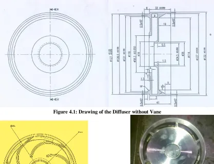
4. Modelling of the Diffuser of Mutistage Submersible Pump
Figure 4.1: Drawing of the Diffuser without Vane
Figure 4.2: Drawing of Vane of Diffuser
Figure 4.4: Bottom View of Diffuser
Figure 4.5: Assembly of Diffuser
ISSN: 2231-5381
http://www.ijettjournal.org
Page 134
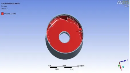
5. Pressure Measurement
Pressure is measured on the basis of the static head of the pump which is in meter. So up to the static head value the flow of pressurized fluid is lifted and at that level with the help of pressure gauge arrangement value of pressure can be measured.
As from the above discussion by testing the V8 submersible pump for the fluid (water) pressure, the pressure is resulted 400 psi for the static head value 10.64 meter in the pressure gauge. So with the help pressure unit conversion table we can convert the psi unit into the Mpa as under.[6]
1 psi = 6.894 × 10³ pa
= 400 × 6.894 × 103
= 2.75 × 10⁶pa
So from the above calculation we get the pressure value as 2.75 Mpa. We can consider it as 2.8 Mpa. 6. Boundary conditions
Boundary conditions are imposed on solid walls (no slip), on periodic boundaries, at inlet (total pressure) and flow anglesandoutlet (static pressure) of the computational domain.
Diffuser is a stationary part so the surface which is at the bottom and upper area of the diffuser will not be in contact with the fluid those surfaces are fixed. Fixed support at bottom and upper surfaces of diffuser are shown in figures 6.1 and 6.2 simultaneously.
Figure 6.1 Fixed support condition given to bottom side of Diffuser
Figure 6.2 Fixed support condition given to top side of Diffuser
Application of Pressure
Diffuser is a stationary part so the surface which is at the bottom and upper area of the diffuser will get pressure from the fluid those surfaces are given pressure.
Figure 6.3 Pressure applied at top side of Diffuser
Pressure applied at bottom and upper surfaces of diffuser are shown in figures 6.3 and 6.4 simultaneously.
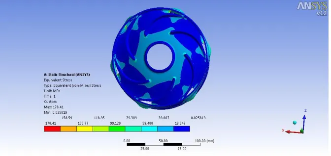
7. Analysis of Diffuser
Diffuser is a stationary part of the pump so for the optimization we can consider static structural analysis of Diffuser. ANSYS Mechanical provides solutions for many types of analyses including structural, thermal, modal, linear buckling and shape optimization studies.[3]
Case-I: O.D. of Diffuser = 132 mm
After applying the pressure at the surfaces we can solve the model. By solving the model analysis we get Equivalent stress as an output result which is as 147.4 Mpa for the 132 mm outer diameter Diffuser which is less than the safe design stress 187 Mpa. Figure 7.1 describes the result of the Equivalent stress results of Diffuser of 132 mm outer diameter.
Figure 7.1 Equivalent Stress results of Diffuser of 132 mm outer diameter
So according to the Safe design stress calculation we can consider this 132 mm outer diameter design as an over safe design. So we can optimize this outer diameter of the Diffuser.
Case-II: O.D. of Diffuser = 130.5 mm
After applying the pressure at the surfaces we can solve the model. By solving the model analysis we get Equivalent stress as an output result which is as 178.41 Mpa for the 130.5 mm outer diameter Diffuser which is less than the safe design stress 187 Mpa. Figure 7.2 describes the result of the Equivalent stress results of Diffuser of 130.5 mm outer diameter.
7.2 Equivalent Stress results of Diffuser of 130.5 mm outer diameter
So according to the Safe design stress calculation we can consider this 130.5 mm outer diameter design as a safe design.
Case-III: O.D. of Diffuser = 129.5 mm
ISSN: 2231-5381
http://www.ijettjournal.org
Page 136
187 Mpa. Figure 7.3 describes the result of the Equivalent stress results of Diffuser of 129.5 mm
outer diameter.
7.3 Equivalent Stress results of Diffuser of 129.5 mm outer diameter
So according to the Safe design stress calculation we cannot consider this 129.5 mm outer diameter design as a safe design.
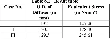
8. Results & Discussion
From the above analysis of the Case I, II and III we can get the Equivalent stress as an output result which is described in the below table 8.1.
Table 8.1 Result table Case No. O.D. of
Diffuser (in mm)
Equivalent Stress (in N/mm2)
I 132 147.40
II 130.5 178.40
III 129.5 245.61
From the above table we can conclude as under: I. In Case – I the Equivalent stress is 147.40
which is less than the safe design stress 187 Mpa. So according to the Safe design stress calculation we can consider this 132 mm outer diameter design as an over safe design. II. In Case – IIthe Equivalent stress is 178.40 which is less than the safe design stress 187 Mpa. So according to the Safe design stress calculation we can consider this 130.5 mm outer diameter design as a safe design. III. In Case – IIthe Equivalent stress is 245.61
which is greater than the safe design stress 187 Mpa. So according to the Safe design stress calculation we cannot consider this 129.5 mm outer diameter design as a safe design.
So from the above discussion we can get the result if we reduce the outer diameter of the diffuser from 132 mm to 130.5 than it will be a safe design and 129.5 outer diameter will not be the safe design.
9. Conclusion
By considering the design of Diffuser, the static structural analysis is done for the modification of Diffuser. So the outer diameter can be modified considering the safe design stress from the Analysis. There are three different cases considered, Case – I describes the over safe design with original outer diameter of Diffuser where in Case – II describes the fail design by reducing the outer diameter of Diffuser because in the Case – II the equivalent stress resulted is greater than the safe design stress. At the end in Case – III
So after considering the results of the three different cases, the modification of Diffuser can be done by considering the safe design stress value and the pressure of the fluid.
10. Nomenclatures
Q = Flow rate of Water inm3/s H = Head in meter
N = Speed of motor in RPM
g = Gravitational acceleration in m/s2 ρ = Density of Water in kg/m3 β1 = Angle of vane at inlet
β2 = Angle of vane at outlet
D1= Outer diameter of Diffuser in mm
D2= Inner diameter of Diffuser in mm
Vout = Velocity of water at outlet m/s
P = Pressure at the inlet of Diffuser Mpa u1= Peripheral velocity of Impeller at Inlet m/s
u2= Peripheral velocity of Impeller at outlet m/s
ω = Angular Velocity in rad/s Hst = Static Head in meter
Hth= Theoretical Head in meter
Hnet = Total Head in meter
11. References
[1]. Zangeneh, M., Goto, A., and Takemura, T., “Suppression
of SecondaryFlows in a Mixed-Flow Pump Impeller by
Application of Three-Dimensional Inverse Design
Method: Part 1 - Design and Numerical Validation,” ASME J.Turbomach., 118, 1996,pp. 536–543.
[2]. Prof. Naitik L. Mehta, Prof. V. P. Darji, Prof.P.H.Darji,
“Design and Modelling of Bowl of Multistage Submersible Pump”,Journal of Information, Knowledge and Research in Mechanical Engineering ISSN 0975 – 668X, NOV 10 TO OCT 11 |VOLUME – 01, ISSUE - 02 Page – 31.
[3]. Juhasz,A.J. “Performance Of An Asymmetric Annular
Diffuser With Non Diverging Inner Wall Using Suction”, 1974, NASA TN -7575.
Books:
[4]. Gabor Takacs, “Electrical Submersible Pumps Manual:
Design, Operations, And Maintenance”, Gulf Professional Publish, Elsevier 30, 2009.
[5]. V.M. Cherkassy, “Pumps Fans Compressors”, Mir
Publication, Moscow.
[6]. G.K. Sahu, “Pumps”, New Age International Publishers,
2008.
[7]. PSG College of Technology, “Design Data”, Kalaikathir –
![Table – 2.1 Physical Properties of SS 304 [7]](https://thumb-us.123doks.com/thumbv2/123dok_us/8586622.1720059/1.595.336.490.271.388/table-physical-properties-ss.webp)
![figure 4.2 as under. Figure 4.3 and figure 4.4 shows the diffuser used in multistage submersible pump.[2]](https://thumb-us.123doks.com/thumbv2/123dok_us/8586622.1720059/3.612.63.526.68.664/figure-figure-figure-shows-diffuser-used-multistage-submersible.webp)