Research article
Available online
www.ijsrr.org
ISSN: 2279–0543
International Journal of Scientific Research and Reviews
Hydro cracking for Maximizing Middle Distillates
Singh Shraddha R., Chaturvedi A
*, Lal Dori, Ranjan A., Lodhi S. K., Singh A., Gola Neeraj
Department of Chemical Engineering, Raja Balwant Singh Engineering Technical Campus, Bichpuri, Agra, Uttar Pradesh, India
ABSTRACT
A simplified description of hydrocracking is the decomposition of hydrocarbons on the acid sites of the catalyst’s support, followed by hydrogenation of the cracking products on the metallic sites. The first stage of this process is analogous to catalytic cracking. Basically, the aim of hydrocracking as well as other cracking processes is the transformation of the heavy fractions of crude oil into light fractions. The use of this process is determined by the high quality of some of the products obtained, such as the jet fuel and the lubricating oils of high viscosity index. It is more expensive than catalytic cracking due to the high price of hydrogen and operation at high pressure. In addition, the role of hydrocracking increased due to the new requirements for gasoline. Following paper reviews this excellent process used in Petroleum Refineries. Hydrocracking plants are capable of processing a wide variety of feedstocks of different characteristics to produce a broad range of products. They can be designed and operated to maximize the production of a gasoline blending component (called hydrocrackate) or to maximize the production of diesel oil.
KEYWORDS:
Hydro cracking, Catalyst, Crude oil, FeedstocksCorresponding
Author:-Anuj Chaturvedi
Department of Chemical Engineering
INTRODUCTION
Hydrocracking is a catalytic chemical process used in petroleum refineries for converting the
high-boiling constituent hydrocarbons in petroleum crude oils to more valuable lower-high-boiling products such as
gasoline, kerosene, jet fuel and diesel oil. The process takes place in a hydrogen-rich atmosphere at elevated
temperatures (260 – 425 °C) and pressures (35 – 200kg/cm2)1, 2. The process consists of causing feed to
react with hydrogen in the presence of a catalyst under specified operating conditions temperature, pressure,
and space velocity. the process cracks the high-boiling, high molecular weight hydrocarbons into
lower-boiling, lower molecular weight olefinic and aromatic hydrocarbons and then hydrogenates them. Any
sulfur and nitrogen present in the hydrocracking feedstock are, to a large extent, also hydrogenated and
form gaseous hydrogen sulfide (H2S) and ammonia (NH3) which are subsequently removed. The result is
that the hydrocracking products are essentially free of sulfur and nitrogen impurities and consist mostly of
paraffinic hydrocarbons. Hydrotreating and Hydrocracking are somewhat similar in nature. Both use
high-pressure hydrogen to catalytically remove contaminants from petroleum fractions. Both achieve at least
same conversion, and they use the same kinds of hardware. Therefore, as is common in the refining
industry, we use the term hydroprocessing when a statement applies to both hydrotreating and
hydrocracking3.
Hydrocracking plants are capable of processing a wide variety of feedstocks of different characteristics to
produce a broad range of products. They can be designed and operated to maximize the production of a
gasoline blending component (called hydrocrackate) or to maximize the production of diesel oil.
Hydrocracker feed is typically heavy diesel boiling above the saleable diesel range or vacuum gas oil
stream originating from the crude and vacuum distillation unit, atmospheric resid desulfurizers, coker units,
solvent de-asphalting units, and the like. The hydrocracking catalyst is very sensitive to certain impurities,
such as nitrogen and metals, and the feed must conform to the specifications laid down by the catalyst
manufacturers to obtain a reasonable catalyst life.
History of Hydrocracking
Hydrocracking was first developed in Germany as early as 1915 to provide liquid fuels derived from
their domestic coal deposits. The first plant that might be considered as a commercial hydrocracking unit
began operation in Leuna, Germany in 1927. Similar efforts to convert coal to liquid fuels took place in the
Great Britain, France and other countries. Between 1925 and 1930, Standard Oil of New Jersey collaborated
°C and were very expensive. Hydrocracking enjoyed rapid growth in the United States during the late 1960s
and the early 1970s3,4. By the mid-1970s, hydrocracking had become a mature process and its growth began
to moderate. From then on, hydrocracking growth in the United States proceeded at a slow pace. However,
at the same time, hydrocracking enjoyed significant growth in Europe, the Asia-Pacific region and the
Middle East. As of 2001, there were about 155 hydrocracker units operating worldwide and processing
about 4,000,000 barrels (550,000 metric tons) per day of feedstock.
PROCESS CONFIGURATION
There are a many different proprietary hydrocracker designs available for use under license as is the
case for many of the other processes used in petroleum refineries. There are also a number of different
hydrocracker process equipment configurations. Depending upon the feed quality, product mix desired and
the capacity of unit, following process flow configurations can be adopted for Hydrocracker4,5:
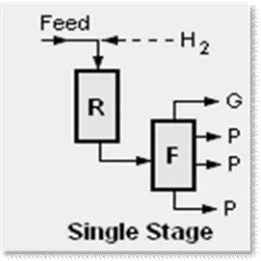
A) Single stage with recycle (For 100% conversion of the feed to products)
This is the most commonly used configuration. The uncracked residual hydrocarbon oil from the
bottom of reaction product fractionation tower is recycled back into the single reactor for further cracking.
Again, for single stage hydrocracking, either the feedstock must first be hydrotreated to remove ammonia
and hydrogen sulfide or the catalyst used in the single reactor must be capable of both hydrotreating and
hydrocracking.
Fig 1: Single stage hydrocracker
B) Two stage (For 100% conversion of the feed to products)
This configuration uses two reactors and the residual hydrocarbon oil from the bottom of reaction
product fractionation tower is recycled back into the second reactor for further cracking. Since the first
free of ammonia and hydrogen sulfide. This permits the use of high performance noble metal (palladium,
platinum) catalysts which are susceptible to poisoning by sulfur or nitrogen compounds.
Fig 2: Two stage hydrocracker
C) Once through (For partial conversion of feed to products, 60%-80%)
This configuration uses only one reactor and any uncracked residual hydrocarbon oil from the
bottom of the reaction product fractionation (distillation) tower is not recycled for further cracking. For
single stage hydrocracking, either the feedstock must first be hydrotreated to remove ammonia and
hydrogen sulfide or the catalyst used in the single reactor must be capable of both hydrotreating and
hydrocracking.
Fig 3: Once Through Hydrocracker
In once through operation, there is no recycle and fractionation bottom is taken as product (FCC feed). In
single stage scheme, the uncovered material from fractionator bottom is recycled to first reactor along with
fresh feed. In the two-stage scheme, the unconverted material is routed separately to another reactor. In both
Table 1: Hydrotreating and Hydrocracking: Ranges of H2 Partial Pressure and Conversion3 :
Process, Feedstock Types H2 Partial Pressure (psig) Conversion (wt%)
Hydrotreating
Naphtha 250-600 0.5-5
LGO(kerosene) 250-600 0.5-5
HGO(diesel) 600-800 5-15
VGO, VBGO 800-2000 5-15
Residual Oil 2000-3000 5-15
Mild Hydrocracking
VGO, VBGO, DAO, LCO 80-1200 20-40
Once Through Hydrocracking
VGO, DAO, CGO, HCO 1500-2000 60-90
Residual Oil 2000-3000 15-25
Recycle Hydrocracking
VGO, VBGO, DAO, HCO 1500-2000 80-99
Note: LGO = light gas oil; HGO = heavy gas oil; LCO = FCC light-cycle oil; HCO = FCC
heavy-cycle oil; VGO = vacuum gas oil; VBGO = visbreaker gas oil; DAO = deasphalted
oil; CGO = coker gas oil.
PROCESS FLOW DIAGRAM OF ONCE THROUGH HYDROCRACKER:
Process Description:
Most hydrotreaters and hydrocrackers are trickle-bed units6. In such units, mixtures of liquid and
gaseous reactants pass down over fixed beds of catalyst. In hydroprocessing units, the liquid reactants are
petroleum fractions, and the gaseous reactant is hydrogen.
Figure 4 shows a flow scheme for a once-through unit designed to process heavy gas oil feeds. Designs
offered by major process licensors can differ in several areas, which correspond to the bold numbers on the
diagram.
1. Heaters. Units with gas-only heaters mix hot gas with preheated liquid feed just before the reactants
enter the first reactor. Other designs use a gas-plus-oil heater to bring the mixed fluids up to reaction
temperature.
2. Reactors, catalyst beds, and quench zones6. Addition of hydrogen typically occurs with heat release, and
most hydroprocessing reactions are exothermic. The heat released in naphtha and kerosene hydrotreaters is
relatively low, so units designed for these feeds may use just one reactor that contains a single catalyst bed.
However, for heavier feeds or feeds that contain large amounts of sulfur, aromatics, or olefins, the total
increase in temperature can exceed 180°F (100°C). It is unsafe to allow that much temperature rise in a
single bed of catalyst. To divide the heat release into smaller, safer portions, commercial units use multiple
catalyst beds with cooling in between. A unit can have one bed per reactor, or multiple beds in each reactor
with quench zones in between. In a quench section hot process fluids from the preceding bed are combined
with relatively cold hydrogen-rich quench gas before the mixture passes into the next bed. We can think of
a catalyst bed as a stack of thin, horizontal discs. Ideally, the top disc is the coolest, the bottom disc is the
hottest, and at every point in each given disc, temperatures are identical. But in real units, the downward
flow of reactants is never perfectly uniform, so the temperatures within the discs are different, especially
near the bottom. The difference between the highest and lowest temperature at the bottom of a catalyst bed
is called the radial temperature difference (RTD). The truth is, we never know the actual highest and lowest
temperatures, because we cannot place thermocouples everywhere. But if the measured RTD is small —
less than 5°F (3°C) — we can assume that the actual RTD is also small, and that flow through the bed is
nearly uniform. If the measured RTD is large, the actual RTD is almost certainly larger, and we have to be
concerned about hot spots, flow blockages, and other potentially dangerous symptoms of maldistribution.
Modern quench sections are designed to do three things:
(1) lower the overall temperature of the reacting fluids,
3. Catalysts8,9. Hydrotreaters are loaded with either a CoMo HDS or NiMo HDN catalyst, or both. NiMo
catalysts are better for the saturation of aromatics, which is required for the removal of hindered sulfur
compounds during deep desulfurization. Therefore, some refiners load a layer of NiMo catalyst on top of a
CoMo catalyst in diesel desulfurization units. Recently, catalyst manufacturers have been offering
trimetallic (CoNiMo) hydrotreating catalysts. Most of the cracking in hydrocracking units is driven by
catalysts with high acidity. The acidic sites are inhibited by organic nitrogen, so the first several catalyst
beds in a hydrocracking unit typically contain a high-activity HDN catalyst. In a few units, all beds in a
hydrocracker are filled with an amorphous dual-function catalyst, which catalyzes both HDN and cracking.
This type of catalyst has a high selectivity for producing middle distillates from VGO.The last bed in a
hydrocracker often contains a final layer of post-treat catalyst to remove mercaptans.
4. Makeup and recycle hydrogen. Compressors for makeup hydrogen are reciprocating machines, most of
which are driven by electric motors. Recycle gas compressors can be reciprocating or centrifugal; the latter
are often driven by steam. In naphtha hydrotreaters, the high-pressure off-gas can be purer than the makeup
gas, because (a) conversion is nil and (b) liquids in the makeup gas are absorbed by the naphtha. In most
other units, the makeup gas is purer than the recycle gas. Makeup hydrogen can enter the unit at the cold
high-pressure separator (CHPS), at the suction of the recycle gas compressor, or at the discharge of the
recycle gas compressor. If the makeup comes in at the CHPS, the makeup compressor discharge pressure is
lower, which can reduce electricity costs. However, if part of the recycle gas is purged after leaving the
CHPS, part of the incoming makeup gas goes right back out again. If the makeup comes in at the discharge
of the recycle gas compressor, the discharge pressure of the makeup compressor is higher, but none of the
high-purity makeup is lost with purge gas.
5. High-pressure amine absorption. Prior to the advent of ultra-low-sulfur fuels, it was rare to find
hydroprocessing units with a high-pressure amine absorber to remove H2S from the recycle gas. H2S
inhibits HDS reactions and lowers the purity of the recycle gas. For both of these reasons, high-pressure
amine absorbers are now included in most new and revamped diesel hydrotreaters and mild hydrocrackers.
6. Product cooling and separation. Commercial units comprise a number of different product cooling and
flash drum configurations. The simplest comprises a feed/effluent heat exchanger train, a large air- or
water-cooled heat exchanger, and one or two flash drums. Heavy-feed units have at least a CHPS and a
through a high-pressure amine absorber for removal of H2S. The CHPS bottoms go to the CLPS11,15.
Sometimes the pressure differential between the CHPS and CLPS is used to drive a power recovery turbine.
7. Wash water addition. As mentioned above, HDS and HDN reactions produce H2S and NH3,
respectively. Wash water is injected into the effluent from the last reactor to convert almost all of the NH3
and some of the H2S into aqueous ammonium bisulfide, NH4HS(aq)10,12. The NH4HS(aq) is rejected from
the unit as sour water in the low-pressure flash drum.
8. Fractionation. For product fractionation, HDS units that treat naphtha or light gas oil may use a simple
steam stripper to remove H2S and traces of light hydrocarbons from the liquid product (CLPS bottoms). An
absorber may be used to recover C3+ compounds from the CLPS overhead. Conversion units may employ a
full-fledged fractionation train, with a preflash tower to remove light ends; an atmospheric fractionator to
separate light naphtha, heavy naphtha, middle distillates, and unconverted oil; and a vacuum tower to
maximize the recovery of diesel.
Some hydrocrackers use the atmospheric tower to produce full-range naphtha, which is then separated into
light and heavy fractions in a naphtha splitter13, 14.
CONCLUSION:
Although industry analysts suggest that cost pressures and depressed refining margins will remain,
there is still significant growth in the hydrocracking market. But still it has emerged as a great field of
research and development since Middle Distillate yield is 80% as compared to 45% in FCCU7. Catalytic
hydrocracking is a versatile process for increasing the hydrogen to carbon ratio and decreasing the
molecular weight of heavy oils. This versatility has proven to be extremely valuable in the search for
optimal processing conditions and catalysts for production of good quality diesel & jet fuel.
REFERENCES:
1. S. Parkash. Refining Process Handbook. Gulf Professional Publishing; 2003.
2. S. Raseev. Thermal & Catalytic Processes in Petroleum Refining. Marcel Dekker Inc.: New York;
2003.
3. J. Ancheyta. Hydroprocessing of Heavy Oils and Residua. CRC Press; 2007.
4. J. G. Speight. The Desulfurization of Heavy Oils and Residua. Marcel Dekker Inc.: New York;
6. K. K. Robinson. Reactor Engineering. Mega Carbon Company: Illinois, USA; 2006: 2557-2576.
7. S. Spieler, A. Dahlbert and U. Mukherjee. Upgrading Residuum to Finished Products in Integrated
Hydroprocessing Platforms: Solutions and Challenges. National Petroleum & Refiners Association;
2006: 45-67.
8. R. Wade, J. Vislocky, T. Maesen and D. Torchia. Hydrocracking Catalyst and processing
developments. Chevron Lummus Global: USA. 2009: 51-55
9. M. Rama Rao, D. Soni, G.M. Sielia and D. Bhattacharya. Convert bottom-of-the barrel into diesel
and light olefins. Hydrocarbon processing. 2011: 45-49.
10.D. Brossard, N. Koldachenko, T. Maesen, D. Torchia and H. A. Yoon. Hydroprocessing to
Maximize Refinery Profitability. National Petroleum & Refiners Association. 2012: 6-18.
11.R. Karlin, L Kraus, A. Macris andW. Koester. Key Lessons from Successful Hydrocracker Projects.
Hydrocarbon Processing. 2011: 1-23.
12.S. Sayles and S. Romer. Understand differences between thermal and hydrocracking. Hydrocarbon
processing. 2011: 37-44.
13.J. Parekh and H.Virdi. Hydroprocessing upgrades to meet changing fuels requirements. Revamps.
2009: 35-39.
14.M.S. Rana. A review of recent advances on process technologies for upgrading of heavy oils and