Journal of Engineering Sciences, Volume 6, Issue 1 (2019), pp. D 1–D 6 D 1 JOURNAL OF ENGINEERING SCIENCES
ЖУРНАЛ ІНЖЕНЕРНИХ НАУК
ЖУРНАЛ ИНЖЕНЕРНЫХ НАУК
Web site: http://jes.sumdu.edu.ua DOI: 10.21272/jes.2019.6(1).d1 Volume 6, Issue 1 (2019)
UDC 681.5
Improved Response Performance of Two-Phase Hybrid Stepping Motor
Control Using PID Tuned Outer and Inner Loop Compensators
Onyeka E. B.1*, Chidiebere M.2, Nkiruka A. P.2 1
Department of Electronic Engineering, University of Nigeria, Nsukka, Nigeria;
2
Department of Electrical and Electronic Engineering, C. O. Ojukwu University, P.M.B.02 Uli, Nigeria
Article info: Paper received:
The final version of the paper received: Paper accepted online:
October 10, 2018 December 8, 2018 December 11, 2018
*
Corresponding Author’s Address:
[email protected]
Abstract. This paper has presented improved response performance of two-phase hybrid stepping motor control using proportional integral and derivative (PID) tuned outer and inner loop compensators. It is desired to improve the response performance tracking of a two-phase hybrid stepper motor to achieved overshoot less than 5 %, settling time less than 0.16 s, and rise time less then 0.02 with 2 % criterion. To achieve the objective of the study, a dynamic model of a two-phase hybrid stepper motor was obtained in the form of a transfer function. A robust PID tuning tech-nique was adopted using the single input single output (SISO) Graphic User Interface (GUI) of the design task of the Control and Estimation Tool Manager (CETM) of MATLAB software in designing the compensators. A single com-pensator was designed and added to control loop of a two-phase hybrid stepping motor to improve the response per-formance. Simulation was performed in MATLAB and an overshoot of 8 % with the single loop compensator. How-ever, the overshoot of the system requires further improvement. A new control loop was proposed using two-compensator loop structure. The outer loop and inner loop two-compensators were designed and added to the two-phase hybrid stepper motor control. Simulation was performed in MATLAB and the result obtained showed that with the two-compensator loop structure, the overshoot was greatly reduced to 2.6 % with rise time of 12 ms and settling time 11 ms. This indicates that the response tracking performance of the system has been improved by the combined outer and inner loop compensators.
Keywords: compensator, control loop, graphic user interface, proportional integral and derivative, PID tuning.
1
Introduction
Stepper motors are a kind of electromagnetic mechani-cal devices that can transform discrete electric impulses, typically of square wave pulses, into linear or angular displacement [1]. They are special type of synchronous motors designed to rotate through fixed angle called a step for each electrical pulse received from control unit [2]. They are usually employed in control and measure-ment applications because of the advantage of easy open loop control and no error accumulation which they offer [1, 3]. Stepping motors are perfect choice for applications with small power (less than 100 W) while maintaining fast and efficient positioning control such as in robotics, machine tools, servos, aerospace applications, printers, and scanners [1, 4].
There are various advantages offer by stepper motors such as small inertia, great output torque, and high fre-quency response [1]. These characteristics have made the
use of stepping motors to be wide in the industry current-ly, especially in control applications and measurement [1, 5]. Apart from the benefits mentioned above, such ad-vantages like compatibility with digital system and no feedback sensor requirement for position and speed sens-ing [2, 6] have made their use worthwhile in control sys-tems engineering. However, some drawbacks of stepping motor are its relatively long settling time and overshoot for a given step response [1]. There are different types of stepping motors. One of them is the hybrid stepping mo-tor.
D 2 MECHANICAL ENGINEERING: Dynamics and Strength of Machines employed in the industry as ensures that the power
elec-tronic circuits are relatively simple because of higher efficiencies over the variable reluctance permanent mag-net stepping motors.
In this paper, the objective is to develop PID tuned two-compensator control loop structure that will improve the performance response of a two-phase hybrid stepper motor. The system is expected to meet the following performance criteria. Overshoot is less than 5 %, settling time – 0.16 s, and rise time – 0.02 with 2 % criterion.
2
Literature Review
Attiya et al [1] designed a fuzzy-proportional integral and derivative (PID) controller for variable speed control of two-phase stepping motor in robotic grinding. It aimed to improve the speed control performance of two-phase hybrid stepping motor. Six motor speed input conditions were considered for simulations. Simulations were con-ducted in MATLAB. Salis et al [12] studied learning position controls for hybrid step motors, from current fed to full order models. Experimental study of both adaptive and repetitive learning position control presented in lit-erature for voltage-fed hybrid step motors was carried out. Liu and Li [13] designed a stepper motor position control system based on digital signal processor (DSP). An incremental PID control algorithm was designed. Experimental and simulation comparison of open-loop control and closed-loop with PID effect was conducted. With the PID closed-loop control, the results indicated that effective improvement of the precision and dynamic performance of the stepper motor can be realized. An emotional controller for position control of hybrid stepper motor derives called Brain Emotional Learning Based Intelligent Controller (BELBIC) was proposed by Kha-lilian et al [14]. It adopted direct torque control technique. Simulations were conducted to ascertain the effectiveness of the controller and the results obtained indicated fast response, no overshoot and zero steady-state error. A bang-bang control strategy was proposed in [9] for two-phase hybrid stepper motor. Current tracking was per-formed and the current was continuously maintained within sustained limit in phase and desired speed ob-tained. However, the control technique has fast switching limitation. Two-phase hybrid stepper motor control using Fuzzy-PID is presented by Zhang and Wang [6]. A com-parison of the Fuzzy-PID with conventional PID indicat-ed that the former yieldindicat-ed better performance than the later.
Impressively, stepper motors have multiple “toothed” electromagnets arranged around a central gear-shaped piece of iron [1]. Figures 1 and 2 show the general step-ping motor main parts and a cross-section of two-phase hybrid motor.
Figure 1 – General stepping motor with its main parts[1, 7]
Figure 2 – Cross-section of two-phase hybrid stepping motor [1, 8]
3
Research Methodology
3.1
Mathematical modelling
3.1.1 General equationsOnly A typical model of a two-phase hybrid stepping motor consists of the shaft mechanical dynamics together with the electrical dynamics of the stator coils [1, 9]. The electrical response is faster than the mechanical response [1, 9, 10] which makes it possible to consider the mathe-matical dynamics only [9].the model consists of electrical and mechanical equations [9]. The electrical dynamics are given by [9]:
V RI K ωsinNθ
; L1 dt dI
m a a
a (1)
V RI K ωcosNθ
. L1 dt dI
m b b
b (2)
Mechanical equations are [9]:
dIa/dt = (KmIacosNθ– KmIasinNθ–
–Bω– TL – Kmsin4Nθ); (3)
ω dt
dθ (4)
where Ia and Ib are the currents in phases A and B
re-spectively, A; Va and Vb are the voltages in phases A and
Journal of Engineering Sciences, Volume 6, Issue 1 (2019), pp. D 1–D 6 D 3 3.1.2 Transfer function model
Figure 3 shows the model of a two-phase hybrid step-ping motor [1]. The open loop transfer function of G(s) of two-phase hybrid stepping motor is given by [1, 6, 11].
Figure 3 – Model of two-phase hybrid stepping motor [1]
The values of the parameters of selected stepping
mo-tor for MATLAB simulation are presented in Table 1.
:
Table 1 –Simulation parameters [8]
Parameter Value Unit
L 4.0 mH
R 1.2 Ω
J 260 kg· m2
B 0 N·m· s/rad
β 1 –
KDv 100 –
Ke 0.2 N·m/A
N 180 –
Kiv 0 –
KH 15 –
Kli 500 –
Kpi 5 –
Kpv 500 –
The open-loop transfer function of two-phase hybrid stepping motor considered in this paper given by [6]:
. 7500s 650000s 19799s s 100) 5)(s 2700000(s
G(s) 4 3 2
(5)
3.1.3 State space model
The transfer function of a two-phase hybrid stepping motor presented in equation (5) is transformed into a state space model as follows:
; 7500s s 6.5·10 19799s s 100 s 5 s 2.7·10 U(s) Y(s) 2 5 3 4 6 (6)
; 7500s s 6.5·10 19799s s 100 s 5 s 2.7·10 X(s) Y(s) · U(s) X(s) 2 5 3 4 6 (7) ; 7500s s 6.5·10 19799s s 2.7·10 U(s) X(s) 2 5 3 4 6 (8)X(s)·[s419799s36.5·105s27500s]2.7·106U(s). (9) Assuming zero initial conditions:
. U(s) 2.7·10 7500sX(s) X(s) s 6.5·10 X(s) 19799s X(s) s 6 2 5 3 4 (10)
The expression in s-domain is converted into time do-main as follows:
; x
x 1 (11)
; x dt dx
2
1 (12)
; x dt dx
3
2 (13)
; x dt dx
4
3 (14)
). ( 10 · 7 . 2 19799 1 · 5 . 6 7500
x 3 4 6
5 2
4 x x x u t
(15)
Transforming equations (11)–(15) into state space form gives: ); ( 10 · 7 . 2 0 0 0 x x x x 19799 10 · 5 . 6 7500 0 1 0 0 0 0 1 0 0 0 0 1 0 x x x x 6 4 3 2 1 5 4 3 2 1 t u (16) 500; 105s s X(s)
Y(s) 2 (17)
s 105s 500
X(s).Y(s) 2 (18)
Solving equation (18) and transforming it into state space form gives:
500 105 1 0
·[x x x x ] .y 1 2 3 4
T
(19)
Equations (16) and (19) match the general, linear state space form:
; Bu Ax
x (20)
, Du Cx
y (21)
where D = 0 for simulation in this paper.
3.2
System Configuration and Compensator
Design
3.2.1 System configuration
Two closed-loop structures of the two-phase hybrid stepper motor control system were considered in this paper as shown in Figures 4 and 5. The structures con-form to single-input single-out feedback loop of the MATLAB control tool. The loop has two compensators, two summing points, and a unit feedback gain.
D 4 MECHANICAL ENGINEERING: Dynamics and Strength of Machines
Figure 5 – Final system configuration
3.2.2 Compensator design
In this paper, three compensators were designed using proportional integrating and derivative (PID) tuning method. Automatic (balanced performance and robust-ness) design mode was adopted. This was achieved using the SISO graphic user interface (GUI) design task of the Control and Estimation Tool Manager (CETM) of MATLAB software. The first compensator, C(s) was designed and added to the control loop and simulation performed as shown in Figure 4. In a bid to further im-prove the response performance of the plant, two-compensator control technique was developed, with outer loop compensator, C1(s) and inner loop compensator, C2(s) as shown in Figure 5. Tables 2–4 show parameters of the developed compensators.
Table 2 – Parameters of compensator, C(s)
Type Location Damping Frequency Real Pole –175.40 1 175.4 Integrator 0.0 –1 0.0 Real Zero -83.3 1 83.3
Table 3 – Parameters of compensator, C1(s)
Type Location Damping Frequency Real Pole –2.38 1 2.38 Integrator 0.00 –1 0.00 Real Zero –1.18 1 1.18
Table 4 – Parameters of compensator, C2(s)
Type Location Damping Frequency Real Pole –1.00 1 1.00 Real Pole –5.88 1 5.88 Real Zero –1.00 1 1.00 Real Zero –1.00 1 1.00
The gain of the compensator is equal to 0.6, 944.1 and 3.0 for data presented in Tables 2, 3, 4 correspondently.
Hence, the mathematical expressions of the compensa-tors are given by equations (22)–(24). The closed loop control structure for the simulation in MATLAB envi-ronment is shown in Figure 5:
; 0.0057s) s(1
0.012s 1
0.6·
C(s)
(22)
; 0.42s) s(1
0.85s 1 944.1 (s) C1
(23)
. ) 17 . 0 1 )( 1 (
) 1 )( 1 ( 0 . 3 ) ( 2
s s
s s s
C
(24)
4
Results
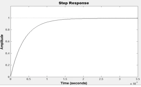
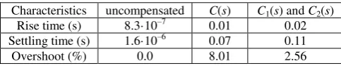
This section presents the simulation results obtained in MATLAB. Figure 6 is simulation results for control loop simulation of the plant (uncompensated). With first feed-back compensator added to the forward path of the closed-loop, simulation was conducted and result ob-tained is shown in Figure 7. Figure 8 is the simulation result of the final proposed closed control system for two-phase hybrid stepping motor with two-compensator con-trol algorithm. Figure 9 is the Bode stability plot of the proposed two-compensator closed loop control. The performance comparison of the system for various simu-lation cases considered is presented in Table 5.
Figure 6 – Step response plot for uncompensated system
Figure 7 – Closed loop step response with compensator C(s)
Journal of Engineering Sciences, Volume 6, Issue 1 (2019), pp. D 1–D 6 D 5
Figure 9 – Bode plot of the final simulation closed-loop system
Table 5 – Characteristics performance comparison
Characteristics uncompensated C(s) C1(s) and C2(s)
Rise time (s) 8.3·10–7 0.01 0.02 Settling time (s) 1.6·10–6 0.07 0.11 Overshoot (%) 0.0 8.01 2.56
5
Discussion
The step response performances of the various cases considered are presented in Table 5. It can be seen that the result of the uncompensated two-phase hybrid step-ping motor control loop shown in Fig. 6 is quite promis-ing. However, the response performance gives 0 % over-shoot and below the setpoint value. This indicates that the
system is sluggish and requires that the response being improved to enhance the setpoint tracking performance. With the first compensator C1(s) added to the forward path of the closed loop control structure, the step re-sponse curve (Figure 7) shows that system characteristics performance is enhanced with a better tracking perfor-mance. However, the system overshoot is higher than the desired overshoot (less than 5 %). In Figure 8, the step response performance of the system is well improved by the proposed compensator control network for two-phase hybrid stepper. A more preferred stable control loop is achieved with better tracking performance than the single loop compensator control system. Figure 9 shows the stability plot of the proposed control loop structure for a two-phase hybrid stepper motor. The plot shows that the system is stable
6
Conclusions
This paper has successfully simulated a two-compensator control loop network for two-phase hybrid stepper motor. Though many control techniques using bang –bang con-trol, conventional PID, Fuzzy-PID, and other form of controllers have been widely implemented in Literature. However, in this paper, a new approach has been pro-posed which combines two-compensator in a two-phase hybrid steeper motor control loop to improve tracking response performance. The result obtained shows that the developed control system meets the required performance criteria in terms of rise time, settling time, and % over-shoot.
References
1. Attiya, A. J., Shneen, S. W., Abbas, B. A., & Wenyu, Y. (2016). Variable Speed Control Using Fuzzy-PID Controller for Two-phase Hybrid Stepping Motor in Robotic Grinding. Indonesian Journal of Electrical Engineering and Computer Science, Vol. 3(1), pp. 102–118, doi: 10.11591/ijeecs.v3.i1.pp102-118.
2. Nagrath, I. J., & Gopal, M. (2005). Control Systems Engineering. 4th Edition, New Age International Publishers.
3. Zhan, R., Wang, X., Yang, Y., & Qiao, D. (2008). Design of two-phase hybrid stepping motor driver with current closed-loop control based on PIC 18F2331. Electrical Machines and Systems, ICEM 2008. International Conference on IEEE.
4. Bellini, A., Concari, C., Franceschini, G., & Toscani, A. (2004). Mixed mode PWM for high performance stepping motors. Con-ference of IEEE Industrial Electronics Society, IECON.
5. Zhaojin, W., Weihai C., Zhiyue, X., & Jianhua, W. (2006). Analysis of Two-Phase Stepper Motor Driver Based on FPGA. IEEE International Conference on Industrial Informatics.
6. Zhang, S., & Wang, X. (2013). Study of Fuzzy-PID Control in MATLAB for Two-phase Hybrid Stepping Motor. Proceeding of the 2nd International Conference on Systems Engineering and Modeling (ICSEM-13), pp. 1011–1014.
7. Melin, P., & Oscar, C. (2005). Intelligent control of a stepping motor drive using an adaptive neuro–fuzzy inference system. In-formation Sciences, Vol. 170(2), pp. 133–151.
8. Wale, J. D., & Pollock, C. (2001). Hybrid stepping motors and drives. Power Engineering Journal, Vol. 15(1), pp. 5–12. 9. Baldha, S., Shukla, J., & Tarpara, K. (2015). Design and Simulation of Two-Phase Hybrid Stepper Motor with Current
Track-ing. National Conference on Emerging Trends in Computer, Electrical & Electronics (ETCEE-2015), International Journal of Advance Engineering and Research Development (IJAERD).
10. Degang, C., & Brad, P. (1993). Adaptive Linearization of Hybrid Step Motors: Stability Analysis. IEEE Transactions on Auto-matic Control, Vol. 38(6), 8pp. 74–887.
D 6 MECHANICAL ENGINEERING: Dynamics and Strength of Machines
12. Salis, V., Chiappinelli, N., Costabeber, A., Zanchetta, P., Bifaretti, S., Tomei, P., Verelli, C. M. (2018). Learning Position Con-trols for Hybrid Step Motors: from Current-fed to Full-Order Models. IEEE Transactions On Industrial Electronics, Vol. 1, 326543.
13. Liu, G. F., & Li, H. W. (2017). Design of stepper motor position control system based on DSP. 2nd International Conference on Machinery, Electronics and Control Simulation, Advance in Engineering Research, Vol. 138, pp. 207–211.
14. Khalilian, M., Abedi, A., & Zadeh, A. D., (2012). Position Control of Hybrid Stepper Motor Using Brain Emotional Controller. Energy Procedia, pp. 1999–2003, doi: 10.1016/j.egypro.2011.12.1200.
Покращення характеристики керування двофазним гібридним кроковим
двигуном із застосуванням PID
-
налаштованих компенсаторів
зовнішнього та внутрішнього контурів
Ониека Е. Б.1, Чід’єбере М.2, Нкірука А. П.2 1 Кафедра електроніки, Університет Нігерії, м. Ншукка, Нігерія;
2 Кафедра електротехніки та електроніки, Університет Ч. О. Оджуку, м. Улі, Нігерія
Анотація. У статті наведено поліпшену характеристику керування двофазним гібридним кроковим двигуном із використанням PID-налаштованих компенсаторів зовнішнього та внутрішнього контурів.
Підвищено ефективність відгуку двофазного гібридного крокового двигуна до досягнутого пере регулювання нижче 5% і часу регулювання 0,16 с. Для досягнення мети дослідження створено динамічну модель
двофазного гібридного крокового двигуна за допомогою передаточної функції. Обрано надійну методику PID-налаштування, яка використовує єдиний вхідний сигнал із застосуванням графічного інтерфейсу
користувача, а також диспетчера інструментів контролю та оцінки програми MATLAB для проектування
компенсаторів. Для підвищення ефективності відгуку один компенсатор спроектовано і вбудовано до
керуючого контуру двофазного гібридного крокового двигуна. Числове моделювання виконувалось у
програмі MATLAB, а коефіцієнт перерегулювання становив 8 % для одноланкового компенсатора. Однак
наявне перерегулювання системи вимагає подальшого її удосконалення. У зв’язку із цим, було
запропоновано новий контур керування із використанням структури з двокомпенсаторним контуром. У
результаті розроблено компенсатори зовнішнього і внутрішнього контуру, які застосовані при керуванні двофазним гібридним кроковим двигуном. Числове моделювання здійснювалось із застосуванням MATLAB,
а отриманий результат показав, що для двокомпенсаторної структури перерегулювання було значно скорочено до 2,6 % з часом регулювання 12 мс. Цей результат свідчить про покращення ефективності
системи відстеження відгуками шляхом застосування комбінованих зовнішніх і внутрішніх контурів компенсаторів.
Ключові слова: компенсатор, контур керування, графічний інтерфейс користувача, пропорційні інтеграл і
![Figure 1 – General stepping motor with its main parts[1, 7]](https://thumb-us.123doks.com/thumbv2/123dok_us/1281489.1634445/2.595.324.516.74.187/figure-general-stepping-motor-main-parts.webp)
![Table 1 –Simulation parameters [8]](https://thumb-us.123doks.com/thumbv2/123dok_us/1281489.1634445/3.595.313.538.108.396/table-simulation-parameters.webp)