2nd International Conference on Current Research Trends in Engineering and Technology © 2018 IJSRSET | Volume 4 | Issue 5 | Print ISSN: 2395-1990 | Online ISSN : 2394-4099 Themed Section: Engineering and Technology
A Review on Failures of Leaf Spring in Automobile
Patel Meet G.
1, Patel Krunal R.
2, Vahora Anish
3, Chaudhari Viren
4,
Mr. Nirav Saksena
51-4U.G. Student, Mechanical Engineering, Sigma Institute of Engineering, Vadodara, Gujarat, India 5Assistant Professor, Mechanical Engineering, Sigma Institute of Engineering, Vadodara, Gujarat, India
ABSTRACT
The plan of leaf spring has been a steady test for car and assembling designers and it has experienced numerous modifications. Leaf springs are one of the mainstream suspension parts they are much of the time utilized. This paper writing has shown a more enthusiasm for the supplanting of steel spring with composite leaf spring. The assurance of the purpose of disappointment amid a mishap arrangement of a back leaf spring in a game utility vehicle is displayed as far as break surface examination and leftover quality appraisals. Broad woody break and auxiliary splitting at the midplane of the spring was confirmed for isolation and shortcoming in the spring.
Keywords: Leaf spring failure, fracture mechanism, failure modes, composites, failure analysis, woody fracture
I.
INTRODUCTIONRecognizable proof of the point in time that a break happens can be urgent in the reproduction of a mischance, especially those including vehicles. Proof to recognize the point in time of the disappointment can be found in various structures
The disappointment investigation displayed in this paper influenced utilization of confirmation for break to surface tainting, abnormal crack morphology, stretch examination, and crack mechanics to distinguish the point in time in a mischance succession of a car leaf spring disappointment. The leaf spring can either be appended straightforwardly to the edge at the two closures or joined toward one side, more often than not the front, with the opposite end connected through a shackle, a short swinging arm.
The shackle takes up the inclination of the leaf spring to lengthen when compacted and in this way makes
for milder springiness. Disappointment of mechanical get together part is a typical wonder because of break that happens wherever in mechanical structures. The fundamental driver of disappointment of leaf spring is because of extensive bowing conduct.
In vehicle leaf spring is one of the pivotal parts for weight lessening as it represents 15% - 20% of unsprung weight. Composite materials have made it conceivable to decrease the heaviness of leaf springs with no diminishment in stack conveying limit and solidness.
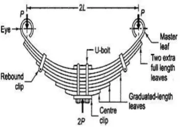
Figure-1: Main parts of Leaf Spring(3)
This figure demonstrates a covered semi-elliptic spring. The best leaf is known as ace leaf. The eye is accommodate appending the spring with another machine individuals. The measure of curve that is given to the springs from the focal line, going through the eyes, are known as camber. The camber is given so that even at the greatest load the avoided spring not touch the machine part to which it is connected. The focal clasp is require to get the leaves of the spring.
II.
METHODS AND MATERIALE. Mahdi a, O.M.S. Alkoles etc presented work on light composite elliptic springs for vehicle suspension. They worked on based study marries between the elliptical configuration and woven roving composites. In this paper, the influence of ellipticity ratios on performance of woven roving wrapped composites elliptical springs has been investigated both experimentally and numerically.
Y. N. V. Santhosh Kumar, M. Vimal Teja etc presented work on design and analysis of composite leaf spring . They also discussed that the advantages of composite materials like higher specific stiffness and strength, higher strength to weight ratio. This work deals with replacement of conventional steel leaf spring with a Mono Composites leaf spring using E-Glass/Epoxy.
M.M.Shokrieh and D.Rezaei presented work on design, analysis and optimization of leaf spring. The aim of this review paper was steel leaf spring was replaced with an optimized composite one. Main objective of this paper was to obtain a spring with minimum weight that is capable of carrying given
H.A.AI-Qureshi studied on automobile leaf spring from composite materials. The aim of this paper is design, analysis & fabrication of composite spring. For this compact car is taken as prototype. A single leaf, variable thickness spring of glass fiber reinforced plastic with similar mechanicals and geometrical properties to the multileaf steel spring was designed, fabricated and tested.
Malaga. Anil Kuma, T. N. Charyulu, etc presented work on design optimization of leaf spring. The automobile industry has shown increase interest in the replacement of steel springs with composite leaf spring.
Break of the spring happened at the framed forward eye, as appeared in Fig. 2. Correlation of the eye with unbroken springs uncovered that it had to some degree unwrapped before the disappointment. The position of the two softened winds up Fig. 2 overstates the earlier twisting. Striking highlights of the break were the nearness of broad optional splitting at the midplane, the ventured idea of the crack, and "woody break" on the ventured surface parallel to the spring surface.
Fig. 2 The broken halves of the spring have been placed together in a manner exaggerating the opening
of the eye before rupture(3)
Fig. 3 The spring half of the fracture has deep secondary cracking along the midplane(3)
Figure 4 demonstrates a delegate region of crack roughly somewhere between within surface of the spring eye and the midplane break. This break surface is opposite to the long hub of the spring. Break surfaces were cut from the springs for simpler tiny examination and for metallography. This accommodated a more total examination than was workable for the mishap spring.
Fig. 4 This fracture area is approximately halfway between the inside spring surface and the midplane
fracture(3)
The leaf spring was secured straightforwardly to the vehicle outline at the forward end and through a shackle get together at the toward the back end. This course of action is appeared in Fig. 5.
An elastic grommet with a steel external sleeve and an inward steel jolt sleeve, both clung to the elastic, was put in each eye so the get together would not slip. The jolt sleeve closes were serrated with the goal that they would not pivot against the edge.
Fig. 5 Reaction forces on the spring eyes in the vehicle are complex(3)
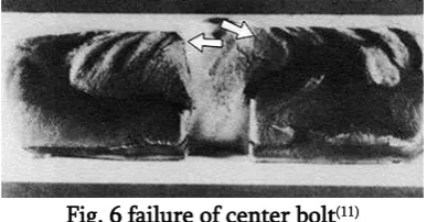
The image shows center bolt failure due to a truck spring not having tight enough u-bolts. U-bolts especially on newly installed truck springs should be checked periodically to verify they are tight. Even if you have a professional installer install springs on your truck, you should stop by after 500 miles and have your u-bolts inspected to make sure they didn't come loose.
Fig. 6 failure of center bolt(11)
Corrosion and fatigue are typically caused by a combination of time and the elements. Numerous variables will weigh on how long your leaf spring will last before it suffers from corrosion or fatigue. How much weight you haul, what part of the country you live in, etc. will play a role in the life of your springs. Making sure salt and other corrosive materials are washed off and not overloading your truck will help prevent corrosion and early spring fatigue.
III.
RESULTS AND DISCUSSION Leaf Spring Failure Analysis :-Once the spring life limit is reached a fatigue failure will or has occurred.
Shock Absorbers:
A properly functioning shock absorber will tend to reduce the spring deflection as the vehicle hits a bump. Lower spring deflections mean lower operating stresses on the spring which in turn gives longer fatigue life. This is especially true for full taper springs which do not have the high interleaf friction to help dampen spring deflections. Worn or missing shock absorbers must be replaced to maximize spring life.
Brake Adjustments:
Improperly adjusted brakes can also reduce spring life. Under braking, springs are expected to absorb some of the braking forces. If the brakes on an axle are unevenly adjusted one spring will have to absorb more than its share of braking force which can reduce its fatigue life.
Protective Coatings:
Corrosion is one of the major factors in reducing spring life. Proper paints and care during handling and installation can help to slow the spread of spring corrosion. On full taper springs the only acceptable coating is the individual painting of each leaf with zinc-rich paint. This paint may be recognized by its characteristic gray color.
Surface Condition:
The condition of the spring surface also has an effect on fatigue life. Generally, a fatigue crack will start at some sort of surface defect on the spring leaf. Therefore, care needs to be used when manufacturing and installing springs to reduce these defects to a minimum.
Shot Peening:
Extensive testing indicates that shot peening can increase the life of springs by a factor of three or more. It is not enough, however, to simply shot peen the first one or two leaves in an assembly-all leaves must be shot peened. All major vehicle manufacturers specify that their OEM springs have each leaf shot peened.
Discussion :-
There was extensive confirmation that the spring was split for quite a while before the mischance:
A critical nearness of chlorine and calcium (alongside different components) was found in the OD split and the midplane break. Chlorine, specifically, must be clarified by earlier go on a maritime ship.
Rubbing harm was watched locally on the midplane crack.
Area of the break of the spring toward the beginning of the loss of control is predictable with other proof in the mishap. Wheel clean stamps in both wheel wells are reliable with a moving tire. Break of the spring in a stone strike would deliver not as much as a fourth of an upset, in light of the fact that the drive would be on the request of milliseconds.
This was not predictable with marks in the left back wheel well. An arrangement of imprints in the street ahead of schedule in the loss of control was related to the sponsorship plate, therefore finding the hub disappointment right on time in the grouping. In view of this arrangement, the spring disappointment probably went before the hub disappointment.
From above result it is clearly seen that the objective was to obtain a spring with minimum weight. For this the steel leaf spring is replaced by composite leaf spring. This is better than using steel leaf spring.
Following are the different types of failure in automobile leaf spring:
Loose U-Bolts:-The center bolt failure due to a truck spring not having tight enough u-bolts.
Corrosion and failure:-Corrosion and failure are typically caused by a combination of time and the elements.
Overloading your truck spring:-Overloading is pretty self explanatory.
Weld splatter:-This is caused by welding a body or accessories to your truck in the same area as your leaf spring.
V.
REFERENCES[1].
Mahmood M. Shokrieh, Davood Rezaei “Analysis and optimization of a composite leaf spring” Composite Structures, 60 (2003) 317– 325[2].
E. Mahdi a, O.M.S. Alkoles a, A.M.S. Hamouda b, B.B. Sahari b, R. Yonus c, G. Goudah“Light composite elliptic springs for vehicle suspension ” Composite Structures, 75 (2006) 24–28[3].
C.K. Clarke and G.E. Borowski Evaluation of a Leaf Spring Failure Submitted July 18, 2005; in revised form August 31, 2005)[4].
Yogesh Nikam, Dr.Avinash Badadhe design analysis and failure modes of leaf spring in suspension system, International Research Journal of Engineering and Technology (IRJET)[5].
Manas Patnaik, Narendra Yadav, Ritesh Dewangan“ Study of a Parabolic Leaf Spring by Finite Element Method & Design of Experiments ”International Journal of ModernEngineering ResearchVol.2, Issue 4, July-Aug 2012 pp-1920-1922.