Page | 7
Analysis and Design of Four Leg Steel
Transmission Tower using Staad. Pro
Heera Lal Bhardwaj
1,Ajit
2, Yogesh Kaushik
31
Student, MTECH Civil, CBS Jhajjar Haryana, India
2Assistant Professor, Civil, CBS Jhajjar, Haryana, India 3Assistant Professor, Civil, Amity University, Noida, India
Abstract—
In this project, the design of steel lattice tower prescribed for transmission of electricity by the categorized gravity and lateral loads has been studied and analysed for the employment of the project. The analysis has been done by taking different combination of loads and then the design has been come into picture using the code module IS 800:1984.The present work describes the analysis and design of transmission line tower of 25 meter height viz. various parameters. In design of tower for weight optimization some parameters are considered such as; base width, height of tower , outline of tower. Using STAAD , analysis of transmission towers has been carried out as a 3-D structure. The tower members are designed as angle section.Prior to the design process the convincing site investigation and Envoirmental impact assessment data has to to collected through various modes via Electronic or Print media. The desired safety factors has been actuated contemplating the selected location i.e Kasouli. The various factors including envoirmental and materials used for the structure is also be considered.The foundation detailing is chosen keeping in consideration the geotechnical investigation data. The software tool used in the process is STAAD.Pro 2008. The load calculations were performed manually but the analysis and design results were obtained through STAAD.Pro 2008. At all stages, the effort is to provide optimally safe design along with keeping the economic considerations.
Keywords—Transmission Tower, STAAD.Pro 2008, Non-linear irregularities.
I. INTRODUCTION
The objective of this project is to propose a steel lattice tower for electricity transmission system and analyze it under various loads thereby designing and checking the proposed members for failures. The tower is to be located in the city of Kasouli , Himachal Pradesh. Safe and economic design of steel transmission tower using the software tool STAAD.pro 2008. The height of the tower is 25 m. The number of cables supported by this tower is 7.
Staad-Designed Transmission Tower Example
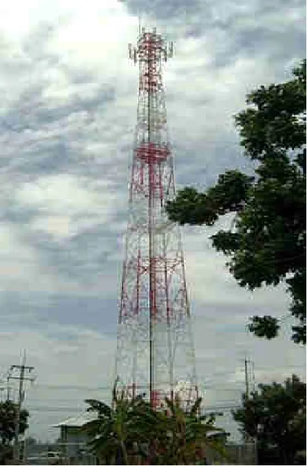
Figure 1.1 shows Wattana Transmission Tower. Somedetails are as follows:
Location: Outside of Bangkok, Thailand Designed by: PBP Steel Co., Ltd.
Managing Director: Capt Nattapong Buapli Rtn. Senior Engineering Consultant: Mr. Sompoch Tiangwan Software Tool Used: STAAD.Pro
Fig. 1.1: Wattana Transmission Tower
II. DETAILS OF TOWER
In the present section, the tower has been detailed for its location, type and kind of constituent members.
Introduction to Tower
Page | 8 and maximum width. A tower is a freely standing self
supporting structure fixed to the base or foundation.
In developed countries the environmental impact of the traditional transmission towers is no longer accepted. Currently available design solutions with acceptable appearance are not employed in the developing countries, mainly for cost reasons. In the developing countries the use of the traditional lattice transmission towers will continue employing steel angles. A comparison of the available design specifications for steel angles in transmission towers is presented.
Generally towers are made up of a material called steel. Steel towers (short, medium and tall) are normally used for the following purposes:
(i) Electric power transmission
(ii) Microwave transmission for communication
(iii) Radio transmission (short and medium wave
wireless)
(iv) Television transmission
(v) Satellite reception
(vi) Air traffic control
(vii) Flood light stand
(viii)Metrological measurements
(ix) Derrick and crawler cranes
(x) Oil drilling masts
(xi) Over head tanks
Further classification of towers depending upon their heights is as follows:
The height of towers for electric power transmission may vary from 10 to 45m while those for flood lights in stadiums and large flyover intersections may vary from 15 to 50m. The height of television towers may vary from 100 m to 300 m while for those for radio transmission and communication networks the height may vary from 50 to 200m.
Depending upon the size and type of loading, towers are grouped into two heads:
(a) Towers with large vertical loads
(b) Towers with mainly horizontal wind loads
Towers with large vertical loads (such as those of over head water tanks, oil tanks, metrological instrumentation towers etc.) have their sides made up of vertical or inclined trusses. The towers, falling under the second category and subjected predominantly to wind loads, may be classified in to two types:
(1) Self-supporting towers
(2) Guyed towers
(1) Self-supporting towers
Self-supporting towers or free standing towers are known as lattice towers. These are generally square in plan and are supported by four legs, fixed to the base.
These towers act as vertical cantilever trusses, subjected to wind and/or seismic loads. Free standing towers are
commonly used for T.V., microwave transmission, power transmission, flood light holding.The free standing towers for power transmission have arms to both the sides of the centre line, to carry power transmission lines.
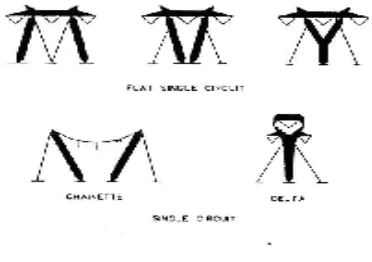
Fig. 1.2: Self Supporting Towers
III. GUYED TOWERS
Guyed towers are hinged to the base, and are supported by guy wires attached to it at various levels, to transmit the wind forces to the ground. Due to this reason, guyed tower of the same height is much lighter than a self- supporting tower.
However, it requires much larger space in plan, to accommodate the placement of guy ropes. Guyed towers are mostly known as masts, having three or four legs and triangular or rectangular configuration in plan.
Fig. 1.3: Guyed Tower 3.1.2 Lattice tower
Page | 9 The top width of towers is kept between 1.5 to 3m or more,
depending upon the requirement.
There are ten types of bracing systems for a lattice tower configuration. Those ten types are as follows:
1.Single diagonal bracings: This is the simplest form of bracing. The wind shear at any level is shared by the single diagonal of the panel. Such bracing is used for towers upto 30m height.
2.X-X bracing: This is a double diagonal system without horizontal bracing, used for towers upto 50m height. It is a statically determinate structure.
3. X-B bracing: This is a double diagonal system with horizontal bracings. Such bracings are quite rigid, and may be used for towers up to 50m height. The structure is statically indeterminate. The horizontal members are redundant members and carry only nominal stresses.
4. K-bracing: such a bracing gives large head room, and hence K-bracing can be used in lower panels where large head room is required. The structure is statically determinate. Such bracing can be used for towers of 50 to 200m height. In most of the transmission line towers, the lower panels is either K- or Y- braced and upper panels are X-braced or XB- braced.
5. X B X bracing: This is a combination XX and XB bracing where horizontal members are provided only at the level of crossing of diagonals. The structure is statically indeterminate. However, the length of the diagonal is reduced. The system is suitable for towers 50 to 200m height. 6. W-bracing: This system uses a number of overlapping diagonals. The system is statically indeterminate. However, the effective length of diagonals is reduced the system is quite rigid and may be used for towers of 50 to 20m height. 7.Y-bracing: This system gives larger head room can be used for lower panels. The system is statically determinate. In most of the transmission line towers, lower panels are either Y-braced on k-braced and upper panels are X-B braced or X-braced.
8.Arch bracing:Ssuch a bracing can be adopted for wider panels. This system also provides greater head room. The system is statically determinate.
9.Subdivided V-bracing: Such a bracing are used for tall towers of communication systems, radio and TV transmission etc; for heights between 50 to 200m.
10.Diamond lattice system: A typical diamond lattice system is used for towers of 100 to 200m height. The base width is kept at 1/5 to 1/6 of the height. Rigid horizontal diaphragms are used at top and at intermediate sections, preferably at intervals of 25 to 30m, to increase the torsion stiffness of the cross-section.
Components of the tower 1. Cables
2. Rolled Steel long leg unequal angles back to back
3. Rolled Steel long leg equal angles back to back 4.Concrete Base
5.Footing
Parameters of the tower
1. The building lies in Seismic Zone IV 2. The factor of safety of the tower is 1.2 3. The height of the tower is 25.25m. 4. The base width of the tower is 3.52m. 5. The top width of the tower is 1.52m. 6. The Flange width in the tower is 2.7m.
7 . The bearing capacity of the soil assumed to be 250 kN/m2.
Analysis model for tower
Number of members: 492
Number of joints: 151
Loading: Self weight, Wind load,
Cable load
Analysis: Using STAAD.Pro
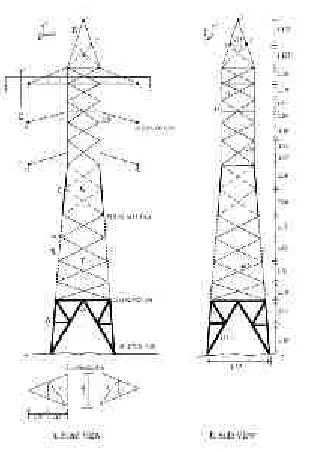
Page | 10 Fig. 1.5:Front view and side view of TransmissionTower
Estimation of Loads for Analysis and Design
For the Transmission tower, analysis was performed and the design done for the following loads:
1.Self Weight 2.Wind load and 3.Cable load Self Weight
The self weight is precisely considered as the dead load of the structure as these loads neither change their position nor do they vary their magnitude. Actually, according to IS 1911:1967, the density of steel is 7850 kg/m3 but we have assumed the self weight of both super and substructure of the tower as 1 kN/m2 in downward direction.
Wind load
The term wind denotes almost exclusively to horizontal wind. Wind pressure, therefore, acts horizontally on the exposed surfaces of towers.
Here, we have followed Design wind speed as per IS: 875-1987. The design wind speed (Vz) is obtained by multiplying the basic wind speed (Vb) by the factors k1,k2andk3
Vz =Vb×k1×k2 ×k3 Where,
Vb = the basic wind speed in m/s at 10 m height k1= probability factor (or risk coefficient) k2 = terrain, height and structure size factor k3 = topography factor.
The basic wind speed of Kasouli is taken as 39 m/s as per IS-875:1987 Part-III.
Probability factor (or risk coefficient)k1
The factor k1is based on statistical concept which take account of degree of reliability required a period of time in
years during which there will be exposure to wind. In actual practice the factor k1depends on type and importance of structure, design life of structure and basic wind speed in the region.
Table 1:Values for factor k1
Terrain, height and structure size factor k2
This factor takes into account terrain roughness, height and size of structure for determining k2. Terrains are classified in to four categories and structures according to their heights into three classes.
Categories of structure
There are mainly four categories of structure for terrain, height and structure size which are as follows:
Category 1:
This represents exposed open terrain with few or no obstructions i.e. open sea coasts and flat treeless plains. Category 2:
This represents open terrain with well scattered obstructions having height between 1.5 to 10 m., i.e. air fields, under developed built-up outskirts of towns and suburbs.
Category 3:
This represents terrain with numerous closely spaced obstructions. This category includes well wooded areas, shrubs, towns and industrial areas fully or partially developed.
Category 4:
This represents terrain with numerous large high closely spaced obstructions above 25m., i.e. large city centres. Classes of structure
There are mainly three Classes of structure are as follows: Class A: Structures having maximum dimension less than 20m.
Class B: Structures having maximum dimension between 20 to 50m.
Value of factor k1
Class of
structure
Mean design life
Factor for basic design wind speed
33 39 44 7 50
All Buildings
50 1.0 1.0 1.0 1.0 1.0
Temporary sheds
5 0.82 0.76 0.73 0.71 0.70
Structure showing low degree hazard
25 0.94 0.92 0.91 0.90 0.90
Important Structures like
hospitals etc
Page | 11 Class C: Structures having maximum dimension greater than
50m.
IV. ANALYSIS OF TOWER
Data Input for Analysis with STAAD.pro
STAAD.pro requires data input in some form like graphical or text. The following data was fed to STAAD.pro
graphically:
1.Member lengths and locations 2.Mutual Connectivity of members 3.Supports
4.Assigning type and properties of members 5.Assignment of loads due to wind and cables 6.Grouping of members
Following data were inserted as text: 1.Load Combinations
2.Load List for Analysis
3.Desired analysis results like Nodal displacements, Support reactions etc.
Summary of Member End Forces
The following table has been obtained from STAAD.pro results. It is obvious that the load cases containing Wind Load in Z direction are most critical.
Table: Summary of Member Forces Bea
m L C
Node Fx Fy Fz
Ma x Fx
198 9
2 3408.19
2 -21.35 8 -3.827 Mi n Fx 9 9 9 -3185.50 5 -12.36 6 3.644 Ma x Fy 3 9
5
-527.761 22.05 -8.13
Mi n Fy
2 9
5
-533.144
-22.32 7.696
Ma x Fz
218 9
78 -68.797 0.716 40.75
4 Mi n Fz 220 9
78 -58.811 1.091 42.13
5 Ma x Mx 8 9
8 199.356
-7.982 4.382
Mi n Mx
5 9
9 207.204
-6.159 -4.971
Ma 204 9 85 180.207 -
-x My 20.67 3 21.72 5 Mi n My 204 9
1 180.998
-21.00 5 -21.72 5 Ma x Mz 197 9
1 3251.43
1
-20.85 3.491
Mi n Mz
204 9
85 180.207
-20.67 3 -21.72 5
Table: Summary of Member Forces
Mx My Mz
Max Fx -0.051 -4.671 23.157
Min Fx 0.05 -4.772 -8.188
Max Fy 0.016 5.769 20.552
Min Fy -0.029 5.014 20.984
Max Fz 0.057 -20.732 -3.614
Min Fz -0.045 20.879 -2.505
Max Mx 0.109 -1.838 -6.22
Min Mx -0.103 2.583 -5.243
Max My 0.009 25.864 -24.64
Min My 0.009 -24.196 23.378
Max Mz 0.048 4.437 23.955
Min Mz 0.009 25.864 -24.64
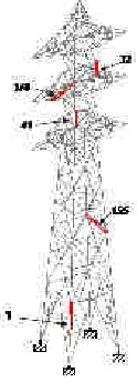
shows the representative members whose axial and shear forces diagrams were plotted by STAAD.pro and shown in figures 4.4 to 4.8.
Page | 12 Fig 1.7: Variation of axial forces of member no.1
Fig 1.8 Variation of axial forces of member no.376
Fig 1.9: Variation of axial forces of member no.41
V. DESIGN METHODOLOGY
The design of steel transmission tower is done in phases. The first phase consisted of accumulating and organizing soil investigation and geotechnical data, environmental data i.e. wind speed, topography and terrain factors. The second phase consisted of performing design calculations to make the structure compatible to various forces and loads. After then the tower was designed using STAAD.pro 2005. Then the tower was analyzed for being compatible with various loads. Ultimately the tower design was considered for optimum safety consideration on most economical cost.
Data Input for Design with STAAD.pro
• Types of sections of all member groups
• ISA Specifications for various anglesacording to
theirexpected design performance.
• Materialrequirements i.e. concrete in base and
substructure, steelin superstructure.
• Loadcombinationswithappropriatefactors as per
IS-875: 1987-V
• Effective lengthfactors for variuosmembers
• Foundation and soilparameters i.e. mositure content
and plasticityetc.
VI. DESIGN RESULTS FOR SUPERSTRUCTURE
The design wasfinallyperformed by STAAD.pro and the resultsobtained are tabulated as below:
Table: Design Results
Ratio Ay
(cm2) Beam Az (cm2)
Ax (cm2)
Dw (cm)
Bf (cm)
0.141 14.4 1 14.4 40.38 9 9
0.192 10.667 2 10.667 30.1 8 8
0.035 14.4 3 14.4 40.38 9 9
0.037 14.4 4 14.4 40.38 9 9
0.025 14.4 5 14.4 40.38 9 9
0.042 12 6 12 34.06 9 9
0.02 9.333 7 9.333 26.04 7 7
0.038 12 8 12 34.06 9 9
0.049 12 9 12 34.06 9 9
0.055 12 10 12 34.06 9 9
0.061 12 11 12 34.06 9 9
0.08 12 12 12 34.06 9 9
0.064 12 13 12 34.06 9 9
Table: Design results
Ratio Iz (cm4) Iy (cm4) Ix (cm4)
0.141 300.582 591.753 19.382
0.192 177.969 345.444 10.033
Page | 13
0.037 300.582 591.753 19.382
0.025 300.582 591.753 19.382
0.042 258.363 490.924 11.353
0.02 116.321 232.488 8.68
0.038 258.363 490.924 11.353
0.049 258.363 490.924 11.353
0.055 258.363 490.924 11.353
0.061 258.363 490.924 11.353
0.08 258.363 490.924 11.353
0.064 258.363 490.924 11.353
VII. CONCLUSION
The assimilation of field investigation data is necessary for the accurate planning and faster implimentation of the project. The present project presented the idea for using the advanced structural tool STAAD.pro to solve complicated engineering problems involving beam and nodes with great ease and in very less time.
It has been revealed that the load combinations involving wind-forces were critical amongst all combinations. Hence the design was carried out for those combinations. The wind force normal to cables was found to the worst of all. The design given by STAAD.pro has been found to be complying with IS-800: 1984 and all the members were safe.
No matter how sophisticated the software be, It is always the scheme and the specifications of the human engineer, which has to be fed in to get desired and applicable solutions. Thus, it is necessary that the person using the computer applications must be an expert in his area. Hence forth during our compilation of the project we tried to contain the combination of safe design.
REFERENCES
[1] Y. M. Ghugal , U. S. Salunkhe [1] “Analysis and Design of Three and Four Legged 400KV Steel Transmission Line Towers: Comparative Study” H.O.D. Applied Mechanics Department, Govt. College of Engineering, Aurangabad Maharashtra (India), Post Graduate Student of M.E. (Structural Engineering), Applied Mechanics Department, Govt. College of Engineering, Aurangabad. International Journal of Earth Sciences and Engineering 691 ISSN 0974-5904, Volume 04, No 06 SPL, October 2011, pp 691-694
[2] V. Lakshmi1, A. Rajagopala Rao [2] “EFFECT OF
MEDIUM WIND INTENSITY ON 21M 132kV TRANSMISSION TOWER” Assistant Professor, Civil Engineering, JNT University Kakinada, Andhra Pradesh, India, Professor of Civil Engineering (Retd) JNT University Kakinada, Andhra Pradesh, India, ISSN: 2250–3676 Volume-2, Issue-4, 820 – 824
[3] M.Selvaraj, S.M.Kulkarni, R.Ramesh Babu [3]
“Behavioural Analysis of built up transmission line tower from FRP pultruded sections” Central Power Research Institute, Bangalore, India , National Institute of Technology Karnataka, Mangalore, India ISSN 2250-2459, Volume 2, Issue 9, September 2012.
[4] S.Christian Johnson 1 G.S.Thirugnanam [4]Research
Scholar, Head & Professor in civil Engg. IRTT “Experimental study on corrosion of transmission line tower foundation and its rehabilitation” International Journal of Civil and Structural Engineering ISSN 0976 – 4399 Volume 1, No 1, 2010
[5] F.Albermani and M. Mahendran [5] “Upgrading Of
Transmission Towers Using Of Diaphragm Bracing System” Dept. of Civil Engineering, University of Queensland, Brisbane, Australia School of Civil Engineering, Queensland University of Technology, Brisbane, Australia Dept. of Building and Construction, City University of Hong Kong, Hong Kong .
[6] N.PrasadRao, G.M.Samuel Knight, S.J.Mohan, N.
Lakshmanan [6] “Studies on failure of transmission line
towers in testing” College of Engineering
Gunidy ,Anna University, Chennai 600 025 India, Structural Engineering Research Center, Chennai 600 113,India
[7] G.Visweswara Rao[7] “OPTIMUM DESIGNS FOR