IJSRSET1624106 | Received : 26 July 2016 | Accepted : 01 August 2016 | July-August-2016 [(2)4: 464-480]
© 2016 IJSRSET | Volume 2 | Issue 4 | Print ISSN : 2395-1990 | Online ISSN : 2394-4099 Themed Section: Engineering and Technology
464
Modification of Friction Knots Work Surfaces on the Basis of
Microarc Oxidation Method
Vladimir N. Malyshev
Department of Tribology and Repair Technology of Oil and Gas Equipment, Gubkin Russian State University of Oil and Gas, Moscow, Russian Federation, Russia
ABSTRACT
Microarc oxidation (MAO) method also called as plasma electrolytic oxidation (PEO) has a good proven as a way for strengthening working surfaces of parts operating at the friction in many knots of machines and mechanisms. The coatings formed in the mode of anodic-cathode microarc discharges (MAO-coating) have high hardness, strength and good resistance to wear as a pair with many materials, and with itself also, including the conditions with presence of abrasive particles, due to the content significant share of α-Al2O3 in their composition. These pairs can work either with lubrication or without it.
Nevertheless, there are many friction surfaces for which a low friction coefficient is very important, because they work under low level of lubrication or without it. These conditions are characteristic, for example, for the pair "ball - seating" of shut-off valves (ball valves), and others.
Tribological characteristics of working surfaces, strengthened by MAO, can be significantly improved by subsequent impregnation of coating porous system by the UHMWPE (ultra-high-molecular-weight-polyethylene), which melts and fills in the porous structure of the coating thus improving the contact geometry.
The possibilities of MAO-method can expand also greatly when using the electrolytes-suspensions containing solid particles of different nature which are inserted into the coatings composition within the oxidation process. For wear resistance improving as these solid particles may be used different carbides, oxides, nitrides, borides of metals with different degree of dispersion. Such particles are being built into the crystal lattice of alumina and strengthen the working surface of coating significantly.
Keywords: Anodic-cathode MAO, Friction coefficient, UHMW polyethylene, Wear behavior, Electrolytes-suspensions
I.
INTRODUCTION
Different kinds of technological treatment and new methods for their modifications are used for improvement of surface layer properties and structure. The traditional technological methods stipulating predominantly the improvement of bulk properties materials (thermal, thermo and chemical and other kinds of processing) have already exhausted their possibilities. The direct action methods by concentrated streams of energy on details working surfaces derive more and more wide applying now. In
particular, surface structures realizing a low and stable friction coefficient with high wear resistance are being created.
Department of Russian Academy of Sciences (author Markov G.A.) [1-6], which allows forming on the surface fundamentally new high-quality coatings with high wear resistance and good adhesion to substratum. Due to their unique properties, a combination of high wear resistance, corrosion resistance, and also thermo- and erosion resistance, all the more wide areas of different branches of machine industry find practical use of new coatings.
A distinctive feature of plasma electrolytic oxidation is the participation during coatings formation microarc discharges acting rather effectively on surface, as a result of which the composition and structure of received oxide layers essentially differ and properties considerably enhance, as contrasted to usual anode films. Other positive distinctive features of PEO-process are its environmental friendliness and also absence of necessity of preliminary surface preparation in the beginning of technological chain and applying of refrigerating machinery for deriving concerning thick coatings.
II.
STAGES OF METHOD DEVELOPMENT
In a history of investigations development in the area of microarc or plasma electrolytic oxidation it is possible to mark some basic stages. As a starting-point it is possible to consider the discovery in the past century by Russian scientist N.P. Sluginov, the phenomenon of Galvano luminescence at the electrolysis [7]. The second essential stage of investigations was the detection by German investigators A. Guenterschulze and H. Betz the sparking on the anode at anodizing in the area of heightened voltages and the heightened gas-making which is not being subordinated to the Faraday law. As was established later it is explained by thermal expansion ("by thermolysis") of water in the discharge [8]. This sparking long time was considered as the negative phenomenon which led to formation of less homogeneous and more porous films.
The first time the concept of «valve metal» was introduced by Guenterschulze and Betz. The valve metals were defined such as Al, Nb, Ta, Ti, Zr, Hf, W, Bi, Sb, Be, Mg, U, though in a system ―metal – oxide - electrolyte (МOE)‖ the oxides of all metals practically have the valve effect in some extent.
The following stage of investigations development in this direction were the works of American scientists W. McNeil and L. Gruss on practical use of reactions which are flowing in an anodic spark for synthesis complex oxide coatings from components of substrate and electrolyte and which were published in 50-60-th years [9-13,15,16]. Then also the first patents were obtained: on process of coatings formation by anodic-spark processing on magnesium in electrolytes containing anions OH-, PO4
3-, F-, AlO2
-, MnO4
[12]; on treatment process of magnesium and aluminum in ammoniac solutions containing anions Cr2O42, HPO42-,
F- [13,14]; on deriving of silicate coatings on aluminum in weak alkali solutions containing 10-15 % Na2SiO3 or K2SiO3 and 3 % (NH4)6Mo7O24 at voltage U
= 300 V [15]; on deriving process of hard coatings with high bond strength on different metals (Al, Zn, Bi, Ti, Ni, Fe, Mo etc.) in electrolytes containing NaAlO2,
Na2WO4∙2H2O or Na2SiO3∙9H2O [16]. The complex
oxides and other compounds are being formed at such spark mode anodizing, due to high-temperature decomposition of components of an electrolyte in the discharge and their subsequent reactions with anode oxides of substrate metal.
scientific-applied character, theoretical developments on the mechanism of MAO-process while obviously insufficiently, even a uniform terminology was not developed. As a whole, the amount of works continues to grow; some monographs on this problem is published [54,32] that speaks about active method development.
It should be said that in the technical literature for a long time already is debated the question of the method‘s name. As already mentioned above, it is called either microarc oxidation or microplasma method or plasma electrolytic oxidation. Of course, if we will consider the method in terms of its differences from conventional anodizing, then the presence of discharges on the surface during processing should be considered as the main hallmark of this method. From these positions the name of the method as plasma electrolytic oxidation is quite justified. On the other hand, the action of the spark discharges on the surface of material distinguishes from the action of microarc discharges and even more from the action of arc discharges on discharges energy and on quality of the formed coatings. In this regard, the coatings formed under conditions of microarc discharges are the best in terms of quality (high values of physical and mechanical characteristics, hardness, wear resistance, etc.), and therefore the method‘s name as microarc oxidation is the most appropriate.
III.
BASIC MODERN VIEWS ABOUT MAO
MECHANISM
Under the term microarc oxidation many authors [17,20,40,52] understand, as the rule, an electrochemical oxidation on the anode (detail) at the voltages over than sparking voltage, though the sparking process itself (see Figure 1) occupies a rather considerable proportion on the forming curve and stands, thereby, as independent area of study [28, 44].
The complex of initial and boundary conditions of electrochemical process detected by Markov G.A. [19-25], in which one after spark discharges appear the discharges forming a qualitatively new coatings with high protective characteristics - microarc discharges, and several later - arc discharges, has caused in the same time a stimulus for active investigations in the sparking area, especially in the practical plan [27-29,44,54]. The curve of voltage rises within a time at
the fixed total current (Fig. 1) and reflects changing of conductivity of the chain that contains the information about velocity of all chemical reactions happening on an electrode.
Figure 1: Stylistic curve with characteristic formation stages
On the stage of usual anodizing we have a direct contact of electrolyte solution with thin dielectric film on surface in which one arises a high electric field strength providing the ionic conductivity in a film and flowing of oxide processes that are being attended in magnification of its thickness.
The sparks appear at the defined film thickness (for aluminum it is 0.5 - 1 μm) with the flow of two processes simultaneously: an electrochemical oxidation and destruction by sparks of the formed film [8,44]. At the small thicknesses of film only the spark discharges are being watched. The microarc discharges in these conditions do not arise yet for the reason that the main heat rejection into metal does not allow to warm up the film for receiving such conductivity which one is indispensable for appearance of microarc discharges.
At some thickness (for aluminum - more than 2 μm) the heat removal from a film diminishes and spark discharges are being transformed into microarc discharges. In difference from sparks the microarc discharges lead to growth of new quality coating. The process of its formation is being prolonged in all interval of voltage up to limited voltage (Ulimit on the Fig. 1) of microarc oxidation.
complex of different processes, general sign of which ones is the presence of high-temperature chemical transformations and transport of matter in an arc of electric discharge between electrodes with ionic or electronic conductivity. This includes an usual electrolysis, transport of electrolyte (or suspension) matter to electric discharge from solution, high-temperature chemical reactions in electric discharge and neighboring zones including or without participation of electrodes matter that leads to formation on their surfaces the solid (coating) and/or gaseous products [6]. The defined role here, besides of electrochemical processes are played diffusion, chemical, plasma chemical and electro physical processes on the different stages of process. In authors‘ opinion [6] the temperature gradient directed from metal surface to the side of discharge. The heated channel of coating becomes an ionic conductor of a current. The electrolyte and oxide in this place do not contact immediately. The interaction is carried out through the discharge also having an ionic conductivity, i.e. is being created and works the system ―electrolyte - arc (discharge) - oxide - metal‖ that have an ionic conductivity from cathode surface up to anode metal. It is supposed that an indispensable condition of electric discharge arising in electrolyte is the presence of gas or steam-gaseous interlayer between the electrolyte and basis metal [52]. The discharge at the MAO conditions probably is a gas discharge and arises as result an electrical breakdown of steam-gaseous ―corks‖ formed in micro pores of a porous oxide layer growing on a barrier layer. These corks are being formed at the electrolysis processes of ions H+ and/or OH- discharges and boiling of an electrolyte in pores channels. Thus, the basic heterogeneous reactions go between ionized gas - plasma on the one hand, also between material of walls and bottom of micro pores and electrolyte, on the other hand. In the electric discharge act the regularities that are characteristic for anodizing in gas-plasma and plasma electrolytic anodizing.
In electrolytes which are not containing the elements capable to form insoluble oxides, the coating is being formed at the expense of material oxidation. It is electrolytes on the basis of concentrated sulfuric acid, or weak alkali solutions on the basis KOH, NaOH.
If in an electrolyte there are cations or anions containing the elements capable to form insoluble oxides they enter into composition of coating. The
correlation of these oxides with oxides of substrate metal depends on their concentration in an electrolyte. The hydrolysis of electrolyte components with the subsequent thermolysis of hydrolysis products in a zone of the discharge is possible both for cations and anions.
Microarc oxidation for each real combination of metal and electrolyte is being carried out in defined range of voltage and current values. At the reaching some limiting value of voltage (see Fig. 1) the microarc discharges are being replaced by arc discharges. It is being registered visually by sharp change of quality and number of discharges (their amount are being diminished, changed the luminosity, the sizes and the character of their migration on the surface) and at once is being reflected on the curve of voltage rise - the angle of curve varies.
The arc discharges (AD) differ from microarc discharges (MAD) by current intervals. So, if the current of separate MAD is 1 - 30 mА [6], the current of AD is being changed within 30 - 600 mА. Moreover, for each real combination of metal and electrolyte and other fixed parameters there is a defined critical significance of separate discharge current when it can be classified as microarc discharge. According to different outcomes [18,52,54] some characteristics of single micro discharges at MAO-process can lie in a range:
- Temperature 2000-8000 K; Current - 1-70 mА;
Life time - 10-170 μs; Power 0.2-400 W;
Density of discharges ~105 cm-2 ; Current density - 1-28 кА/cm2 ; Dispersed energy ~7∙10-4
Cal (5000 kCal/Mol).
IV.
VARIETIES OF PLASMA ELECTROLYTIC
OXIDATION METHODS AND THEIR
ENERGY CHARACTERISTICS
It should be marked one more variety of materials treatment in modes of microarc and arc discharges burning – the microarc and arc electrophoresis [5,55]. These are processes in which ones the essential moment is the electrophoretic transportation of macroscopic particles weighted in an electrolyte and transformations happening with suspension in a system ―electrolyte - discharge - coating‖. For deriving an electrophoretic effect are used the solutions of electrolytes in which ones the formation of coating in MAD and AD modes are possible and powders of oxides, carbides, borides of metals are entered. Classic electrophoresis [55] in such solutions is not watched, but at the occurrence of MAD begins the sedimentation of powder material entered into electrolyte on an electrode surface. Therefore, an essential role of the discharge in this process is indisputable. The thickness of coating is enlarged, as well as at usual MAO, in accordance with growth of voltage at a stationary value of current density. After reaching some significance of voltage the MAD are being replaced by AD and the electrophoresis is continued in an arc mode, in which one the output of coating matter in some times higher than at electrophoresis in a microarc mode.
The mentioned above processes allow forming coatings on an anode surface and can be used as decorative, corrosion resistant, heat-proof and insulation coatings. The coatings answering to high requests of wear resistance in these modes is rather difficult to receive without engaging of special means, because of relative high porosity and poor coating adhesion to basis.
The substantial possibility of deriving low porous coatings with high adhesion has arisen only after detection by G.A. Markov [23] the phenomenon of formation oxide-hydroxide coatings in conditions of cathode polarization of an electrode. For deriving this effect it is necessary to deposit previously on electrode thin and low porous coating and to set a defined current density. In neighborhoods of pores [6] and then on all surface under a provisional coating begins the formation of oxide-hydroxide layer, which ones differs
from anode coating by their properties [23]. In particular, it is not unipolar, i.e. has high resistivity both at positive and at negative polarity. Due to growth of resistance, the voltage on a bath in Galvano static mode begins to be increased and at reaching a defined magnitude are being formed first microarc and then the arc discharges. The current characteristics of these discharges exceed the relevant maximum characteristics of anodic discharges in 5 - 10 times and approximately correspond to parameters of the discharges formed between two metal electrodes with electronic conduction.
However, as have shown further investigations, the growth of the cathode discharges, unlike from anodic ones, in most cases without organization of special conditions does not lead to formation of quality coatings with high adhesion and toughness. As hindrance, in particular, are the boil of an electrolyte and even the ejection of matter in a zone of the discharge [6]. To organize such process it is indispensable the selection of electrolytes containing any ions or particles of matter which ones could be deposited on a surface of the cathode in conditions of the discharge. Comparison of discharges characteristics between metal electrodes with characteristics of discharges on cathode [50] and also that microarc discharges are not capable to form coating on the cathode without making defined special conditions, have allowed to put forward the supposition that basic in them is the share of electronic carriers of current.
Thus, by Prof. Markov G.A.[5,20,23] was found the second path of discharges organization having a major power in comparison with microarc discharges on the anode, and capable to melt coating up to a vitreous state. These outcomes closely have approximated to the occurrence and realization of idea of an anodic-cathode method – combination of two processes - microarc anodizing and cathodizing and mating of these processes on one electrode.
– 1.5 at alternating positive and negative impulses [56,57].
The analysis of coatings received by this method has shown that they consist from three layers: upper friable, porous, relative soft layer, then internal - dense, with high adhesion, toughness and practically nonporous layer and very thin barrier layer. The presence of two discharges types coexisted simultaneously on one electrode allows to conduct complex electrochemical processes and to change modes of coatings heat treatment in wide interval. This allows ultimately coatings formation with high physical and mechanical characteristics.
Further investigations of coatings properties formed by anodic-cathode microarc oxidation method [5,6,24,34,36] have shown their high hardness, wear resistance, adhesion and possibility of use their as tribotechnical material in different areas of machine industry. In this connection exactly the coatings formed by an anodic-cathode MAO-method are the object of the present paper.
On character of power influence on treated surface, in comparison with other methods, in particular, laser treatment and PVD-methods, all kinds of MAO-methods occupies a defined area on the diagram ―Density of energy - Interaction time‖ (see Figure 2).
Figure 2: Power spectrum of metals and alloys treatment influence by laser hardening (1,2,3,4), ion-radiation treatment (IRT) and MAO-treatment: 1 – shock hardening; 2
- surface flash-off; 3 –welding; 4- phase hardening.
The areas of МAO-processing in the indicated coordinates are being calculated on the basis of experimental research of power and duration of impulses of spark, microarc and arc discharges and data taken from works [6,58,59]. The power action of MAO-method as is visible from a Fig. 2 lays in the area of surface flash-off and on specific energy compounds magnitude about >10-104 J/cm2.
V.
MAIN CHARACTERISTICS OF
MICROARC OXIDATION PROSESS
The process of anodic-cathode microarc oxidation can be characterized by following basic parameters, with help which ones the process control and properties change of formed coatings is possible to vary:
Electrical –
Anodic Ua and cathode Uc voltage; Anodic Ia and cathode Ic current; Anodic current density dI;
Ratio of cathode and anodic currents Ic/Ia; Pulse frequency of a current f;
Duration of impulses tI and duration of spaces between them tq;
Technological –
Composition of an electrolyte; Time of process τ;
Temperature of electrolyte t 0C.
The essential share of an applying capacity of power supply in an anodic-cathode process, because of rather big power consumption, goes, unfortunately not on formation of wear resistant coating, but on the heating of an electrolyte and working electrode (detail). Therefore, the efficiency of anodic-cathode mode is rather low. However, due to unique properties of formed coatings, namely, extremely high hardness and wear resistance marked defect is cancelled by use them in heavy operating conditions.
power expended for heating of surface in an operative zone of microarc; a power expended for chemical interaction of elements of an electrolyte and an electrode; a power expended on coating formation itself. Besides, it is necessary take into account also the power which is spent on light (glow of the discharges) and noise (characteristic crash, frying noises) phenomena and for heating of electrolyte and detail.
Figure 3: Distribution of power at the MAO-coatings formation
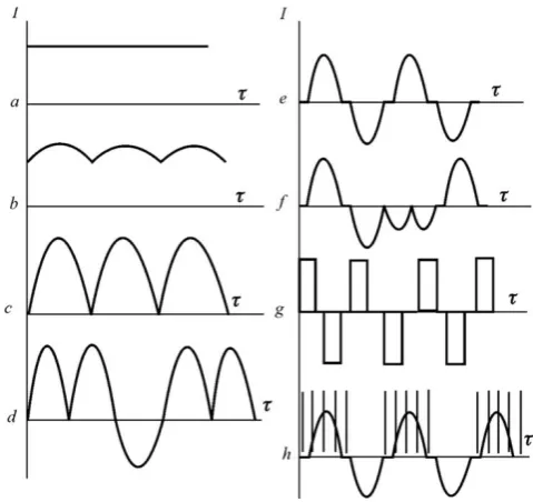
The possibilities of treatment by microarc method can be described by applied current modes, most preferable of which ones are represented on Figure 4. First three (a,b,c) modes are characteristic for anodic MAO with different ripple factor (from 3 up to 100 %) [4,6]. A mode d - anodic pulsating with submission through each 5-50 positive impulses one negative [5]. Anodic-cathode modes (e,f), including usual anodic-cathode MAO (ACMAO) and ACMAO with cathodizing (C), realized on the power supply with an industrial frequency f =50 Hz [3,12,13]. The last group of modes (g,h) – different impulse submissions of a current with frequency exceeding industrial, as a rule, up to 1 - 2 кHz. As a whole, the method of microarc oxidation is a complex process which characteristics are depended both from external factors (component composition, concentration, рН and temperature of electrolyte; mode of MAO: polarity, frequency, amplitude and form of voltage and current impulses, their ratio; treatment time etc.), and from internal factors (composition of alloy, its heat treatment, structure, porosity of oxidizing material etc.). These factors define the thickness of coatings, their composition, structure, density and porosity, microhardness, bond strength with a basis, wear- and corrosion resistance, electro- and thermal conduction, breakdown voltage and other properties [52,60].
Figure 4: Characteristic curves for currents modes of aluminum alloys at the microarc treatment: a – direct current; b,c – pulse current with different ripple factor; d –
anode pulsating with reverse impulses; e – anodic and cathode current of industrial frequency; f – combined anodic
and cathode current with cathodizing; g – anodic and cathode pulses; h – anodic and cathode current with
submission of high frequency pulses.
VI.
WEAR RESISTANCE OF MAO-COATINGS
IN DIFFERENT CONDITIONS
Because MAO-coatings have rather high mechanical characteristics (microhardness, elastic modulus etc.), for fast receiving of an estimation of their wear resistance the method of tests on abrasive outwearing is most acceptable [61].
of mass (on analytical balance W21 with exactitude ±0.0001 g) and linear by means of indicator 1ИГМ with an exactitude ±0.001 mm. The applying of two methods wear estimation has allowed us to control gross errors in measurements and to increase a level of reliability of the obtained data.
A plenty of materials and coatings that are applied for increase wear resistant of friction knots and links is known now. Among them it is possible to mark the composites on basis of tungsten carbides with copper-nickel bunch, different surface hardening materials, such as ПГ-ХН80Ср4, ВСНГН etc., siliconized graphite of the marks СГ-П, СГ-М, СГ-Т, mineral ceramic ЦМ-332 on a basis of Al2O3,
cemented-carbide compositions like ВК-6, ВК-8, Т15К6 [63,64] and others. The wear resistance of MAO-coatings was evaluated compared to following materials: composite on the basis of tungsten carbides WC-Cu-Ni, siliconized graphite СГ-П, and also cast iron СЧ18, steel 45, hardened up to HRC44 and steel 3 as the etalon.
The results of these tests are shown on Figure 5.
Figure 5: Comparable wear resistance of tested materials and coatings
One can see a very high wear resistance of MAO-coatings which one is comparable to wear resistance of materials traditionally used against an abrasive wear – composites on the basis of tungsten carbides. Moreover, characteristically that the linear wear grows proportionally with increase of specific load on contact down to Psp=1.5 MPa, while for cast iron, steel 3 and steel 45, at loading already over 1.00 MPa more wear watched.
Great interest represents also comparison of tests outcomes wear resistant of MAO-coatings with data of relative wear resistance investigations of materials carried out by other investigators [64,65]. Such comparison allows obviously present a level of a relative wear resistance of ceramic coatings as contrasted to wide range of materials. For realization of this, the data points of MAO-coatings relative wear resistance were entered onto a graph of relative wear resistance e from the ratio of hardnesses of abrasive particles and tested materials Ha/Hm (see Figure 6). Besides, for expansion of comparison spectrum on the same graph were put the data of relative wear resistance for different hardening coatings, surface hardening welding and modified layers received by modern methods of materials processing such as PVD-technologies [58], laser hardening [59] etc. reduced to the wear of the chosen etalon – steel 3. Out of Fig.6 one can see that the MAO-coatings have a very high wear resistance comparable to wear resistance of materials and coatings traditionally used against an abrasive wear: WC-Cu-Ni, boron layers (FeB, Fe2B),
ionic-vacuum coatings.
Figure 6: Dependence of relative wear resistance e of different materials, hardening layers and coatings from
hardness ratio of abrasive and materials Ha/Hm.
The reason of so high wear resistance of MAO-coatings, apparently, we should bind faster with their structural features than with their toughness characteristics (microhardness), because the structural modifications of alumina in MAO-coatings (α-, γ-, δ-Al2O3) during treatment form among themselves the
In [65] is specified that considerable increase of materials wear resistance is reached by introduction of high-tensile inserts. The big difference in properties α- and γ-Al2O3 allows considering the phase α-Al2O3 as
these high-tensile inserts in MAO-coating, due to which ones their high wear resistance is ensured. Thus, the complex of component MAO-coating phases of alumina represents some disperse system composed of a disperse phase (α-Al2O3), in a certain way distributed
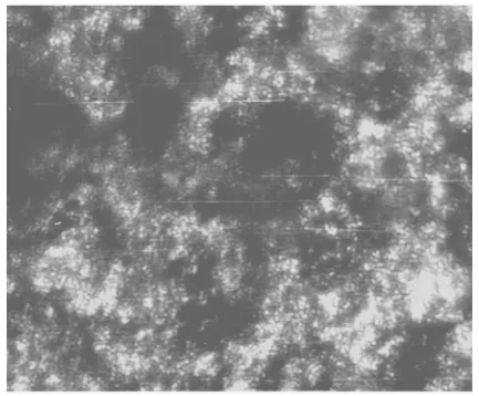
in dispersion (matrix) medium, or, the matter of fact – the composite material [66]. The legitimacy of such consideration of MAO-coatings is obvious. On metallographic section (Figure 7) the heterogeneity of structure and the presence of phase inserts as threadlike skeins of α-Al2O3 are visible.
Deeper microstructure investigations of different phases of alumina forming at MAO-treatment have shown [67] that is it a fact. In conditions of microarc discharges burning at the expense of high-speed crystallization, change of thermal fields and influence of internal stresses, there is a growth of crystals of phase formations in different structural states.
Figure 7: Microstructure of MAO-coating sample. One can see crystals threadlike of phase α -Al2O3twisted in skeins.
So, the basic hardening phase – α-Al2O3 can be in a
hardening layer in three kinds: bundles of separate single crystals, skeins of threadlike single crystals and cryptocrystalline form. It explains observable essential differences in toughness characteristics of MAO-coatings on different aluminum alloys having practically identical phase structure. The greatest wear resistance and toughness have the coatings in which ones α-Al2O3 consists from skeins of single threadlike
crystals built-in in cryptocrystalline matrix from γ-Al2O3 and mullite (3Al2O32SiO2). Such microstructure
has MAO-coating on duralumin (2024). The threadlike crystals of corundum twisted in skeins (Fig.7) together with a cryptocrystalline matrix from γ-Al2O3,
practically are deprived possibilities of deformation shifts at the expense of strain of one matrix.
VII.
IMPROVEMENT OF MAO-COATINGS
TRIBOTECHNICAL CHARACTERISTICS BY
MEANS OF
ULTRA-HIGH-MOLECULAR-WEIGHT-POLYETHYLENE (UHMWPE)
SURFACE MODIFICATION
There are many friction knots for which a low friction coefficient is very important, because they need to work under low level of lubrication or without it at all. These conditions are characteristic, for example, for the pair "ball - seating" of shut-off valves (ball valves), and others.
Tribological characteristics of working surfaces, strengthened by MAO, can be significantly improved by subsequent impregnation of coating porous system by the UHMWPE, which melts and fills in the porous structure of the coating and improves thus the contact geometry.
Presently, both Russian [42,37-39,68] and foreign scientists [69-73] pay a lot of attention to the study of MAO-coatings porosity. The fact is that the value of porosity significantly affects the physical, mechanical and tribological properties of coating. At high quantity of pores the basic physical and mechanical properties of the coating (HV, E and others) are reduced. The porosity affects the permissible value of the specific load too.
In such a way, the improvement of tribological properties of MAO coatings is becoming actual goal of achieving the minimum porosity of coatings, in particular, by choosing the optimal modes of formation process, as well as by use of special additional treatment.
The problem solution in this area can be achieved by applying the special treatment, which consists in impregnation of surface layer by various components, or applying an extra layer of protective material.
labor-intensive operations, surface preparation for coating: sandblasting and other methods of mechanical surface cleaning to ensure adhesion of the polymer to MAO-coating. The abrasive blast cleaning of samples surface in this case is not needed, because after microarc oxidation the samples have quite rough and porous surface, which provides a high adhesion of the polymer to the MAO-coating. The trials results (see
Figures 8, 9) suggest that the use of additional treatment (impregnation by UHMWPE) improves its antifriction properties [74].
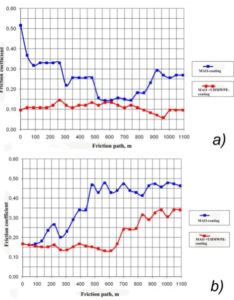
Figure 8: Dependences of friction coefficient changes for samples with MAO-coating and MAO+UHMWPE-coating during the experiment at the specific load of 2.0 MPa (a) and 5.0 MPa (b).
In addition, the tribological behavior of these composite coatings (MAO + UHMWPE) with comparison to MAO-coatings in various lubricant environments and specific loads up to 20.0 MPa were studied and evaluated in further experiments.
Figure 9: Dependence of friction coefficient from the specific load for the samples with MAO-coating and MAO
+ UHMWPE-coating.
Figure 10 shows the micrograph of the sample of MAO+UHMWPE-coating in cross-section.
Figure 10: Micrograph of threadbare sample with MAO+UHMWPE – coating in cross-section after test.
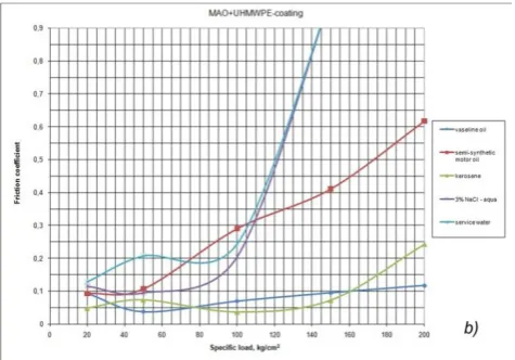
Figure 11: Dependence of friction coefficient from the specific load for the samples of MAO-coating (a) and
MAO+UHMWPE-coating (b) in various lubricant environments (see legend)
As can see from data of Figure 8, the reduction of friction coefficient (ffr) under specific load of 2.0 MPa
is almost 70%, and about 45% at the load 5.0 MPa. At the specific load of 10.0MPa the samples, made by recommended technology, showed good results and relatively low rate of wear of the samples and counter-body, as opposed to samples without polymer layer.
The roller sample as an element of friction pair wore during the tests also. But its wear value was more than the wear of the block sample, in spite of that its friction path was 10 times less.
Friction properties of new combination coatings with conventional MAO coatings were also evaluated in the same lubricants for comparison. It should be noted that impregnation of MAO-coating with UHMWPE significantly expands the applicability of new coatings at increased specific load (see Figure 11(a) and (b)). In this case, even in the environments that have poor lubricating properties, such as service water and 3% NaCl solution, the range of applicable specific load is increased to 10.0MPa compared with conventional MAO coating (6.0–7.0 MPa). In environments with good lubricating properties – kerosene, Vaseline oil, and semi-synthetic motor oil, the applicable range of specific loads is more expanded.
Therefore, such friction pairs can operate at the specific load up to 20.0MPa with a relatively low friction coefficient. Kerosene has a relatively good lubricating ability, but when it was tested in a friction pair of MAO-coating (block) - steel (roller) the value of friction coefficient has significantly narrower range
of the specific load (from 0 to 10 MPa), than the tested pair MAO+UHMWPE-coating and steel (from 0 to 20 MPa). This is due to the fact that kerosene was absorbed in the pores of the MAO coating at the high specific loads under the influence of friction heat evaporating from the surface, thereby worsening the lubricity of the surface friction. While for a friction pair of MAO+UHMWPE coating and steel, even at the specific load of 20.0 MPa, due to the added lubrication of polymer (UHMWPE), lubricating ability of friction surface is not impaired, as can be seen in Figure 11(b).
The best trial results (friction coefficient) were obtained for Vaseline oil, ffr=0.04 at the specific load
12.0 MPa. The good antifriction properties of composite material MAO+UHMWPE-coating are due to the fact that the MAO-coating as a hard base or frame, takes the main load from the friction pair action, and the polymer UHMWPE with its remarkable properties, even at the significant specific loads provide high lubricity ability of composite friction surface. The experimental data obtained allow us to improve working surfaces of friction details for some kinds of oil and gas equipments (e.g. in production of wear resistant balls and seals for ball valves and O-rings for piston pumps) and more other applications.
VIII.
MICROARC SURFACE MODIFICATION
TECHNOLOGY BY COATINGS FORMATION
IN SLURRY ELECTROLYTES
electrolyte as particles of disperse phase (DP). Different nonmetallic combinations: oxides, carbides, borides, nitrides of metals are used as particles of disperse phase. The sizes of entered particles vary in rather broad limits: from nanometers (ultra dispersed components) to 0.1–100 mm. The concentration of particles in electrolyte can be from 5 to 100 g/l.
The main investigations of MAO-coatings formation in slurry electrolytes are directed on selection of strengthening disperse phase and base electrolyte for deriving a matrix, definition of dependence of coatings composition and characteristics of disperse phase from parameters of electrolysis and elaboration of methods of coatings quality improvement.
The slurry electrolytes were prepared by dissolution of necessary amount alkali (potassium hydroxide) in distilled water and introduction in these ones the calculated amounts of dissoluble salts and disperse phase (oxides, carbides, nitrides, borides of metals) which previously were mixed by wet method (in a ball mill) with the calculated amount of ultra dispersed powder (for example, aerosil-amino).
The inclusion of disperse phase in MAO-coating is a result of complex interplay of particles with hydrodynamic, electrical, electro kinetic, concentration and other fields between an electrolyte and surface of forming coating. The electrophoresis [55] in the pure kind, as a rule, does not take place in anodic–cathode microarc treatment mode because of alternating electrode polarization and influence of other numerous factors also. But the particles of disperse phase which found themselves in a zone of microarc discharge are being involved in a volume treated by microarc and can be built-in by one or another way in a structure of formed coating. The properties of such composite material essentially will depend on a kind of status of powder material entered into electrolyte which could be found in a coating: either in an unchanged status or in combinations with other elements, or built-in in a crystal lattice of oxide. First of all it will depend on a type of combinations and their kind of bond between elements. Unlike typical standard electrolyte, the MAO-coating formation process in such slurry electrolytes has some diverse mechanism. The main difference of this mechanism is the following: due to the presence of weighed particles in an electrolyte, all processes of surface film formation intensify sharply. But, although the classic electrophoresis in
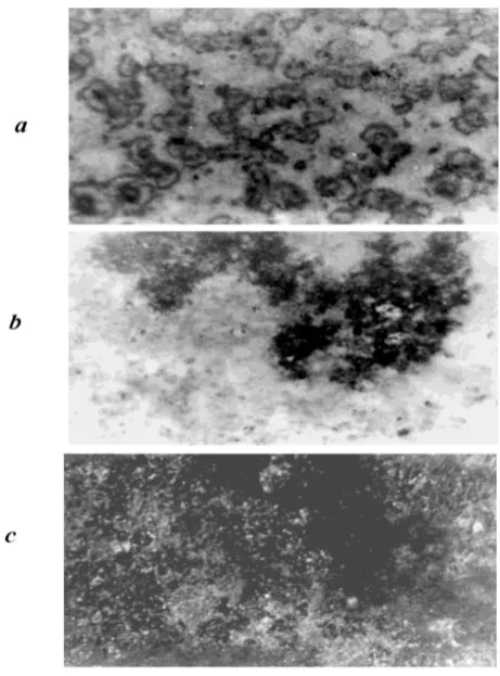
investigated slurry electrolytes is not exhibited distinctly, as was already remarked above, the presence of solid particles in electrolyte provides updating of formed coating in such a manner that powder materials entered into electrolyte are detected in a composition of ceramic film surface, not only visually (Figure 12), but by X-ray diffraction method also (Figure 13).
Figure 12: Microsections of MAO-coatings samples formed in slurry electrolytes with entered powders (x80): (a) AS
(alumosilicate); (b) oxide TiO2; (c) oxide Cr2O3
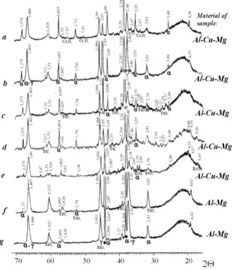
XRD patterns of coatings samples formed in different conditions are shown in Fig. 13, out of which follows that the oxides modifications γ- and α-alumina are the main components of coatings. Besides, depending on the type of used powder in slurry electrolyte (carbides, oxides, nitrides, etc.) the phase peaks of compounds— the oxides of zirconium, titanium, silicon, chromium (ZrO2, TiO2, SiO2, Cr2O3) can be found on the
coating and render an essential role in forming their properties.
For example, the particles of Al2O3 and TiC having
high mechanical characteristics give the heightened mechanical properties to formed coating and increase their wear resistance in particular.
Figure 13: XRD patterns of MAO-coatings samples formed in slurry electrolytes of following compositions (KOH + Na6P6O18)+: (a) Cr2O3; (b) BN; (c) TiO2 + NaAlO2; (d) TiC
+ NaAlO2; (e) ZrO2 + Na2SiO3; (f) TiO2; (g) AS
(alumosilicate). The labels of identified phases given in this figure: (α) α-Al2O3; (γ) γ-Al2O3; (•) Al3Mg2.
Some results on microhardness study and tests on abrasive wear resistance of MAO-coatings formed in slurry electrolytes are shown on Figure 14.
Analyzing the obtained data it is possible to mark that the coatings formed in slurry electrolytes have a wear resistance almost the same as coatings formed in ‗‗pure‘‘ standard electrolytes, like KOH + Na2SiO3 or
KOH + NaAlO2.
Figure 14: Comparative data on microhardness and intensity of abrasive wear of MAO-coatings formed in slurry electrolytes with added powders of oxides, carbides,
borides and nitrides of metals.
But the formation process decreases significantly the duration of treatment in 2–3 times, for coating thickness 200 μm, for example. So, the duration of coating formation with thickness more than 150 μm in some conditions lasts 30–40 min, while for usual electrolytes this process continues 120–150 min.
The powders entered into electrolyte are presented (see Fig. 13) in coatings in unchanged status in almost all cases. So, oxides TiO2, Cr2O3, ZrO2 and titanium
carbide TiC enter in composition of coating practically without changes, the ultra dispersed powder of alumosilicate (AS) is detected as SiO2, but the boron
nitride BN is not detected at all. Hence, depending on the compounds entering into electrolyte (oxide, carbide, boride or nitride of metal), their kind of bond and also their physical and chemical properties, the powder materials can be in the composition of coating after MAO-treatment both in unchanged or/and in changed status. This influences essentially on the properties of formed coating.
The held investigations of slurry electrolytes have allowed us to develop a new composition of electrolyte improving the quality of formed coatings by means of introduction into it the component stabilizing an electrolyte and containing a super fine powder of disperse phase. A new electrolyte [76] contains an alkaline compound and a disperse phase as oxides, carbides, borides and nitrides of metals into which one a chemically modified ultra dispersed earth silicon— aerosil-amino is added.
Aerosil-amino (Si–O–(CH2)2NH2) is a product of
chemically modified earth silicon (aerosil–SiO2) by
amino alcohols [77]. The amino-group –CH2CH2NH2
is engrafted on the surface of aerosil by means of substitution of silicon atom. These amino-groups allow stabilizing the slurry electrolyte because they provide the aerosil with hydrophobic properties (i.e. it wets bad by water). The ultra dispersed particles of modified aerosil have a size (ca. 0.1– 10 nm) considerably smaller than particles of disperse phase of slurry electrolyte and are adsorbed onto their surfaces. Because the only one part of aerosil-amino‘s surface is hydrophobic, but its another part is hydrophilic (i.e. provide the interplay with dispersion medium) the slurry electrolyte acquires a good stabilizing properties. The disperse phase contains powders of oxides, carbides, borides, nitrides of metals or their mixture with particles sizes from 5 to 100 μm. The shallow fraction is more preferable. The concentration borders of powder containing in an electrolyte are stipulated by profile of treated detail significantly. The more complicated configuration of detail demands a shallower fraction of powders. For simple working pieces it is more favorable to increase both the size of particles and their concentration. The stabilization of slurry electrolyte can be infringed at concentration of powder over than 100 g/l and at concentration less than 20 g/l the effectiveness of used powder is not so obvious. The exit out of mentioned above concentration borders influence the coatings quality. The particles of oxides, carbides, borides and nitrides of metals together with adsorbed onto their surfaces the particles of aerosil-amino participate in transition of mass from electrolyte to the working electrode, their precipitation and incorporation in a lattice of alumina during microarc oxidation process. The obtained by such method composite material of coating has a heightened toughness through the modification by particles of disperse phase with high elastic modulus and providing their best interplay with matrix material
(α- and γ-alumina) on the boundary between reinforced particles and matrix.
The results of investigations of different variants of slurry electrolytes demonstrate that the proposed electrolyte allows obtaining a coating with high strength properties.
IX.
CONCLUSION
The basic difference of microarc oxidation process from traditional anodizing is use of electric discharges energy migrating on the treated details surface immersed into electrolyte. These discharges render particular thermal, plasma chemical and hydrodynamic influences on the basic metal, coating and electrolyte. Thus, the ceramic coatings can be formed with adjustable in wide ranges of elements and phases compositions, structures, and properties.
For characteristic features of MAO-process it is possible to indicate also high temperatures in discharge channels and, as consequent, the formation of high-temperature phases in coatings (for aluminum alloys it is a hard corundum - α-Al2O3); the destruction of
water with formation of atomic and ionized Oxygen; local magnification of electrolyte concentration and particular plasma chemical reactions in a zone of discharge; local sequential transformation in discharge of oxides formed by electrochemical way.
The structure and composition of oxide layers, apart from the nature of treated metal and other little significant internal factors, is defined by the environmental conditions of their formation and especially by composition of electrolyte components which can enter into coating structure, by time and technological parameters of processing mode defining thermal, temporary, and other characteristics of microdischarges.
The introduction into electrolyte a powders of disperse phase, besides improving coatings properties, allows to intensify all stages of coatings formation process considerably, diminishing duration of exposition in 2– 3 times. The addition into slurry electrolyte the ultra dispersed powder such as aerosil-amino allows to improve not only stabilizing properties of electrolyte, but to increase strength properties of MAO-coatings considerably.
The multifunctionality of MAO-coatings promotes their application in different industries. The spectrum of working details constantly is enlarged. Nevertheless, the possibilities of MAO-method are being not investigated still completely. The works on perfecting the process are continued: by improvement of new electrolytes, by selection of optimal modes, by development and creating of new technological current sources.
X.
REFERENCES
[1] Microarc oxidation. Science and humanity. Znanie: Moscow, 1981, p. 341 in Russian].
[2] Markov G.A., Shulepko E.K., Terleeva O.P. Method of coatings deposition on metals and alloys. Publish. Bull. Inv. 13, 1989. Copyright Certificate 1200591 C 25D 11/02 in Russian]. [3] Markov G.A., Gizatullin B.S., Rychazhkova I.B.
Method of electrolytic deposition of silicate coatings. Publish. Bull. Inv. 17, 1982. Copyright Certificate 926083 C 25 D 11/02 in Russian]. [4] Markov G.A., Shulepko E.K., Zhukov M.F.,
Petshevitsky B.I. Method of metalsand alloys oxidation. Publish. Bull. Inv. 17, 1982. Copyright Certificate 926084 C 25 D 11/02 in Russian]. [5] Markov G.A., Belevantsev V.I., Terleeva O.P., et
all. Microarc oxidation. Vestn. MSTU, Ser.Machinostr. 1, 1992, 34-56 (ISSN 0236-3941) in Russian].
[6] Markov G.A., Terleeva O.P., Shulepko E.K. Microarc and arc methods for deposition of protecting coatings. I.M.Gubkin MINKH and GP, Collection of Works, Moscow, vol.185, 1985, 54-66 in Russian].
[7] Sluginov N.P. J. Phys. and Chem. Soc., 1880, Vol.12, Iss.1,2 Physical part, p.1933.
[8] Guenterschulze A., Betz H. Neue Untersuchungen ueber die elektrolitische Ventilwirkung. V. Die Eigenschaften der Funken. Z. Physik.1932, V.78, 196-210.
[9] Mc Neil W, Wick R. Effect of various polyvalent metal anion addition to an alkaline magnesium anodizing bath. J. Electrochem Soc. 1957, V. 104, № 6, 356-359.
[10] Mc Neil W. The preparation of cadmium niobate by an anodic spark reaction J. Electrochem Soc. 1958, V. 105, № 9, 544-547.
[11] Gruss L.L., Mc Neil W. Anodic Spark Reaction Products in Aluminate, Tungstate and Silicate Solutions. J. Electrochem. Technol. 1963, V.1, № 9-10, 283-287.
[12] Mc Neil W., Gruss L.L. Anodic film growth by anion deposition in aluminate, tungstate and phosphate solutions. J. Electrochem. Soc. 1963, V. 110, № 8, 853-855.
[13] Mc Neil W., Gruss L.L., Husted D.G. The anodic synthesis of CdS films. J. Electrochem. Soc. 1965, V. 112, № 7, 713-715.
[14] US Patent № 2,753,952 (15.11.55.). H.A. Evangelides. HAE process.
[15] US Patent № 2,778,789 (22.01.57.). Mc Neil W. Cr-22 process.
[16] US Patent №3,293,158 (20.12.66.) Mc.Neil W., Gruss L.L. Anodic Spark Reaction Processes and Articles. C l. 204-56.
[17] Brown S.D., Kuna K.J., Tran Bao Van. Anodic Spark Deposition from Aqueous Solutions of NaAlO2 and Na2SiO3. J. Amer. Ceram. Soc. 1971. V. 54, № 4, 384-390.
[18] Tran Bao Van, Brown S.D., Wirtz G. P. Mechanism of Anodic Spark Deposition. Amer. Ceram. Bull. 1977. V. 56, № 6, 563-568.
[19] Markov G.A., Markova G.V. Method of electrolytic condensers anode forming. Publish. Bull. Inv. 32, 1976. Copyright Certificate 526961 H 01G 9/24 in Russian].
[20] Nikolaev A.V., Markov G.A., Petshevitsky B.I. New phenomenon in electrolysis. Izv. SB of RAS, Chemical science, 1977, Vol.5, №12, 32-33 in Russian].
[21] Karanik Yu.A., Markov G.A., Minin V.F., et all. Method of manufacture metallic casting form. Publish. Bull. Inv. 45, 1977. V.F. Copyright Certificate 582894 B 22 D 15/00 in Russian]. [22] Karanik Yu.A., Markov G.A., Minin V.F., et all.
Method of manufacturecastings mouldes and cores. Publish. Bull. Inv. 15, 1979. Copyright Certificate 657908 B 22 D 15/00, B 22C 9/00 in Russian]. [23] Markov G.A., Terleeva O.P., Shulepko E.K.
[24] Malyshev V.N., Markov G.A., Fedorov V.A., Petrosyants A.A., et all. Features of structure and properties of coatings formed by microarc oxidation method. Chemical and oil machine industry, 1984, №1, 26-27 in Russian].
[25] Markov G.A., Belevantsev V.I., Slonova A.I., Terleeva O.P. Stagety in anodic-cathode microplasma processing. Electrochemie. 1989, Vol. 25, № 11, 1473-1479 in Russian].
[26] Mironova M.K. About film formed by anode microarc oxidation. Protection of metals. 1990, Vol.26, №2, 320-323 in Russian].
[27] Snizhko L.A. Beskrovny Yu.M., Nevkryty V.I., Chernenko V.I. Impulse mode for deriving silicatecoatings in spark discharge. Protection of metals. 1980, Vol.16, №3, 365-367 in Russian]. [28] Snizhko L.A., Tikhay L.S., Udovenko Yu.Z.,
Chernenko V.I. Anode-spark deposition of silicates on alternative current. Protection of metals. 1991, Vol.27, №3, 425-430 in Russian].
[29] Chernenko V.I., Snizhko L.A., Papanova I.I. Deriving of coatings by anode-spark electrolysis. Khimiya: Leningrad. 1991, p.128 in Russian]. [30] Gordienko P.S., Yarovaya T.P. Definition of
microarc oxidation parameters onvoltage-current characteristics. Electronnaya obrabotka materialov. 1990, № 6, 44-48.in Russian].
[31] Gordienko P.S., Gnedenkov S.V., Sinebrukhov S.L., Zavidnaya A.G. About growth mechanism of MAO on titanium. Electronnaya obrabotka materialov. 1991, № 2, 42-46.in Russian].
[32] Gordienko P.S., Gnedenkov S.V. Microarc oxidation of titanium and its alloys. Dalnauka: Vladivostok, 1997. p.186 in Russian].
[33] Rudnev V.S., Gordienko P.S., Kurnosova A.G., Ovsyannikova A.A. Electrolyte influence on result of aluminum alloys microarc oxidation. Protection of metals. 1991, Vol.27, №1, 106-110 in Russian]. [34] Fedorov V.A., Velikoselskaya N.D. Phys. Chem.
Mater. Treat. 1990, №4, 57-62 in Russian].
[35] Fedorov V.A., Belozerov V.V., Velikoselskaya N.D. Phys. Chem. Mater. Treat. 1991, №1, 87-93 in Russian].
[36] Malyshev V.N. Investigation of coatings service properties formed by microarc oxidation method. Protective coatings on metals. 1989, Vol.23, 85-88 in Russian].
[37] Malyschev V.N. Neue
Anwendungsmoeglichkeiten fuer Aluminium. Metalloberflaeche, 2006, № 1-2, 28-29.
[38] Malyschev V.N. Mikrolichtbogen-Oxidation – ein neuartiges Verfahren zur Verfestigung von
Aluminiumoberflaechen. Metalloberflaeche, 1995, № 8, 606-608.
[39] Malyshev V.N. Features of coatings forming by anodic-cathode microarc method. Protection of metals. 1996, Vol.32, №6, 662-667 in Russian]. [40] Malyshev V.N. Selforganisated processing at the
coatings formation by microarc oxidation method. Advanced materials. 1998, №1, 16-21 in Russian]. [41] Malyshev V.N. Effective Electrochemical
Transformation Method of Valve Metals Surface Layer into High-tensile Ceramic Coating./Chapter 7 in Book: Chemical Reactions on Surfaces. Editor:J.I.Duncan and A.B.Klein, 2008 Nova Science Publishers, Inc.,pp. 211-262.
[42] Petrosyants A.A., Malyshev V.N., Fedorov V.A., Markov G.A. Trenie I Iznos, 5, 1984, 350-354 (for English translation see J. Friction and Wear, ISSN 1068-2666) in Russian].
[43] Jamada M., Mita J. Formation of Eta-Alumina by Anodic Oxidation of Aluminum. Chem. Lett. 1982, № 5, 759-762.
[44] Dittrich K.H., Krysmann W., Kurze P., Schneider H.G. Structure and Properties of ANOF layers. Crystal Res. And Technol. 1984. V.19. № 1, 93-99.
[45] Krysmann W., Kurze P., Dittrich K.-H., Schneider H.G. Process Characteristics and Parameters of Anodic Oxidation by Spark Discharge (ANOF). Crystal Res. and Technol. 1984. V19. № 7, 973-979.
[46] EP 0.280.886 A1.(01.02.88) C 25 D 11/02. Krysmann W., Kurze P., Berger M., Rabending K., Schreckenbach J., Schwarz T., Hartmann K.-M. Verfahren zur Herstellung dekorativer Ueberzuege auf Metallen.
[47] Kurze P., Schreckenbach J., Schwarz Th., Krysmann W. Beschichten durch anoducsche oxidation unter Funkenentladung (ANOF). Metalloberflaeche, 1986 B.40, № 12, 539-540. [48] Pat 3,812,021 USA. Inorganic Coatings for
Aluminous Meals/ H.L. Graig, H.J. Coates. -1974 (21.05) (C23B 9/02).
[49] Pat. 3,832,293 USA. Process for Forming a Coating Comprising a Silicate on Valve Group Metals /R.J. Hradcovsky, S.H. Bales. 1974 (27.08) (C23B 9/02, 11/02).
[50] Pat. 4,082,626 USA. Process for Forming a Silicate Coatings /R.J. Hradcovsky. 1978 (4.04) (C25D 11/02, 11/06, 11/34).
[52] Timoshenko A.V., Opara B.K. Kovalev A.F. Microarc oxidation of alloy D16 on alternative current in alkali electrolyte. Protection of metals. 1991, Vol.27, №3,.417-424 in Russian].
[53] Kuskov V.N., Kuskov Yu.N., Kovensky I.M., Matveev N.I. Features of coatings growth at the microarc oxidation of aluminum alloy. Phys. Chem. Mater. Treat. 1996, №6, 101-103 in Russian].
[54] Bakovets V.V., Polyakov O.V., Dolgovesova I.P. Plasma electrolytic anode treatment of metals. Nauka: Novosibirsk, 1991, p. 168. in Russian]. [55] Dukhin S.S., Deryagin B.V. Electrophoresis.
Nauka: Moscow. 1976, p.332 in Russian].
[56] Markov G.A., Shulepko E.K., Terleeva O.P. Unit for transformation alternating voltage in asymetric alternating. Publish. Bull. Inv. 35, 1987. Copyright Certificate 1339818 H 02M 5/257 in Russian]. [57] Markov G.A., Shulepko E.K., Terleeva O.P. Unit
for transformation alternating voltage in asymetric alternating. Publish. Bull. Inv. 26, 1989. Copyright Certificate 1451821 H 02M 5/257 in Russian]. [58] Semenov A.P., Kovsh I.B., Petrova I.M. et all.
Methods and means of details machines surfaces hardening by concentrated flows of energies. Nauka: Moscow, 1992, p. 404 in Russian].
[59] Stafford K.N. et all. Coatings and surface treatment for protection from corrosion and wear. Metallurgy: Moscow, 1991, p.238 in Russian]. [60] Aluminum alloys. Structure and properties of
half-finished products from aluminum alloys. Handbook. Metallurgy: Moscow, 1974. p. 432. in Russian].
[61] Khrutshev M.M., Babichev M.A. Abrasive outwearing. Nauka: Moscow, 1970, p.252 in Russian].
[62] Malyshev V.N., Golub M.V., Kharlamenko V.I. Investigation of composite materials relative wear resistance. VNIIOENG. Machines and oil equipment, 1983, № 4, 6-8 in Russian].
[63] Katsheev V.N. Processes in a zone of metals friction contact. Mashinostroenie: Moscow, 1978, p.213 in Russian].
[64] Vinorgadov Yu. M. Wear resistant materials in chemical machine industry. Handbook. Mashinostroenie: Leningrad, 1977, p. 256 in Russian].
[65] Khebda M., Chichinadze A.V., et all. Handbook on tribotechnic. Theoretical basis. Mashinostroenie: Moscow, 1989, Vol.1, p.400 in Russian].
[66] Fedorchenko I.M., Pugina L.I. Composite heated antifriction materials. Naukova dumka: Kiev, 1980, p.404 in Russian].
[67] Alekhin V.P., Fedorov V.A., Bulychev S.I., Tyurpenko O.A. Features of microstructure of hardened surgace layers obtained by microarc oxidation. Phys. Chem. Treat. Mater. 1991, № 5, 121-126 in Russian].
[68] Gnedenkov S.V., Khrisanphova O.A., Zavidnaya A.G., Sinebrukhov S.L., Kovryanov A.N., Scorobogatova T.M., Gordienko P.S. Production of hard and heat-resistant coatings on aluminium using plasma micro-discharge. Surf. Coat. Technol., 2000, № 1(123), Р. 24-28
[69] Yerokhin A.L., Nie X. and Leyland A. et al., Plasma electrolysis for surface engineering, Surf. Coat. Technol. 122 (1999) (2–3), pp. 73–93. [70] Yerokhin A.L., Snizhko L.O., Gurevina N.L.,
Leyland A., Pilkington A. and Matthews A. Discharge characterization in plasma electrolytic oxidation of aluminium, J.Phys.D: Appl.Phys. 36 (2003), pp. 2110-2120.
[71] Ding, H.-y., Dai, Z.-d., Skuiry, S.C., Hui, D. Corrosion wear behaviors of micro-arc oxidation coating of Al2O3 on 2024Al in different aqueous environments at fretting contact. Tribology International, 2010, 43 (5-6) , pp. 868-875.
[72] Sundararajan, G. and L.R. Krishna, Mechanisms Underlying the Formation of Thick Alumina Coatings through the MAO Coating Technology. Surf. Coat. Technol., 2003. 167: Р. 269-277. [73] J.A. Curran, T.W. Clyne, Porosity in plasma
electrolytic oxide coatings. Acta Materialia 54, 2006.
[74] Malyshev V.N., Volkhin A.M. Antifriction properties increasing of ceramic MAO-coatings. Proc. IMechE Part J:J Engineering Tribology, 2014, V.228(4), P.435-444.
[75] Malyshev V.N., ZorinK.M. Features of microarc oxidation coatings formation technology in slurry electrolytes. Applied Surface Science, 2007 (254), 1511-1516
[76] V.N. Malyshev, S.I. Bulychev, N.V. Malysheva, An electrolyte for microarc oxidation of aluminum and its alloys, Publish. Bul. Inv. 18, 1995. (Patent of Russian Federation No. 2038428 C 25 D 11/06) in Russian]